How to connect a three-phase motor via a magnetic starter
Power supply 380 V (three phases) is carried out in the same way, only there will be more power wires.
The contactor includes not one, but three phase lines. In this case, the control button is connected according to a similar circuit (as in the single-phase case).
The illustration shows a starter with a 380 V solenoid control coil. The control circuit is switched between any two phases. For safety, there is a thermal relay, the sensors of which can be located on one or several phase wires.
How to connect a 3-phase contactor with a 220 V starter winding? The circuit is similar, only the control circuit is switched between any of the phases and the neutral wire. The thermal relay works just as accurately, since its mechanism is tied to the temperature of the power cables.
Relay diagram on MK
First, about the hardware of the project. It is not much different from the previous version except for a few improvements such as opto-isolation between the I/O microcontroller and the relays in the control circuit.
Power supply: the entire circuit operates from a stabilized 5V power supply on the LM7805. To reduce the heat generation in the voltage regulator, the recommended DC input voltage is selected as 9V, which can be easily obtained from the AC adapter. The board has a 2-pin terminal block for the load and a standard 2.1 mm connector for receiving input voltage.
Relay installation, typical connection diagram
Relay installation work must be carried out by a suitably qualified specialist.
• Mount the relay on a standard DIN rail like a regular circuit breaker. If you plan to mount the relay directly to a surface without a DIN rail, use a screwdriver to carefully press out the latches on the bottom of the relay housing and move them to the next position. You can now secure the relay with self-tapping screws to a suitable dielectric surface. • Connect the power terminals of relay A1 and A2 to a 220V/50Hz power supply. The green “power” LED on the relay should light up. • Using a smartphone or laptop, find a wireless network (the name of the network is indicated in the passport). • Connect to the network using the password specified in your passport • Open your browser and enter the address https://iot-modul.ru
You should see the main time relay control window. You can configure the relay based on your tasks, and also do not forget to change the security settings: password and login for connection.
Main page for relay monitoring and control. The main page loads at https://iot-modul.ru when you are connected to the relay in access point mode via a WiFi network. To connect to the device in LAN mode, use the device’s IP address or SSDP name. The main time relay controls contain several panels. The appearance and content of control screens depends on the selected operating mode.
After you have completed all the settings, you can visually determine the operation of the relay contacts by the yellow LED on the front panel. The relay has one group of “switching” contacts. Contact “11” is a common contact, contact “12” is a normally closed contact, contact “14” is a normally open contact. As an example of electrical load control, we can offer the following connection diagram:
Purpose and types
A time relay provides the ability to set a specific time interval necessary for the operation of electrical equipment. It is often used in cases where various devices are expected to automatically turn on after a certain period of time.
In everyday life, time relays are used to save electricity. By automatically turning on and off household appliances and lighting, the population significantly saves their budget. In addition, this device is in demand among consumers due to its long service life, as well as practicality in use.
A cyclic type device triggers a signal after a set time period. The original version of this type was mechanical. It interacted with the contacts through a programmed motorized drum. When microprocessors appeared, relays began to have different range criteria. Cyclic relays are mostly used in street lighting.
The intermediate type provides a temporary delay when connecting an electrical appliance at a set moment. Such a delay is necessary for the correct and correct operation of electrical devices that have a complex mechanism. In turn, intermediate relays are divided into electromagnetic relays; pneumatic devices; devices with a clock mechanism; electronic relays; as well as motor relays.
Block relays are used in areas of narrow specialization, for example, time delay of photo printing. The block device has a built-in power supply and is installed as an independent device.
The embedded device does not have a housing or its own power source. A relay is part of a more complex mechanism. It is used as an auxiliary element, and has a common body with other elements. The most common example is an automatic washing machine.
Modular devices are similar to block varieties. Often they are installed in distribution panels on a DIN rail.
Electromagnetic
This type is used only in networks with direct current. The relay is equipped with a short-circuited winding similar to a copper sleeve. The time delay occurs due to this sleeve, which prevents the increase in magnetic flux and the activation of the main relay armature. The device can be installed for a time period of five seconds. These types are used in electric drives for the purpose of accelerating or braking them.
Electromagnetic relay
Electronic
Electromagnetic devices have a time delay programming function. Analog and digital types are available. The device controls processes in electronic circuits, counts a set number of pulses, and regulates the discharge and charge of capacitors. Such devices are widely used in everyday life.
Pneumatic
The relay is called pneumatic because it contains a pneumatic cataract in its mechanism. By means of a special adjusting screw, the diameter of the hole that absorbs air changes, resulting in a time delay. Such a device can be programmed for a sixty-second delay. This product can be used for automatic control of electrical equipment, as well as for controlling an electric drive, its acceleration and braking.
Motor
These types are used to protect overhead lines when they are reconnected. The main element of this device is a synchronous motor, which operates using an alternating current electrical network with a frequency of 50 Hertz. In addition, the relay mechanism includes an electromagnet, through which the motor and gearbox are coupled. The device is capable of producing a time delay from ten seconds to several hours.
With clock mechanism
This relay is based on a spring. The electromagnet included in the design drives this spring into action. The required time is set on a special scale, after which the relay contacts close. The time period can be set from 0.1 to 20 seconds.
Time relay with clock mechanism
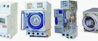
Weekly timer
An electronic on-off timer in automatic mode is used in various fields. The “weekly” relay switches within a predetermined weekly cycle. The device allows:
- Provide switching functions in lighting systems.
- Turn on/off technological equipment.
- Start/disable security systems.
The dimensions of the device are small; the design includes function keys. Using them, you can easily program the device. In addition, there is a liquid crystal display that displays information.
Control mode can be activated by pressing and holding the “P” button. The settings are reset using the “Reset” button. During programming, you can set the date, the limit is a week. The time relay can operate in manual or automatic mode. Modern industrial automation, as well as various household modules, are most often equipped with devices that can be adjusted using potentiometers.
The front of the panel assumes the presence of one or more potentiometer rods. They can be adjusted using a screwdriver blade and set to the desired position. There is a marked scale around the stem. Such devices are widely used in control structures of ventilation and heating systems.
Operating principle
The relay is triggered by a physical or mechanical influence: the appearance of a control electric current, an increase or decrease in local illumination, the formation or change of a local magnetic field, thermal energy, sound pressure, etc.
Time relays are also used: they operate after a specified time interval or at a designated moment (if the control signal has not appeared earlier). Such models are installed to turn on or start certain mechanisms or processes, turn them off or regulate them.
In everyday life, such devices are used almost everywhere: a timer for a washing machine or heating system, a microwave oven or electric oven, a street traffic light or lighting. Such relays are already built into the design of the product and are most often designed for repair or replacement. Due to the complexity and uniqueness of most timer designs, it is recommended to contact service repair shops.
However, you can replace, repair and install it back, or simply install a new timer yourself. They are installed in a limited range of devices (heating, ventilation and heating devices, as well as some individual mechanisms), so their principle of operation is known and can be regulated.
Configuring electronic-mechanical analog relays
Industrial automation systems, as well as various household modules, are often equipped with electromechanical devices, the design of which allows for adjustment using potentiometers.
Electromechanical type of time counting device with parameter adjustment by potentiometers. There are various configurations of such devices, which makes it possible to use them in circuits of varying complexity.
On the front panel of the housing of such devices there is a potentiometer rod (or several rods) designed for rotation with a screwdriver blade. A marked scale of installation values is applied around the circumference of the rod(s).
The slot on the rod for the screwdriver blade is a kind of pointer that changes its position when the rod rotates. By placing this pointer opposite certain values of the marked scale, the desired parameter can be adjusted.
Multichannel device of electronic-mechanical type. Adjustment is easy and simple by rotating the potentiometers with a screwdriver. The front panel also has LED status indication
Devices of this type (for example, NTE8) are widely used in control circuits for ventilation systems, heating modules, and artificial lighting devices.
Relay testing
Relay testing
Electronic devices operate on the basis of digital impulses. Modern devices have high-performance microprocessors. Typically, the RF is designed for switching inductive or non-inductive loads. To configure a digital type device, you will need to enter the required time parameters using the function keys. The possibility of wide customization allows you to set not only seconds, but also days of the week.
The purpose of testing is to understand the design and operating principle of a time relay. The device is checked when switched on again in the following sequence.
- External inspection and mechanical inspection.
- Checking the operation of the spark arresting circuit.
- Testing the rectifier device.
- Determination of the current resistance of the winding circuit.
- Checking the voltage during operation and return.
- Response time control.
Testing of the main parameters is carried out using a special device. When inspecting the mechanical part, corrosion and contamination are revealed. Check the movement and balancing of moving parts, the condition of axes and springs, the tightening of screws and axial play.
An important point is to check the insulation strength. Voltage is applied alternately to all bases and clamps. The insulation must withstand a voltage of 1000 V at an alternating current frequency of 50 hertz.
How to connect a relay
If frequency converters are used when connecting industrial or household equipment, then the use of a phase control relay is not at all necessary.
Direct connection is carried out according to the instructions on how to connect a relay of this particular type. Quite often the connection diagram is shown on the device body
To do this, you should pay attention to various photos of phase control relays.
Connection to external and internal sources is carried out using wires with clamps. Either one wire with a cross-section of 2.5 mm or two wires with a cross-section of up to 1.5 mm are supplied under it. To connect, it is necessary to observe strict alternation of phases A, B and C.
Usually the relay checks the plus break, their alternation, and the network voltage level. When a fault is detected in the network, the relay comes into action. The connection diagram can be either three-wire without zero, or four-wire with zero. In apartments, this connection scheme is often used. The connected load is formed evenly on each of the 3 phases.
When any of the phases goes beyond the specified values, the relay responsible for this circuit is activated, and the rest of the load (provided it is within the required range) continues to operate.
Let's consider a connection diagram with zero. This circuit provides complete control over the voltage on each phase, skew and correct alternation, and it is also worth noting the fact that they are used as an industrial option. At the output of the device, using a power contact, we connect a contactor, which with one end of its winding is connected to the neutral wire, and the other end to the output of one of the phases.
Contacts 1, 2 and 3 connect the voltage removed from the voltage control relay to any three-phase load such as an electric motor, or high-power flow heaters, etc. The internal circuit of the relay measures the voltage value on each of the phases and when U is within normal values, it supplies energy to the connected contactor. This, in turn, keeps the contacts in a closed state, and the voltage reaches the external connected load.
If the voltage on any of the phases goes beyond the range we set, the relay stops powering the winding of our contactor and it, in turn, opens its contacts, de-energizing the entire connected external load.
Installation errors
The main mistake is connecting a time relay to devices with too much load, for example, an electric boiler. To control the heater, it is necessary to connect a relay through a magnetic starter connected to the boiler.
Also, no less often, time relays are installed in rooms with climatic conditions that are not suitable for normal operation of the device. The temperature should be in the range of -20 - 50°C with a humidity not exceeding 80%.
- Installing a magnetic starter (diagram)
- What is a power limiter (application)
- UZM-3-63 protection device and connection diagram
- How to choose a circuit breaker by power, current, pole
- Installing a power limiter (diagram)
Why is a time relay needed?
The purpose of a time relay varies depending on its functionality and technical features. Thus, an electromagnetic relay, which allows a one-second delay in switching on, is used in electrical control panels for starting high-power electric motors.
Housewives use a completely different type of relay to turn off household electrical appliances at the required time interval.
You can control the lighting on/off throughout the whole week by programming an electronic timer. A number of devices used in working with street lighting, through the execution of a program, are able to monitor fluctuations in the level of natural light throughout the day.
A cyclic time relay makes it possible to ventilate the interior space at set time intervals. And by adding sensors to the system that measure temperature and humidity, you can organize comfortable maintenance of objects such as a greenhouse or greenhouse.
Power relays - contactors
Since most of the relays discussed above are designed to switch loads with a power from hundreds of watts to ten kilowatts, additional high-power switching relays - contactors - are used to increase the switching power. With their help, you can switch a load of several hundred kilowatts, thereby expanding the capabilities of the previously discussed relays.
The use of various types of relays allows you to optimize the operation of many electrical appliances, protect against their accidental failure, and save your own life. On their basis, it is possible to create a large number of small automation systems, such as devices for maintaining an optimal microclimate, irrigation systems, automatic door opening, light switching on and off, and many others. Compact dimensions and standard dimensions of the case allow you to connect them directly to standard sockets or use ready-made electrical boxes for their installation, which significantly reduces the cost of automation in general.
Connection diagrams for a magnetic starter with a 220 V coil
Before we move on to the diagrams, let’s figure out what and how these devices can be connected. Most often, two buttons are required - “start” and “stop”. They can be made in separate housings, or they can be a single housing. This is the so-called push-button post.
Buttons can be in the same housing or in different ones
Everything is clear with individual buttons - they have two contacts. One receives power, the other leaves it. There are two groups of contacts in the post - two for each button: two for start, two for stop, each group on its own side. There is also usually a ground terminal. Nothing complicated either.
Connecting a starter with a 220 V coil to the network
Actually, there are many options for connecting contactors; we will describe a few. The diagram for connecting a magnetic starter to a single-phase network is simpler, so let's start with it - it will be easier to understand further.
Power, in this case 220 V, is supplied to the coil terminals, which are designated A1 and A2. Both of these contacts are located at the top of the case (see photo).
This is where you can supply power to the coil.
If you connect a cord with a plug to these contacts (as in the photo), the device will be in operation after the plug is inserted into the socket. In this case, any voltage can be applied to the power contacts L1, L2, L3, and it can be removed when the starter is triggered from contacts T1, T2 and T3, respectively. For example, a constant voltage from a battery can be supplied to the inputs L1 and L2, which will power some device that will need to be connected to the outputs T1 and T2.
Connecting a contactor with a 220 V coil
When connecting single-phase power to the coil, it does not matter which output is supplied with zero and which with phase. You can switch the wires
Even most often, the phase is supplied to A2, since for convenience this contact is located on the bottom side of the case
And in some cases it is more convenient to use it and connect the “zero” to A1
Even most often, the phase is supplied to A2, since for convenience this contact is located on the bottom side of the housing. And in some cases it is more convenient to use it and connect the “zero” to A1.
But, as you understand, this scheme for connecting a magnetic starter is not particularly convenient - you can also supply conductors directly from the power source by building in a regular switch. But there are much more interesting options. For example, you can supply power to the coil through a time relay or a light sensor, and connect the street lighting power line to the contacts. In this case, the phase is connected to contact L1, and zero can be taken by connecting to the corresponding coil output connector (in the photo above it is A2).
Diagram with start and stop buttons
Magnetic starters are most often installed to turn on an electric motor. It is more convenient to work in this mode if there are “start” and “stop” buttons. They are connected in series to the phase supply circuit to the output of the magnetic coil. In this case, the diagram looks like the figure below
note that
Switching diagram of a magnetic starter with buttons
But with this method of switching on, the starter will operate only as long as the “start” button is held down, and this is not what is required for long-term operation of the engine. Therefore, a so-called self-catching circuit is added to the circuit. It is implemented using auxiliary contacts on the starter NO 13 and NO 14, which are connected in parallel with the start button.
Connection diagram for a magnetic starter with a 220 V coil and a self-retaining circuit
In this case, after the START button returns to its original state, power continues to flow through these closed contacts, since the magnet has already been attracted. And power is supplied until the circuit is broken by pressing the “stop” key or by triggering a thermal relay, if there is one in the circuit.
Power for the motor or any other load (phase from 220 V) is supplied to any of the contacts marked with the letter L, and is removed from the contact marked T located underneath it.
It is shown in detail in what order it is better to connect the wires in the following video. The whole difference is that not two separate buttons are used, but a push-button post or push-button station. Instead of a voltmeter, you can connect a motor, pump, lighting, or any device that operates on a 220 V network.
Current relay device
First, let's look at the principle of a current relay and its design. At the moment, there are electromagnetic, inductive and electronic relays.
We will disassemble the structure of the most common electromagnetic relays. Moreover, they provide the opportunity to most clearly understand their operating principle.
- Let's start with the basic elements of any current relay. It must have a magnetic circuit. Moreover, this magnetic circuit has a section with an air gap. There may be 1, 2 or more such gaps, depending on the design of the magnetic core. In our photo there are two such gaps.
- There is a coil on the stationary part of the magnetic circuit. And the moving part of the magnetic circuit is secured by a spring, which counteracts the connection of the two parts of the magnetic circuit.
- When voltage appears on the coil, an emf is induced in the magnetic circuit. Thanks to this, the moving and stationary parts of the magnetic circuit become like two magnets that want to connect. A spring prevents them from doing this.
- As the current in the coil increases, the emf will increase. Accordingly, the attraction between the moving and stationary sections of the magnetic circuit will increase. When a certain current value is reached, the EMF will be so great that it will overcome the resistance of the spring.
- The air gap between the two sections of the magnetic circuit will begin to decrease. But as the instructions and logic say, the smaller the air gap, the greater the attractive force becomes, and the faster the magnetic circuits connect. As a result, the switching process takes hundredths of a second.
It depends on the design, and can also be adjusted individually for each relay by tensioning or loosening the spring. This can be done with your own hands.
Generator autostart unit
As an automatic input of a reserve, we will consider in more detail the BAZG-1 device, which is a generator autostart unit. With its help, remote control is provided that does not require the presence of people. The main function of the unit is to start and stop the power plant engine. There are five attempts to start, including 5 seconds for the start itself, and 15 seconds for a break between starts with automatic control of the air damper.
The BAZG-1 unit is part of the automatic backup power supply system. An external source issues a command that starts and subsequently controls the operation of the engine. In order for the system to work fully, you will need a shield that switches to reserve.
The BAZG-1 device can work in conjunction with an inverter, which provides starting of the generator and further recharging of the battery. The generator starts and stops by closing and opening two contacts. If the startup attempt is unsuccessful, the unit goes into emergency mode. To exit it, you need to remove power from the unit or cancel the start command. The generator cools down for 30 seconds before shutting down the engine completely.
Pulse relay circuit
Switching on lighting from two or more places can be organized using a so-called pulse relay. This option is even easier to implement.
Operating principle of a pulse relay
Before we figure out the wiring diagram for such a relay, let's figure out how it actually works.
Understanding the work process will greatly facilitate the connection and eliminate the possibility of errors:
A conventional relay has a coil and an open magnetic circuit. When voltage is applied to the coil, the magnetic circuit tightens and becomes a single whole. Contacts are rigidly attached to the magnetic core, which, when the magnetic core is pulled up, are also pulled up and closed with the fixed contacts. If a lamp were connected to these contacts, it would light up.
Simplified diagram of the operation of a conventional relay
But in a conventional relay, as soon as the voltage on the coil disappears, the magnetic circuit, and accordingly the contacts, return to their original position - they disappear. Accordingly, our lamp will go out.
Impulse relay
- In a pulse relay, everything is a little different. When voltage is applied to the coil, the magnetic circuit tightens and closes the contacts. In this case, the contacts are fixed in this position. Therefore, even when the voltage on the coil disappears, they remain in this position.
- To change the position of the contacts, it is necessary to reapply voltage to the coil. Then the contacts will open and lock in the open position.
Button for controlling relay RIO-1
Button for controlling RIO-1 back side
But only the relay is powered by the buttons. A power relay contact is used to supply voltage to the lamps. Therefore, it is necessary to connect its own phase wire, which, when the contacts are closed, will supply voltage to the lamps.
Pulse relay connection diagram
For a pulse relay, the lighting control circuit from two places or more is practically no different. Therefore, if you need to control lighting from three, five or ten places, simply add the number of buttons to the circuit.
So:
- First of all, let's figure out how to connect the relay itself. Usually it has as many as six contacts. Their names vary from manufacturer to manufacturer. Therefore, we will tell the story using the example of one of the most common relays - RIO-1.
- First let's assemble its power part. To do this, from the group phase wire in the distribution box, we mount the wire to contact “11”. When the relay is triggered, contact “11” will close with contact “14”. Therefore, from the latter we install a wire to our lamps.
Connection diagram for pulse relay RIO-1
- To connect the lamps, we will also need to connect the neutral and protective wires. We take them in the distribution box, and bypassing any switching devices, we connect them to the corresponding contacts of the lamp. The connection of the power section is completed.
- Now we connect the control of the RIO-1 relay. In our case, we need two buttons for this. From the group phase wire in the distribution box, we mount the wire to contact number one of the first button. From it - to contact number 1 of the second button.
- From contact number two of the second button, mount the wire to contact number two of the first button. From this contact we lay a wire to the relay. Here we connect it to the “Y” contact as in the video.
Pulse relay circuit
But to create a circuit on the coil, we still need to connect it to the neutral wire. Therefore, from the group neutral wire in the distribution box, we mount a wire to contact “N” of the RIO-1 relay. This completes the connection, and after applying voltage, the circuit is ready for operation. Agree, there is nothing complicated about this.
Installation features
As a rule, the thermal relay is installed together with a magnetic starter, which switches and starts the electric drive. However, there are also devices that can be installed as a separate device side by side on a mounting panel or DIN rail, such as TRN and PTT. It all depends on the availability of the required denomination in the nearest store, warehouse or garage in “strategic reserves”.
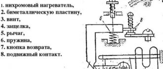
The presence of only two incoming connections for the TRN thermal relay should not scare you, since there are three phases. The unconnected phase wire goes from the starter to the motor, bypassing the relay. The current in the electric motor changes proportionally in all three phases, so it is enough to control any two of them. The assembled structure, the starter with the TRN heater will look like this: Or like this with the PTT:
Let's consider the diagram from the article in which a three-phase motor rotates in one direction and the switching control is carried out from one place with two STOP and START buttons.
The machine is turned on and voltage is supplied to the upper terminals of the starter. After pressing the START button, the starter coil A1 and A2 is connected to the network L2 and L3. This circuit uses a starter with a 380-volt coil; look for a connection option with a single-phase 220-volt coil in our separate article (link above).
The coil turns on the starter and additional contacts No(13) and No(14) are closed, now you can release START, the contactor will remain on. This scheme is called “self-retaining start”. Now, in order to disconnect the engine from the network, you need to de-energize the coil. Having traced the current path according to the diagram, we see that this can happen when STOP is pressed or the contacts of the thermal relay are opened (highlighted by a red rectangle).
That is, if an emergency situation arises and the heater operates, it will break the circuit circuit and remove the starter from self-retaining, de-energizing the engine from the mains. When this current control device is triggered, before restarting it is necessary to inspect the mechanism to determine the cause of the shutdown, and not turn it on until it is eliminated. Often the cause of operation is high external ambient temperature; this point must be taken into account when operating the mechanisms and setting them up.
The scope of application of thermal relays in the household is not limited only to homemade machines and other mechanisms. It would be correct to use them in a heating system pump current control system. The specificity of the operation of the circulation pump is that limescale deposits form on the blades and scroll, which can cause the motor to jam and fail. Using the above connection diagrams, you can assemble a pump control and protection unit. It is enough to set the required rating of the heater in the power circuit and connect the contacts.
In addition, it will be interesting to see a diagram for connecting a thermal relay through current transformers for powerful motors, such as a pump for a water irrigation system for holiday villages or farms. When installing transformers in the power circuit, the transformation ratio is taken into account, for example, 60/5 is when the current through the primary winding is 60 amperes, on the secondary winding it will be equal to 5A. The use of such a scheme allows you to save on components without losing performance characteristics.
As you can see, the current transformers are highlighted in red, which are connected to the control relay and ammeter for visual clarity of the processes taking place. The transformers are connected in a star circuit, with one common point. Such a scheme does not pose any great difficulties in implementation, so you can assemble it yourself and connect it to the network.
Finally, we recommend watching a video that clearly shows the process of connecting a thermal relay to a magnetic starter to protect the electric motor:
That's all you need to know about connecting a thermal relay with your own hands. As you can see, installation is not particularly difficult, the main thing is to correctly draw up a diagram for connecting all the elements in the circuit!
It will be interesting to read:
Tips for installation and setup
Before installation, decide in advance which network you will work on (for example, three-phase or single-phase). It is also important to know exactly which load will require switching on or off. Once you know exactly what you want, feel free to go to the store and buy the appropriate device. Before you install the device and turn off the power to the lighting, check whether the device is working correctly: connect the cord with the plug to it and set the minimum time for operation. Check the voltage at the output contacts with a tester. When installing to a DIN rail, tighten the bolts tightly to prevent the unit from heating up, causing damage, or even causing a fire. Remember that the maximum humidity at which the device can work properly is no more than 80%, and the temperature is from 10-50 degrees.
Settings
- Setting the timer in the device depends on what type of device is in front of us. If we are dealing with a mechanical relay, then setting it up simply consists of switching positions according to the inscription.
- In the electronic one, there is a menu through which all settings are made. As a rule, it begins with setting the day of the week and the current time, and then programming the device itself.
- If this is an electromechanical relay, then it is adjusted using special measuring instruments - potentiometers.
Connection diagram
As a rule, connecting a relay eliminates the use of complex circuits. The main thing, as was said, is to know what load will be required.
Let's consider the simplest scheme:
- Fix the device strictly vertically and tightly enough to the wall.
- Remove the cover and ground the relay.
- Connect the electrical network to the contacts (see picture)
- Contacts 1 and 2 are designed to supply voltage of 220 Volts.
- Designation 4 - used to supply phase from the electrical panel and can be switched with 3 and 5.
- 4 and 5 are normally open, while 3 and 4 are normally closed.
Technical characteristics of photo relay
The level of maximum operating load of a photo relay depends on which devices are connected to it. You need to know that the maximum load of the device is from 1000 to 2300 W, the rated operating voltage is 220 V, and the photorelay threshold limits are 2-2000 lux (lux).
In order for the photo relay you purchased to serve you for a long time and successfully, you need to know from the very beginning what criteria to focus on when purchasing this device and its auxiliary elements. The device can work for a long period of time without creating any problems, or it can break down every week.
We will try to figure out whether it is possible to avoid problems during installation and operation and how to do this. I would like to note that the color of the wires for connecting the relay is different for different manufacturers, so be sure to read the instructions, which show the wiring diagram for the photo relay.
The most popular devices on the modern Russian market are economy class photo relays from manufacturers such as IEK, TDM, EKF, etc.
The photo relay FR-601 and FR-602 with a degree of protection IP44 is offered to us by IEK. Thanks to IP44 protection, the use of these devices is possible outdoors, because IP44 protects us from splashes falling in different directions. The limits within which the response threshold of these photo relays are located can range from 5 to 50 lx. Operating temperatures vary from -25 °C to +40 °C.
You need to know that at an illumination threshold of 5 lux, darkness sets in, while objects are still quite distinguishable. Therefore, in economic conditions, turning on street lighting at such a threshold of illumination does not always justify itself. Deep twilight corresponds to a threshold of 2 lux, when the onset of darkness occurs within 10 minutes.
Photo relay connection diagram
The photo relay automatically turns the lamp on when it gets dark outside, and, conversely, turns off the street lighting when it starts to get light outside. Thanks to this, not only does the service life of the lamps themselves increase, but also significant energy savings occur.
If we talk about the technical characteristics of the photo relay. then it should be noted that the power source is 220 V alternating voltage, and the switched circuit does not exceed 10 A. It should also be said about the working illumination, the level of which is set using the regulator located at the bottom of the relay, and this level can vary from 5 to 50 Lux.
If you want the photo relay to turn on the lamp in cloudy weather or during a slight eclipse, move the regulator to the “plus” side. By moving the regulator to the minus side, you can ensure that the relay operates only when it gets dark.
The photo relay is installed on the wall using a special bracket, which is attached with a screw to the relay itself. The bracket is included in the delivery kit, and when installing it, you should ensure that there is no interference that would prevent natural daylight from reaching the relay. There should also be no trees or other swinging objects in front of the photo relay.
How to connect a photo relay to lighting
Both on the product itself and on the packaging there is a diagram for connecting a photo relay for street lighting. The relay terminals are made of wires with multi-colored insulation to avoid the possibility of their incorrect connection during the connection process. You can guess the purpose of the wires if you know their color markings. In total, three wires come out of the photo relay:
- -black - phase;
- -green - zero;
- -red - commutating phase (to the lamp).
So how to connect a photo relay to lighting? Before you start connecting the photo relay, be sure to read its instructions. To connect the wires, a junction box is used, which is installed on the wall.
Load switching is carried out by interrupting the phase voltage and turning it on. A working “zero” connected to the green wire is necessary for power supply (the operating voltage of the photo relay is 230 V). This product has a rated load current of 10 A (2.2 kW).
If the switched load has a large power, then lighting control requires the use of a very powerful twilight switch. The FR-602 photo relay, whose load current is 20 A, deserves special attention over other devices in the model range of this manufacturer.
Similar materials on the site:
Design and principle of operation
Device design
The operating principle of a classic time relay is easiest to understand after familiarizing yourself with its structure. Any such product contains the following mandatory components:
- module for setting the response time (timer);
- setting organ displayed on the front panel;
- an actuator that operates after a specified time.
The principle of operation can be represented as a sequence of simple operations:
- Once the relay is programmed for a certain period of time, its internal mechanism begins to operate in counting mode.
- After a specified interval, the actuator unit turns the lighting network on or off—supplies or removes power from it.
If a relay is used to control the operation of an electric motor, its operation is based on the same principle. Only the actuating elements are not its own contacts, but powerful contactors of the magnetic starter.
Instruments with mechanical scale
One of the devices that has a mechanical scale is a household timer. It works from a regular outlet. Such a device allows you to control home appliances within a certain time range. It contains a “socket” relay, which is limited by the daily operating cycle.
To use the daily timer, you need to configure it:
- Raise all the elements that are located along the disc circumference.
- Omit all elements that are responsible for setting the time.
- Scroll the disk and set it to the current time period.
For example, if the elements are omitted on the scale marked 9 and 14, then the load will be activated at 9 a.m. and will be turned off at 2 p.m. You can create up to 48 device activations per day.
To do this, you need to activate the button located on the side of the case. If you start it, the timer will start in urgent mode, even if it was turned on.
https://youtube.com/watch?v=VRrU_eYT2l4
Household programmable time relay TS-T01 with ten customizable modes (24/7)
I welcome everyone who stopped by. The review will focus, as you probably already guessed, on the programmable time relay TS-T01, which allows you to turn on/off various electrical equipment at a pre-programmed time with an interval of 1 minute. The relay is designed for connection to household sockets and switching loads with a total current consumption of no more than 16A. The review will include a little testing and disassembly, so if anyone is interested, you are welcome under the cat.
You can buy a programmable time relay TS-T01 in the GearBest store - here
General view of the TS-T01 time relay:
TTX:
— Model name – TS-T01 — Case material — white plastic — Operating voltage — 230VAC — Maximum switching current — up to 16A — Plug/socket type — European standard — Relay operating modes — manual or automatic — Number of programs — 10 programs — Minimum interval — 1 minute - Timer power supply - non-volatile (built-in NiMH battery) - Additional function - time display - operating temperature - from -10°C to +40°C
Package:
The TS-T01 time relay is supplied in a small corrugated cardboard box without any inscriptions:
Inside the box, in addition to the relay, you can only find instructions in English.
Appearance:
The programmable time relay TS-T01 is made in a white plastic case, which houses control electronics with a display, a Euro plug and a socket:
Thanks to the beveled edges, the relay has a pleasant appearance and does not spoil the interior of the house:
Unlike most panel relays installed on DIN rails, this device is a household-class device and is intended to be installed directly into in-house sockets. The power plug and socket are made according to the European standard, i.e. have two pins/sockets and grounding contacts:
On the back of the case there are the main specifications of the device:
Display dimensions – 36mm*15mm, no backlight. Despite this, the readability of the characters is excellent:
The dimensions of the device are about 135mm * 60mm * 73mm, here is a comparison with a box of matches:
Disassembly:
Disassembling the device is quite simple. To do this, you need to unscrew two screws from the back of the case and bend the latches. After this, the body will open into two halves:
As you can see, the power part is made separately from the control part. The microcontroller is powered by a NiMH battery, which in appearance resembles a supercapacitor (green). According to the manufacturer, it provides uninterrupted operation for more than 100 hours. In fact, the charge lasts much longer. When the relay is connected to the network, the battery is recharged. For this purpose, a simple power supply has been added to the circuit. A distinctive feature of the circuit is the use of noise suppression capacitors X2 (yellow) and Y2 (blue):
The power relay is marked AFE BPD-SS-124DM and is designed for switching currents up to 16A at 250V, operating on a voltage of 24V. The power wires are welded to the socket contacts and have a sufficient cross-section of 14AWG (about 2 squares):
The protective rods in the socket can be removed if desired:
Control:
The programmable time relay TS-T01 has 10 independent timers (programs), i.e. On each timer you can set an arbitrary time for turning on and off the load. All controls are located on the front side:
Briefly about management:
— WEEK, HOUR, MINUTE — setting the current time and day of the week (by simultaneously pressing the CLOCK button), as well as the date and time of relay operation
— RES/RCL — reset the current timer (program)
— CLOCK — to set the current time and day of the week, as well as to exit the timer (program) programming mode
— TIMER — alternately entering the timer (program) programming mode. 10 timers (programs) are available. The on timer (program) is shown first (1on), then the off timer (program) (1off). The time and day of operation can be set using the HOUR, MINUTE, WEEK buttons, quick reset with the (RES/RCL) button, exit from timer programming with the CLOCK button
— ON/AUTO/OFF – selection of operating mode (on constantly, by timer, off)
— RANDOM – random operating mode
— CLEAR – reset all settings
In total, for the programmable relay to work correctly, you need to set the current time and day of the week, and then program the timers (programs). To do this, hold down the CLOCK button and press the required WEEK, HOUR, MINUTE button. The WEEK button is responsible for setting the day of the week: Monday (MO), Tuesday (TU), Wednesday (WE), Thursday (TH), Friday (FR), Saturday (SA) and Sunday (SU). The HOUR button is responsible for setting the current hour (24 hour format), and the MINUTE button is for setting the minutes. After setting the date and time, you can proceed to programming the relay. Let me remind you that the device can either turn on consumers at a given time or turn it off, i.e. can either turn on the load for a certain time, or, conversely, turn it off for a certain time. To enter the timer (program) programming mode, you must press the TIMER button. After this, 10 independent timers (programs) will become available in turn. Each program has only two functions: turn on at a specified time and turn off at a specified time. To set the day of operation, in programming mode, press the WEEK button. 16 preset modes are available: all days (every day), only weekdays (working days), only weekends, all days except Sunday, Mon. - Wed - Fri., Tue. – Thurs. – Sat, Mon. – Tue. – Wed, Thu. – Fri. – Sat., Mon. - Wed – Fri. – Sun., and a specific day (7 separate).
I think everything is clear here, but just in case I’ll explain. Suppose we need to turn on some electrical appliance twice a day for 5 minutes (for example, at 12:00 and 20:00) seven days a week (every day). To do this, select the first mode (all days of the week), set the operation time to 12:00 (1on) and the shutdown time to 12:05 (1off) for the first timer (program) and similarly for the second timer (program), only there we set 20:00 and 20:05 respectively. After this, press the CLOCK button or wait 45 seconds. This completes the timer programming. The connected electrical equipment will turn on exactly at 12:00 and 20:00 (according to the clock on the relay) for five minutes every day. The minimum on/off time is 1 minute. There are only 10 programmable timers, but this is enough for home use. If you need to turn on the load with a frequency of 1 hour around the clock, there will be just enough timers (programs), but if the frequency is needed, say, half an hour or 10 minutes, then, alas, there will not be enough timers for a day.
A distinctive feature of the relay is the quick change of operating modes: constantly on, on a timer, off. To select the desired mode, you must alternately press the ON/AUTO/OFF button.
Testing:
I think it’s no secret that the older the city, the more worn out the communications there are, and therefore, in the summer, hot water shutdowns for maintenance or repairs become more frequent. This becomes especially noticeable at the beginning and end of the heating season during routine hydraulic tests. It is for this reason that I purchased a storage water heater, because during the year, in total, there is no hot water for about a month. Moreover, given the neighbors’ habit of saving on everything, even after supplying water, it is impossible to use it normally for a day or two, because it is dirty, cold, and smelly (yes, we have a single-pipe hot water supply, there are a lot of elderly people in the entrance). Considering all the usefulness of water heaters, they do not have any timers of their own, only a thermostat, and in most cases they can “thresh” all day. Of course, I’m exaggerating, but over time, polyurethane thermal insulation begins to lose its properties and the tank retains heat less and less, the heating element turns on more and more often. And in fact, why would a boiler work for half a day when no one is at home, and unattended, too. That’s why I purchased a programmable time relay, so that half an hour before my estimated arrival home, the water would be warm. This is roughly what the whole farm looks like in operation:
In addition, a clock in the kitchen is a very useful thing:
To demonstrate the work, I set the timer to turn on the boiler at 22:24:
Load switch off at 22:25, i.e. it should work for 1 minute:
Don’t forget to turn on the AUTO mode (timer operation), in the photo above the relay is turned off. This is what it all looks like in action:
It can cope with a load of 2kW (current 8-9A), it has been in operation for about 3 months, there are no complaints. I would like to focus on two nuances regarding the work in this implementation, namely faster wear of the tank due to frequent temperature changes and a more energy-consuming mode. To explain the first: it is impossible to make a tank using hot stamping, so the end part and fittings for water inlet/outlet are welded. The most reliable tank is considered to be made of stainless steel, which is welded using argon-arc welding, but in mass production small defects are possible (missing solders, oxidation of part of the seam, etc.). When water is heated, due to the thermal expansion of metals, microcracks may appear, through which a leak may appear as a result of oxidation of the defective part of the seam. Not immediately, of course, but after some time the weakest link will make itself known. This especially applies to tanks made of budget glass ceramics. And even a few magnesium anodes won’t solve anything. The second nuance, in my opinion, is dubious and unconfirmed - the amount of energy spent on heating cold water is slightly more than its constant heating. Sorry, I haven’t checked this fact, but in my opinion, it has a right to life. This mode of operation is more preferable for those who want to extend the life of the water heater, although you will have to fork out for a spare heater, especially in areas with hard water.
Well, a few words about efficiency - with a two-pipe DHW scheme (hot water flows immediately, there is no end cap on the pipe), the water heater is unprofitable. With a single-pipe DHW scheme (hot water must be passed through, because cool water flows first), the water heater is a little more profitable, but it will not pay off its cost soon (our cost for 1kWh is 3.65 rubles, for a cubic meter of hot water it is about 120 rubles). For now, I have settled on using the boiler only when the hot water is turned off and just recently purchased a panel programmable relay (on a DIN rail) for testing, but more about that perhaps later...
Conclusion : a fairly high-quality household programmable time relay with good assembly and circuitry. The appearance is quite pleasant and does not spoil the home interior. The maximum operating current is 16A, but for a long time I would not risk feeding more than 2.2kW (about 10A) through it. Yes, I’m not sure that most household outlets are capable of this, given that the vast majority of electrical goods are Chinese handicrafts, which heat up already at 5-7 amperes. But here it’s not even a matter of conductors, but the relay itself, which is too compact. In any case, up to 10A can be safely used, so I recommend purchasing...
You can find out the current cost of the TS-T01 time relay at this link thousand
Characteristics and selection criteria
First of all, you need to decide on the type of relay used. It must be equipped with a built-in light sensor or an external one. The remote one is small in size, it is easier to protect it from backlighting, the device itself can be installed at home, for example, in a distribution panel. There are even modifications for DIN rail.
A photo relay equipped with a built-in light sensor should be located close to the lighting fixture
Also, during installation, it is important to take into account that the lamp light can affect the photosensor; this should be avoided. A day-night sensor with a built-in element is preferable to use, for example, for solar-powered lamps
Performance characteristics
Classification of degrees of protection
Technical parameters of possible modifications:
- Load power. Each sensor is designed to operate at a specific load power. It is recommended that the power of all lighting fixtures be approximately 20% less than rated. In this case, the equipment will not always be overloaded, which will have a positive effect on its service life.
- Housing protection class. Devices intended for outdoor use must have a protection class of at least IP44. This indicates that dust and water particles larger than 1 mm in size will not be able to penetrate into the housing. Outdoors you can install devices with an even higher protection class, but less is not possible. For home use, you can purchase designs with IP23 protection.
- Mode of use. If the light bulb timer will operate year-round, it must be designed to operate in low and high temperatures. It is recommended to take indicators with a margin in case of abnormal heat or cold weather.
- Supply voltage. It can be either 220V or 12V. The choice mainly depends on the type of voltage that powers the street lighting. 12V lighting fixtures can also be used with rechargeable batteries.
Customization options
Setting the sensitivity of the photo relay
There are several adjustments that will allow you to customize the operation of the sensor for a specific situation. Equipment settings at the initial stage of use are carried out manually by turning the required regulator. It is almost impossible to achieve the same parameters.
- Adjustable light range. Thanks to this parameter, the lighting is set at which the relay closes and opens the contacts. The range can vary from 2 to 100 Lux in complete darkness, and from 20 to 80 Lux at twilight.
- The response threshold allows you to reduce or increase light sensitivity. It is recommended to reduce this parameter in winter, when there is snow on the ground and the sensors react to it. It is also reduced if brightly lit objects are located in close proximity.
- Delay, measured in seconds, for turning off and on. By increasing the shutdown delay, the number of false alarms is reduced, for example, when light from a car's headlights hits the sensor. The turn-on delay, in turn, will prevent the lighting device from being turned on when it is darkened by the shadow of a bird or a cloud.
Kinds
According to their design, time relays are divided into:
The monoblock is a completely independent device, with its own housing, built-in power supply and special sockets for connecting any equipment. Those involved in photo printing are well familiar with this type of relay.
Built-in relays are a simplified version of monoblock relays. They do not have their own housing and power supply, since they are needed in order to create more complex devices. They are used as additional elements and therefore they are placed in the same housing with other elements of the manufactured device. A classic example is a timer in a washing machine, microwave, oven, etc.
Modular (with control contact) - this type has standard dimensions and is installed on a DIN rail in the distribution panel.
In addition, time relays are also classified depending on the operating principle (how exactly the time interval is created):
- Time relay with clock mechanism. This type was the first to be manufactured and is still considered one of the most reliable, since its properties are not inferior to pneumatic devices. Their operation is practically independent of voltage power, how often it is applied, or temperature changes. In everyday life, this type of relay is found in mechanical alarm clocks, kitchen timers, and in some washing machines a mechanical program relay is also found.
- With electromagnetic retardation.
Used in circuits oriented to constant voltage. The delay is carried out by creating an auxiliary magnetic flux, regulated by changing the tension value of the return spring. The adjustable value is up to five seconds. A significant disadvantage of this type of relay is that the time delay depends on temperature changes. Electric relay - Vacuum (electromechanical). This type is used where an electrical or pneumatic signal is required to control whether the vacuum level has been reached.
- Motor. Includes motor with gearbox and electrical contact. The time delay capability ranges from 10 seconds to tens of hours.
- Relay with hydraulic or pneumatic retardation. Time intervals here are regulated by increasing or decreasing the supply of liquid and air into the working process. One of the advantages is that the slowdown does not depend on the voltage, supply frequency and temperature changes. Also, adjusting the delay is not difficult.
- Electronic relay. The most widely used type of time relay, gradually replacing mechanical analogues. The advantages of this type are its small size, weight, high accuracy, reliability and wide selection of operating programs.
Electronic relays are divided among themselves based on the timing technology:
- Digital—voltage is applied to the power supply, which causes the master oscillator to start, which then sends pulses to the counter. The latter, in turn, calculates these pulses until they are equal to the required number of pulses that is specified in the system. Then, a signal is sent to the output amplifier controlling the relay and the counter stops counting pulses. As soon as the voltage is removed from the power supply, the relay will return to its original state. Such radios are capable of delaying time for tens of hours with minimal error. The main disadvantage is the high cost.
- Analog - to delay time, a capacitor is used, to which voltage is applied when the contacts are closed. This voltage is monitored by a special device that compares it with the previously specified one. If they match, the device sends a signal so that the relay switches. The maximum shutter speed here is 10 seconds. This type is superior to digital in that it does not require precise programming and is easier to use.
Conclusions and useful video on the topic
The video discusses the possibility of using a modular device, where there are two independent time-switching devices. The scheme provides for turning on two household appliances, setting their operation in time intervals and other functions.
Of course, all existing modifications of time relays cannot be covered in one modest review. To review the entire range of devices, you would need to write an entire book. Actually, reference books on different types of timers are available, and if you wish, you can always find the necessary information.
Do you have anything to add, or do you have any questions about the operation, selection, connection and configuration of a time relay? You can leave comments on the publication and participate in discussions. The contact form is located in the lower block.
Application
If you use such a device, share in the comments to the article what purposes you use it for; this information may be useful to someone.
See also on the topic:
Time timer, electronic and electromechanical.
Photo relay for street lighting: types, application, connection diagram.
Pulse relay. Connection diagram and operating principle.
The simplest 12V timer at home
The simplest solution is a 12 volt time relay. Such a relay can be powered from a standard 12v power supply, of which there are many sold in various stores.
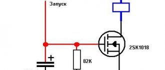
The figure below shows a diagram of a device for turning on and automatically turning off a lighting network, assembled on one integrated counter of the K561IE16 type.
Drawing. A variant of a 12v relay circuit that turns on the load for 3 minutes when power is applied.
This circuit is interesting in that the flashing LED VD1 acts as a clock pulse generator. Its flicker frequency is 1.4 Hz. If you cannot find an LED of this particular brand, you can use a similar one.
Let's consider the initial state of operation, at the moment of supplying 12v power. At the initial moment of time, capacitor C1 is fully charged through resistor R2. Log.1 appears at pin No. 11, making this element zeroed.
The transistor connected to the output of the integrated meter opens and supplies 12V voltage to the relay coil, through the power contacts of which the load switching circuit is closed.
The further principle of operation of the circuit, operating at a voltage of 12V, is to read the pulses coming from the VD1 indicator with a frequency of 1.4 Hz to pin No. 10 of the DD1 counter. With each decrease in the level of the incoming signal, there is, so to speak, an increment in the value of the counting element.
When the 256th pulse arrives (this equals 183 seconds or 3 minutes), a log appears on pin No. 12. 1. This signal is a command to close transistor VT1 and interrupt the load connection circuit through the relay contact system.
At the same time, logic 1 from pin No. 12 is supplied through diode VD2 to clock leg C of element DD1. This signal blocks the possibility of receiving clock pulses in the future; the timer will no longer operate, until the 12V power supply is reset.
The initial parameters for the operation timer are set in different ways by connecting the transistor VT1 and the diode VD3 indicated in the diagram.
By slightly transforming such a device, you can make a circuit that has the opposite principle of operation. The KT814A transistor should be changed to another type - KT815A, the emitter should be connected to the common wire, the collector to the first contact of the relay. The second relay contact should be connected to a 12V supply voltage.
Drawing. A variant of a 12v relay circuit that turns on the load 3 minutes after power is applied.
Now, after power is applied, the relay will be turned off, and the control pulse that opens the relay in the form of logic 1 output 12 of element DD1 will open the transistor and supply 12V voltage to the coil. After which, the load will be connected to the electrical network through the power contacts.
This version of the timer, operating from a voltage of 12V, will keep the load disconnected for a period of 3 minutes, and then connect it.
When making the circuit, do not forget to place a capacitor with a capacity of 0.1 μF, designated C3 in the circuit and a voltage of 50V, as close as possible to the supply terminals of the microcircuit, otherwise the counter will often fail and the relay dwell time will sometimes be less than it should be.
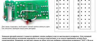
In particular, this is programming the exposure time. By using, for example, a DIP switch as shown in the figure, you can connect some contacts of the switches to the outputs of the counter DD1, and combine the second contacts together and connect them to the connection point of the elements VD2 and R3.
Thus, using microswitches you can program the relay delay time.
Connecting the connection point of elements VD2 and R3 to different outputs of DD1 will change the dwell time as follows:
| Counter leg number | Counter digit number | Exposure time |
| 7 | 3 | 6 sec |
| 5 | 4 | 11 sec |
| 4 | 5 | 23 sec |
| 6 | 6 | 45 sec |
| 13 | 7 | 1.5 min |
| 12 | 8 | 3 min |
| 14 | 9 | 6 min 6 sec |
| 15 | 10 | 12 min 11 sec |
| 1 | 11 | 24 min 22 sec |
| 2 | 12 | 48 min 46 sec |
| 3 | 13 | 1 hour 37 min 32 sec |