Good day to all. Today we continue the topic about rectifiers and we’ll talk about smoothing filters for rectifiers
. Smoothing filters are connected between the rectifier and the load to reduce the variable components (ripple) of the rectified voltage. These filters are made of inductive elements - chokes and capacitive elements - capacitors. The simplest anti-aliasing filter can consist of only one element, for example an inductor or a capacitor. In small-sized equipment with relatively low power, inductive filter elements can be replaced by active ones (resistors).
Smoothing filters are primarily characterized by a smoothing coefficient q, which is the ratio of the ripple coefficients at the input S0 and the output S0H of the filter:
To assemble a radio-electronic device, you can pre-make a DIY KIT kit using the link.
Inductive Antialiasing Filter
It is used in low-power rectifiers, but can be part of complex multi-section filters. The inductor parameters should be selected so that the active winding resistance rdr is much less than the load resistance (rdr << Rn), and the inductive resistance Xdr = 2πfпLф at the pulsation frequency fp is much greater than Rn (Xdr >> Rn). In this case, almost the entire DC component of the voltage will be applied to the load, and the AC component will be applied to the inductor.
Using a given smoothing coefficient q, you can calculate the required inductance of the smoothing filter
The inductive filter is simple, cheap, and has low power losses; The filter smoothing coefficient increases with increasing inductance of the inductor, the number of phases of the supply voltage and with decreasing load resistance. Therefore, inductive filters are usually used in conjunction with multiphase powerful rectifiers. When the load is disconnected or its resistance changes abruptly, overvoltages may occur; in this case, it is necessary to include protective devices, such as arresters, in parallel with the inductor winding. In low-power single-phase rectifiers, the inductive filter can be a part of a more complex filter.
How to choose and buy a filter
All of the information listed above should help you decide on the type of device directly in the store.
However, pay attention to two more questions:
- total power consumption of the connected load;
- the presence of sockets in the housing that do not provide voltage filtering, but work as a simple extension cord (such a device is also found).
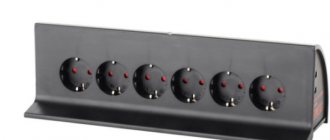
For the device shown in the photo, the maximum permissible load is marked on the back of the case and is limited to 10 amperes.
For normal operation, we recommend having a reserve of about 30 percent minimum, that is, loading this model with no more than 7 amperes. This is quite enough for complex household appliances with electronics. After all, there is no need to power electric boilers, heaters, incandescent lamps and electric motors through a surge protector. They operate normally on voltage with high frequency noise.
We also recommend watching the CompsMaster owner’s video “Choosing a surge protector.”
Now it’s convenient for you to ask questions on the topic and share this material with friends on social networks.
Useful products
- Disappearing ink pen
- Sleeping bag
- Electric shaft with remote control for roller blinds
Capacitive anti-aliasing filter
Capacitive anti-aliasing filter
consists of a capacitor Sf connected in parallel with the load resistance Rн. The principle of operation is the accumulation of electrical energy by the filter capacitor and the subsequent release of this energy to the load. The charge and discharge of the filter capacitor occurs with the pulsation frequency fп of the rectified voltage.
To calculate the capacitance of the anti-aliasing filter capacitor
you can use the following formula
, Where
the resulting capacitance value is expressed in microfarads, SOH is the ripple coefficient in percent, %; RH – load resistance in ohms, Ohm; fc – network frequency in hertz, Hz; m is the number of half-cycles used during rectification per period of the network voltage, m = 1 – for half-wave, m = 2 – for full-wave.
It is best to use a capacitive filter in conjunction with single-phase and low-power rectification circuits.
Precautionary measures
If we talk about precautions, then first you should remember that the homemade surge protector that you want to assemble from available parts is a rather complex technical device. And without knowledge in the field of electronics, quite extensive at that, it is simply impossible to do it correctly. In addition, all work on the creation or modification of an existing device must be carried out exclusively in compliance with all safety measures. Otherwise, there is a high risk of electric shock, which can be not only dangerous, but also fatal.
It should be remembered here that the capacitors used to create network filters are designed for fairly high voltage.
This allows them to accumulate a residual charge. For this reason, a person can receive an electric shock even after the device has been completely disconnected from the electrical network. Therefore, during operation there must be a resistance connected in parallel. Another important point is that before working with a soldering iron, you should make sure that all elements of the surge protector are in good condition. To do this, you should use a tester, which needs to measure the main characteristics and compare them with the declared values.
A final important point that is worth mentioning is that cables should not be allowed to cross, especially in areas where the potential for heating could be very high. For example, we are talking about exposed contacts, as well as surge protector resistors. Yes, and it would not be superfluous to make sure before connecting the device to the network that there will be no short circuits. This can be done using a tester. As you can see, it is possible to make a surge protector with your own hands. But to do this, you must clearly know what actions you are performing and have some knowledge in the field of electronics.
Anti-aliasing RC filters
In low-power rectification circuits, the filter choke can be replaced by an RF resistor. These types of filters are called RC filters
The calculation of the anti-aliasing RC filter must take into account the following conditions:
Filter smoothing factor
The resistance of the resistor RF is usually set within the range RF = (0.15...0.5)RH; The efficiency of a resistive-capacitive filter is relatively small and usually amounts to 0.6...0.8, and at ηф = 0.8 RF = 0.25RH. Capacitance Cf (in microfarads), provides the required smoothing coefficient q at a network frequency fC = 50 Hz, found from the expression
Advantages of resistive-capacitive filters: small dimensions, weight and cost; disadvantage - low efficiency.
Ways to Improve the Filter Circuit
There are many options for improving the network filter circuit. One of them is ingenious and allows you to significantly save energy consumption. The essence of the method is as follows:
- Open the housing of the multi-connector SF extension cord.
- One of the current-carrying busbars is cut.
- The segments are connected to a 5 volt relay, designed for switching current 3A, 250 V.
- The other two relay contacts are connected by wires to a USB connector at the end.
- The connector is connected to the USB input of the TV.
The result is a controlled power system consisting of a TV, a digital set-top box and a satellite dish power supply. If previously, when the TV was turned off, all parts of the system remained in standby mode, then with the upgraded filter they are completely turned off. As soon as you turn on the TV using the remote control, all the switched devices are also activated and vice versa.
In another case, they take the path of adding an LC filter to the SF, which, in addition to suppressing interference from the network, reduces mutually occurring electrical interference from connected consumers.
A standard varistor (470 V) often does not trip the automatic fuse. It is replaced with a similar device designed for a voltage of 620 V. This allows you to suppress interference from a running washing machine, vacuum cleaner and other powerful electrical equipment.
Home craftsmen equip surge protectors with audible alarms. When the voltage level in the network exceeds 280 V, the filter notifies you with a signal.
Multi-link anti-aliasing filters
If using an inductive-capacitive filter it is necessary to ensure a ripple smoothing coefficient of more than 40...50, then instead of a single-section filter it is more advisable to use a two-section smoothing filter
.
Filters with three or more sections
in practice they are rarely used. In the general case, the smoothing coefficient of a multi-link filter is equal to the product of the smoothing coefficients of individual links: q = q'q''q''' ...
Smoothing inductive-capacitive filters are quite simple and effective in rectifier devices of medium and high power. However, the mass and dimensions of such filters are very significant, the smoothing coefficient decreases with increasing load current, and the filters are ineffective when slow changes in the mains voltage occur. Inductive filter elements are sources of magnetic stray fields, and together with parasitic capacitive elements they create oscillatory circuits that contribute to the appearance of transient processes.
How to make a filter at home
Making a surge protector with a switch with your own hands is not very difficult; in terms of efficiency, this device will not be inferior to Sven Optima Base 5 m Black, Power Cube, Belkin (Belkin), APC PF8VNT3-RS.
Let's look at the step-by-step instructions:
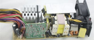
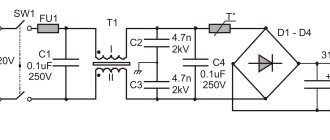
The extension cord consists of two fuses, one acts as a switch (different ones are connected in the photo). And the other - a circuit breaker, a varistor, contact connections. The varistor is the main protection of all stabilizers. Separately, it should be noted that most schemes are based on the principle of connecting a simple extension cord and a filter; (the number 14 doesn’t mean anything, most likely it’s just a batch number)
C2 is a capacitor; it must have long wires, because otherwise, you will not be able to install the contact plates. But keep in mind that cords that are too long will reduce the effectiveness of the extension cord; If you install homemade network filters for a refrigerator, audio equipment (cassette recorders, home theaters), televisions and other office equipment, then you need to mount a ferrite washer near the network cable; it will prevent interference; Next you need to select varistors. It is believed that the optimal size is 471 with a diameter of 6 to 10 millimeters; Next come the electrical resistors in the circuit R1, R2. To prevent household appliances from transmitting interference, you need to select powerful resistors with the maximum allowable resistance. To calculate this data, you need to calculate the ratio of the power consumed by all devices included in the filter. For laptops, the average resistor should be 5 ohms; for more powerful devices, two-watt resistors are used; Now we mount the chokes, in the drawing L1, L2. The main requirements put forward are: a ferrite core (pulse filters without it have poor inductance), an open-class armature or an air gap
It is very important that the inductor has the highest current equal to the coil current; The DC consumer must be equipped with capacitors (C1, C2); depending on the size of the unit, one or both capacitors can be installed. And the last thing to install is resistor R3. We select it depending on the required kW or W
It should be noted that these units are seriously loaded by the power supply system, so they must be quite large and powerful; If necessary, install the device on a stand. When finished, perform a throughput test.
Various amateur radio circuits for assembling a surge protector for equipment:
Photo - Original extension cord diagram
Photo - Surge filter
Photo - Surge filter circuit
Using this information, you can make a linear machine with your own hands. In this case, power supplies can have any power and frequency readings; the main thing is to calculate the throughput of individual parts.
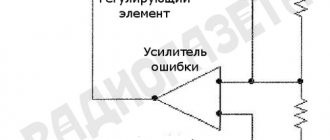
Transistor anti-aliasing filter
Transistor filters
Compared to inductive-capacitive smoothing filters, they have smaller dimensions, weight and a higher ripple smoothing coefficient.
Filters can be made according to circuits with a power transistor connected in series or in parallel with respect to the load resistance, as well as with a load RH connected to the collector or emitter circuit of the transistor. The disadvantage of filters with a load in the collector circuit is the large change in output voltage when the load resistance changes. Therefore, filters are more often used in which the load resistance is included in the emitter circuit of the power transistor.
Filter with series transistor
Transistor smoothing filter with serial connection of a transistor and a load in the emitter circuit
equivalent to a U-shaped LC filter. Its operating principle is based on the fact that the collector and emitter currents of the transistor in amplification mode are practically independent of the collector-emitter voltage. If you select the operating point of the transistor on the horizontal section of the output current-voltage characteristic, then its resistance for alternating current will be significantly greater than for direct current.
Transistor filter
In the circuit, the base current of the transistor VT is set by the resistor Rb. Capacitor Sat of a sufficiently large capacity eliminates the ripple voltage at the emitter-base junction. Therefore, the alternating component of the ripple voltage is applied to the base-collector junction and is allocated to the transistor VT. There is practically no alternating component in the collector and emitter current, so the ripple in the RH load is also very small.
The smoothing coefficient of the transistor filter is greater, the greater the current transfer coefficient of the transistor VT and the greater the value of the ratio
that is, the lower the ripple voltage at the emitter-base junction of the power transistor.
Composite transistor
To more successfully fulfill these relationships, the capacitor Sb can be replaced with a single- or two-section RC smoothing filter, and to increase the current transfer coefficient, the transistor VT can be made as a composite
Transistor filter with zener diode
a zener diode connected to the base circuit of the transistor works even more efficiently.
The lower the DC voltage drop across the power transistor, the greater the efficiency of the transistor filter. However, the amplitude of the alternating voltage component on the transistor should not exceed the value of the direct voltage across it, otherwise the filter will lose its functionality.
Parallel transistor filter
Filter with a ballast resistor and parallel connection of a transistor Filter with a ballast resistor and series connection of a transistor
Transistor filters with a ballast resistor Rbl and parallel connection of a transistor
relative to the load, unlike
circuits with series connection
, it is used at a relatively small rectified voltage (tens of volts). The operating mode of the transistor VT - the minimum current value IK.min - is set by the appropriate choice of resistances R1 and R2. The alternating voltage component in this circuit is applied to the emitter-base junction of the transistor VT, amplified and released at the ballast resistor Rbl. This component turns out to be in antiphase with the alternating voltage component, released on Rbl when the load current flows directly. By choosing Rbl and IK.min, you can achieve their full compensation. The amplitude of the alternating component of the transistor current VT must be less than the flowing direct current IK.min, otherwise the circuit will be inoperable. The current IK.min should not be very small, since otherwise an increase in resistance Rbl will be required, which will lead to a decrease in the filter efficiency. Too much current is also impractical, since the power loss on the transistor increases and the efficiency decreases.
The smoothing coefficient of a parallel transistor filter will be greater, the greater the resistance Rbl, the capacitance of capacitors C1 and C2, and the steepness of the current-voltage characteristic of the transistor. The disadvantage of a transistor filter with parallel connection of a transistor is a significant change in the average value of the collector current of the transistor when the average value of the rectified voltage supplied to the filter input changes. This leads to a decrease in filter efficiency.
It should be remembered that transistor filters do not provide stabilization of the constant component of the rectified voltage, and when the load current changes, the ambient temperature and the influence of other destabilizing factors, they introduce additional instability of the rectified voltage.
Theory is good, but you need to practice it all practically. YOU CAN TRY HERE
Surge filters often use tricky capacitors with inscriptions that are incomprehensible to many - X1, Y2, etc. These are noise suppression capacitors. This article will help you understand why they are needed and how they differ from “just capacitors.”
There has always been enough interference in the network - at first it appeared from brushed motors, and now it is produced on an industrial scale by switching power supplies. The fact that interference is bad is not worth repeating once again. The mains voltage in extreme cases looks something like this:
It can be seen that this is very different from the sinusoid that should be there. In order to get rid of interference, you need to create an unobstructed path along which the interference current can return to the source. Typically, this path, according to Murphy's law, lies through the most sensitive equipment. Our task is to make sure that the interference does not “want” to get into the “tender places” of our circuits, but to allow the interference current to flow where it “wanted” to flow (to the neutral, for example). On the other hand, you can avoid bringing the network to a deplorable state without releasing interference outside the device.
In order to reduce interference, filters are used. The type of filter and even its location depends on the specific case. For example, if interference is created by one source (an engine, for example), then it is best to place the filter closer to this source - short-circuit the interference current (as in the figure above).
If interference is created by a distributed circuit in a metal case (computer power supply), then it is better to place the filter as close as possible to the power cord - short-circuit the interference current inside the case and connect the case to the “cleanest” place in the circuit so that it does not radiate itself.
The figure shows a typical filter circuit for a computer power supply. Red shows the path of radiated interference, and green shows the path of interference transmitted through the wires.
The interference has two components – in-phase and anti-phase.
The antiphase component of the interference is the interference voltage between phase and neutral. To suppress it, type X capacitors are used. The name X itself comes from the English “across-the-line”, the letter X looks like a cross (“cross”). In the figure above, this is the capacitor - C1.
These capacitors are subject to the following requirements: they must withstand the maximum permissible surges in the network, not catch fire when they fail, and not sustain combustion.
There are two main subclasses of X-capacitors currently in use – X1 and X2.
- X1 – used in industrial devices connected to a three-phase network. These capacitors are guaranteed to withstand a voltage surge of 4kV.
- X2 is the most common class of capacitors. Used in household appliances with a rated network voltage of up to 250V, withstand a surge of up to 2.5kV.
The capacitance of X capacitors varies from 0.1uF to 1uF. What capacitance you need to choose for this particular device can only be determined with an oscilloscope.
The common mode component of the interference is the interference voltage between both mains wires and the device body. Understanding what it is and why it is needed is a little more difficult.
Consider a typical switching power supply. There is always a stray capacitance between the primary and secondary windings of transformer T1 (drawn in green). Let's imagine that there is no capacitor C7 yet. High-frequency ripples freely penetrate from the drain of the transistor (the noisiest place in the circuit!) to the secondary winding through the green capacitance. Thus, throughout the entire output part of the power supply there is ripple (at the frequency of the power supply) relative to ground and both network wires. The voltage of these ripples can reach thousands of volts. Our mega-sensitive device will emit these pulsations into the air, and emitting interference is the same as catching interference only with the opposite sign. The device will be bad.
Now let's add capacitor C7. The interference current that leaked through the green capacitor can now return to where it came from along a shorter and less complicated path than in the previous case, and it no longer wants to flow into our mega-sensitive device!
Notice that capacitor C7 now connects the mains to the power supply output! But this is dangerous! A person who touches simultaneously the output of such a power supply (to the body of the device) and the ground (to a heating battery, for example), will receive a noticeable, but not terrible blow. What happens if capacitor C7 breaks? That's right, the output of the power supply will become an “electric chair”. That is why Y-type capacitors were made - they are designed to work in places where their failure threatens people's lives .
Y-type capacitors are divided into 2 main classes
- Y1 – Operate at rated mains voltage up to 250V and withstand pulse voltage up to 8kV
- Y2 – The most popular type, can be used at mains voltages up to 250V and can withstand pulses of 5kV
Now some facts.
- Y type capacitors can be used instead of X type capacitors, but X type capacitors cannot be used instead of Y type capacitors.
- Y type capacitors usually have a much lower capacitance than X type capacitors.
- If for X type capacitors the more capacitance the better, then the capacitance of Y type capacitors should be chosen as small as possible. The typical value of 2.2nF already beats quite well if you grab the power supply output and the battery.
- Despite all safety measures, manufacturers recommend unplugging the plug from the socket when you leave the house for a long time.
I also recommend reading the document
CAPACITORS FOR RFI SUPPRESSION OF THE AC LINE: BASIC FACTS
rfi_fact.pdf
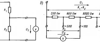
What is an electric filter
An electrical filter is a device for selecting desirable components of the spectrum (frequencies) of an electrical signal and/or suppressing unwanted ones.
For other frequencies that are not included in the passband, the filter creates large attenuation, up to their complete disappearance. The characteristics of an ideal filter should cut out a strictly defined frequency band and “squeeze” other frequencies until they are completely attenuated. Below is an example of an ideal filter that passes frequencies up to a certain cutoff frequency value.
In practice, such a filter is impossible to implement. When designing filters, they try to get as close as possible to the ideal characteristic. The closer the frequency response characteristic is to an ideal filter, the better it will perform its signal filtering function.
Filters that are assembled only on passive radio elements, such as an inductor, capacitor, resistor, are called passive filters . Filters that contain one or more active radio elements, such as a transistor or, are called active filters .
In our article we will look at passive filters and start with the simplest filters, consisting of a single radio element.
Industrial and homemade filters for a three-wire power system
Among the mass-produced products there are quite useful technical solutions that the home craftsman should pay attention to.
Brief overview of useful functions of factory models
One of the popular developments, widely represented in the trade, is the Pilot series of filters of different designs.
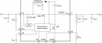
The circuit diagram of the Pilot surge protector is shown in the picture to make it easier to understand its capabilities.
I will dwell on the tasks that Pilot XPro, specially created for comfortable work, extending the life of connected consumers and reducing electricity consumption, is designed to solve. This:
- protection against surge voltages by varistors;
- prevention of high-frequency interference by inductive-capacitive reactances;
- power management through the introduction of the Master Control ;
- protection against overvoltage associated with zero loss;
- smooth switching off and switching on of equipment under load with the Zero Start due to the elimination of current surges by the built-in circuit ;
- automatic switching on of consumers after elimination of emergency power failure;
- two levels of protection against current overloads or short circuits due to a fuse and a bimetallic release;
- indication of network connection and supply voltage level;
- temperature control and automatic shutdown when overheating.
Master Control function defines one socket as the main socket (as a master socket). The main consumer with a power of more than 50 watts is connected to it, for example, a computer system unit.
When it is turned on, the automation simultaneously powers three other sockets with peripheral equipment. It also turns them off when power is removed from the main unit.
There are sockets on the case that are not controlled by microprocessor automation. They are used for lighting, telephones, and other equipment.
You can find out more detailed information about this equipment in a short video by the owner of ZIS Company.
Simple surge protector device
There are two types of SF:
- Built-in.
- Stationary – multi-channel.
Built-in
Compact SF boards are part of the internal structure of various electronic equipment. They are equipped with computers and other complex equipment.
Built-in network filter board
The photo shows the SF device. The following parts are installed on the board:
- VHF – capacitor;
- toroidal throttle;
- additional capacitors;
- varistor;
- induction coils;
- thermal fuse.
A varistor is a resistor with variable resistance. If the standard voltage threshold (280 V) is exceeded, its resistance can decrease tens of times. The varistor performs the function of surge protection.
Stationary – multi-channel
The device body has several sockets. Thanks to this, it is possible to connect all existing electrical equipment in one room to one outlet through a filter. To remove high-frequency radio interference, a simple LC filter is used. Fireproof thermal fuses prevent power surges. Some models use disposable fuses.