Types of power supplies
There are two principles for converting electricity in devices: based on an analog transformer and on switching power supplies (UPS).
Transformer power supplies.
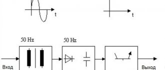
The peculiarity of power supplies of this type is the use of a power transformer to change the voltage in the network. The devices reduce the amplitude of the sinusoidal harmonic and direct it to a rectifier consisting of power diodes. Smoothing occurs due to a parallel connected capacitance. The final stabilization of the supply voltage is carried out in a semiconductor circuit with resistors.
Until recently, transformer converters were the only ones of their kind, but had disadvantages:
- heavy weight and large dimensions;
- high cost, often many times higher than the price of other network components.
Pulse power supplies.
The design of the device does not include a step-down transformer. Almost all modern equipment uses switching power supplies as the most compact and efficient ones.
Advantages and disadvantages of switching power supplies
Main advantages of UPS:
- Light weight and compact dimensions.
The reduction in device dimensions is due to the transition from the use of heavy power transformers. The UPS does not have linear control systems that require the installation of large cooling radiators. Increasing the frequency of processed signals also made it possible to reduce the size of capacitors. - High efficiency.
Low-frequency transformers are characterized by significant energy losses in the form of heat, which is generated as a result of electromagnetic transformations. In a UPS, maximum losses occur in the power switch cascade during transient processes, and the rest of the time the transistors are stable. Energy losses are kept to a minimum. The efficiency of the devices reaches 98%. - Wide range of input voltages.
The scope of application of the devices has been significantly expanded. Switching technologies allow the use of power supplies in networks with different electricity standards. - Built-in protection systems.
Most models have automatic protection against short-circuit currents, emergency load shutdown systems, etc. Protective devices are reliably integrated into the design of the units thanks to the use of miniature digital semiconductor modules. - Affordable price.
The UPS element base is constantly being unified. The cost of the main components of devices that are mass-produced on automatic machines is reduced. Additional cost reductions are achieved through the use of lower power semiconductors.
The disadvantages of the UPS are:
- Power restrictions.
There are contraindications for both high and low loads. If the current in the output circuit drops below a critical value, the unit begins to generate voltage with distorted characteristics, or the triggering circuit completely fails. - Presence of high frequency interference.
The blocks produce them in any design. High-frequency interference is transmitted into the environment, so it is necessary to additionally address the issue of suppressing it. For some types of sensitive digital equipment, the use of a UPS is not possible for this reason.
Switching power supplies are gaining more and more living space. Their reliability is growing, and those disadvantages that are characteristic of pulsed energy converters are more than compensated for by their undoubted advantages. Now they are beginning to be used in areas where linear power supplies have traditionally been used.
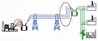
One of the disadvantages of switching power converters is that they are a source of high-frequency interference that penetrates into the primary AC network. This, in turn, can lead to unstable operation of other equipment connected to the same phase of the primary network as the pulsed source. In this regard, absolutely any power supply must include input noise suppression circuits that ensure its protection from interference from the primary network, as well as protection of the primary network from high-frequency interference from a pulsed source. In addition, these circuits can perform functions of protection against high voltages and high currents.
The alternating current of the network at the first stage of conversion must be rectified using a diode bridge. This diode bridge is supplied with alternating current through a power switch, a power fuse, a negative temperature coefficient thermistor (NTC) and a noise filter. In the vast majority of power supplies, the design of the input circuits is the same, and such a typical circuit diagram of the input circuits is shown in Fig. 1.
Rice. 1
A thermistor with a negative TCR serves to limit the surge of charging current through capacitor C5 at the moment the power source is turned on. When the power supply is turned on, at the initial moment of time, the maximum charging current of capacitor C5 flows through the diode bridge, and this current can damage one (or more) rectifier diode. Since in a cold state the resistance of the thermistor is several Ohms, the current through the rectifier diodes of the bridge is limited to a level that is safe for them. After a certain period of time, as a result of the flow of charging current C5 through the thermistor, it heats up, its resistance decreases to fractions of an Ohm and no longer affects the operation of the circuit.
This solution to the problem of limiting the charging current surge using an element with a nonlinear volt-ampere characteristic is used quite often, since the circuit turns out to be the simplest and cheapest compared to other options. In addition, it provides minimal losses and high reliability, which is why it is used in almost all power supplies. The limiting thermistor, like any heated element, has thermal inertia. This means that in order for it to restore its restrictive properties, after turning off the power supply from the network, some time must pass (about several minutes), that is, it must cool down. In this case, the next time the power supply is turned on, the charging current surge will also be limited. And this is an additional condition, because of which it is strongly recommended to wait one or two minutes before turning on the power source again after turning it off, although in practice there are often situations in which it is necessary to turn off the power source and immediately turn it on again.
Thermistors quite often fail due to breakdowns of the power transistor or breakdowns of rectifier diodes. Malfunctions of thermistors are quite obvious, since they usually burn out with physical damage to the housing, that is, the housing of the element breaks and traces of soot are visible on it. If the thermistor burns out, the repair specialist can use several options to solve the problem:
— Replacing the thermistor with a similar one is the most optimal solution.
— Replace the thermistor with a conventional resistor of low resistance (several Ohms) and high power (about 5 W) - in this case, such a resistor will limit the current through the rectifier during the entire operation of the power supply, but will generate a fairly large amount of heat.
— Replace the thermistor with several turns of nichrome wire - such an element will perform a general current limitation, and the turns will contribute to a smooth increase in current. However, it is worth noting that such a solution cannot be called optimal, and it is better to refrain from using it.
— Replacing the thermistor with a jumper - this repair method is not recommended (and some experts categorically warn against replacing the thermistor with a jumper), but in some situations this has to be done. In addition, if during repairs it was necessary to replace the rectifier diodes and install more powerful ones (for example, KD226), then, as practice shows, the charging current for such diodes is not terrible; the circuit is quite functional without a thermistor.
It should be noted that some manufacturers place a limiting thermistor between the “-” diode bridge and the common wire of the primary part (Fig. 2).
Rice. 2
Some power supplies do not use thermistors, but use high-power limiting resistors (usually white and parallelepiped-shaped). These resistors have a resistance value of several ohms and a power of 5–10 W. As noted earlier, such a resistor provides current limitation not only at the moment of switching on, but constantly while the power source is operating. Therefore, quite a lot of power is dissipated on the resistor, and it gets very hot.
Mains fuse FU1 is designed to protect the supply network from overloads that occur when the mains rectifier or power transistor malfunctions. A structural change in the fuse position during repair is undesirable, as this may lead to the appearance of network electromagnetic interference.
The input noise suppression filter has the property of bidirectional noise suppression, that is, it prevents the penetration of high-frequency impulse noise from the network into the power supply and, conversely, from the power supply into the network. This impulse noise can have a significant amplitude. Network interference is mainly of an industrial basis and is created by arc and contact welding equipment, power ballasts, drive motors, medical equipment, etc. The interference generated by the power supply is caused mainly by the pulsed operating mode of the power transistor and rectifier diodes. Interference generated by both the power network and the power supply can be divided into two types: symmetrical and asymmetrical.
Symmetrical (differential) interference is the voltage between the power wires. This interference is measured between the two poles of the power buses.
Unbalanced (common mode) interference is the voltage between each wire and the power supply housing (Fig. 3).
Rice. 3
To analyze the operation of the noise suppression filter, consider the case when symmetrical noise affects the power supply circuit.
The interference EMF is applied to the input of the power source between the phase and neutral wires on the network side. Capacitor C1 represents a very high resistance for the mains frequency supply current (50Hz), and therefore this current does not branch off through capacitor C1. For pulsed high-frequency interference current, this capacitor, on the contrary, has a very low resistance, and therefore most of the interference current is closed through it .
However, one capacitor C1 is not enough to completely suppress the interference. Therefore, the two-winding inductor T1 (neutralizing transformer) is then turned on, windings I and II of which have the same number of turns and are wound on the same core. The winding direction of both windings is consistent. It follows from this that the useful current of the mains frequency, flowing through windings I and II in opposite directions, will create two equal counter-directional magnetic fluxes in the T1 core, mutually compensating each other. Therefore, regardless of the amount of current consumed from the network, core T1 will not be magnetized, which means that the inductance of both windings will be maximum. Despite this, due to the fact that the useful supply current has a low mains frequency, the T1 windings will not provide any significant resistance to it. The high-frequency interference current will be delayed by this inductor. At the same time, thanks to the transformer design, the inductance of each of the T1 windings increases by the amount of mutual inductance. This is explained by the fact that the magnetic fluxes from the high-frequency interference current are just as mutually compensated as the mains frequency currents. Therefore, the T1 core is not magnetized, and its magnetic permeability is maximum. If instead of T1 a regular inductor were connected to each wire, then the flowing current would magnetize the cores of these inductors, as a result of which their magnetic permeability would be less, even with the same number of turns.
Next, the residual interference energy is suppressed by capacitor C4, which closes through itself the remaining part of the high-frequency interference current passing through T1.
However, the main purpose of capacitor C4 is different. The diode rectifier (D1-D4) is also a generator of high-frequency interference, which is associated with the pulsed nature of the current through the rectifier. The amount of interference mainly depends on the properties of the semiconductor diodes of the rectifier (slope of the current-voltage characteristic, inertia).
The process of restoring the reverse resistance of diodes during switching is not instantaneous, and when the polarity of the applied voltage changes, pulsed reverse currents flow through the diodes due to the resorption of excess carriers. These pulse currents are the interference generated by the mains rectifier. Capacitor C4, included in the diagonal of the diode bridge, closes the currents of this impulse noise through itself, preventing them from penetrating into the supply network and the load of the power supply.
Capacitors C2 and SZ are mandatory elements and prevent the penetration of asymmetrical pulse noise into the power supply network. The same capacitors can be installed before the inductor, thus forming a symmetrical filter (Fig. 4)
Rice. 4
To prevent the penetration of asymmetrical noise from the power converter into the load through the common wire of the secondary side in some power supplies, this common wire does not have a galvanic connection with the power supply housing, but is connected to it through an additional low-capacity filter capacitor. With this connection, most of the pulse noise current is closed through this capacitor inside the power supply circuit. In Fig. 5 such a capacitor is C6 (4.7n/3kV).
Rice. 5
It should be noted that to discharge the power supply filter capacitors after turning off the power supply from the network, the high-resistance resistor R1 in Fig. 1 can be turned on at the power supply filter output. 4. The inclusion of such a resistor is due to safety requirements when repairing the power supply.
In modern circuit design, many power supplies also include a varistor or dinistor at the network input. A varistor is a nonlinear element whose resistance depends on the voltage applied to it. Therefore, as long as the mains voltage does not exceed the permissible limits, the resistance of the varistor is high (tens of MOhms), and it does not affect the operation of the circuit. When there is overvoltage in the network, the varistor sharply reduces its resistance, and the increased current through it burns out the fuse. The remaining elements of the power supply remain intact. In this case, the varistor itself usually fails, which is very easy to notice - it turns black, there is soot on the surrounding elements and the varistor usually splits. Quite often, a Zener diode, designated ZNR in diagrams, is used to protect the power supply from operation at elevated mains voltages. The principle of its operation is practically the same, i.e. That is, if a voltage is applied to it above the level of its breakdown voltage, then it “breaks through” and also burns out the fuse.
Marking a varistor or Zener diode is quite simple. The breakdown voltage rating is indicated in three numbers on the housing. For example, the number 301 corresponds to a breakdown voltage of 300V (30×101), the number 271 corresponds to a voltage of 270V (27×101), etc.
In the case of a faulty varistor or Zener diode, installing a new fuse and turning the power supply back on will again cause the fuse to blow. It is advisable to replace a varistor or diode with a similar product. Installing a device with a lower breakdown voltage often causes it to “breakdown” when the power source is turned on, since it is at the moment of switching on that a large voltage surge is observed. If you install a device with a high value of breakdown voltage, then at the moment of switching on it will not fail, however, it will protect the power source worse. Another possible way to solve the problem is to completely remove the varistor (Zener diode) from the circuit. In this case, the power source will start without problems, and the fuse will remain intact, however, as everyone probably understands, there will be no protection against increased network voltage. This method of solving the problem should only be used if you are confident in the good quality of the supply voltage and there is no possibility of finding a similar replacement for the faulty device.
Operating principle of a switching power supply
The device operates on the inverter principle. First, the alternating voltage in the block is converted to direct voltage, and then again to alternating voltage, but with the required frequency.
Schematically, the device can be represented as a combination of three circuits:
- PWM controller, which regulates the conversion of pulse width modulation;
- a cascade of power switches connected via a bridge, half-bridge or mid-point circuit;
- pulse transformer.
The interaction of the elements of a pulse power supply occurs according to the following scheme:
- voltage 220V is supplied to the rectifier. The amplitude is smoothed out due to the operation of the capacitive filter capacitors;
- passing sinusoids are rectified by a diode bridge;
- a transistor circuit converts the current into rectangular pulses of high frequency.
The conversion of sinusoids into pulses can be performed with or without galvanic separation of the supply network from the output networks.
Tasks of secondary power supplies
Definition 1
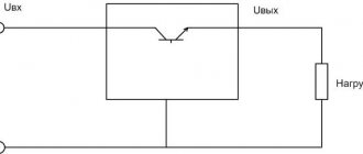
A secondary power source is a device used to convert electrical energy from the primary power supply into electrical energy with the required characteristics and parameters.
Secondary power supplies can be integrated into the overall circuit in the following cases:
there is a need to regulate and stabilize the voltage in a given range; there is a need to prevent voltage drop on the supply wires.
The main tasks of the secondary power supply are:
- Voltage shape transformation. The solution to this problem involves converting direct voltage into alternating voltage or vice versa, generating voltage pulses, etc. At industrial facilities, as a rule, there is a need to convert alternating voltage to direct voltage.
- Ensuring power transmission. The secondary power source must ensure the transmission of the installed power with the least loss and compliance with the required output characteristics.
- Converting the voltage value. Electrical power sources must have the ability to increase and decrease voltage, since quite often several voltages (different values) are needed for the functioning of different networks.
- Stabilization. At the output, the values of electric current, voltage and other parameters must be within a certain range, depending on their purpose.
- Equipment protection. Electrical current and voltage during a malfunction may exceed permissible limits, which will cause electrical equipment failure. In some cases, protection against current flow through the wrong path is also necessary.
- Galvanic isolation of the electrical circuit.
- Adjustment. The need to adjust network parameters may be required if its operating conditions change for normal operation.
- Management. This task consists of turning on/off, adjusting any circuit or the source itself. Control can be carried out remotely or using a special program.
- Control. The solution to this problem is to display parameters at the input and output of the power source, trigger protection, etc.
Are you an expert in this subject area? We invite you to become the author of the Directory Working Conditions
Types of switching power supplies
With galvanic isolation.
High-frequency signals are supplied to a transformer responsible for galvanic isolation of the circuits. Devices of this type have a more compact magnetic core and are characterized by increased efficiency. Most often, the transformer core is made of ferromagnets rather than electrical steels, which also makes it possible to reduce the size of the elements.
Without galvanic isolation.
There is no high-frequency isolation transformer in the pulse power supply circuit. The supply signal is fed to a low-pass filter.
Schematic diagram of a switching power supply
Main elements of switching power supplies:
- network rectifier;
- storage filter tank;
- power transistor;
- generator;
- transistor feedback circuit;
- optocoupler;
- switching power supply;
- output diode rectifier;
- output voltage control circuits;
- filter capacitors;
- chokes designed for diagnostics and voltage correction;
- output connectors.
If the device uses a DC-DC converter, then the first two components become unnecessary. The signal goes directly to the PWM (pulse width modulator). This element is the most complex in the UPS design. Its main functions:
- generation of high frequency pulses;
- control and correction of the frequency sequence taking into account feedback data;
- overload protection.
From the PWM module the signal goes to the key transistors. Their power terminals are loaded onto the primary winding of the high-frequency transformer. In the UPS design, instead of conventional bipolar transistors, MOSFET or IGBT elements are used, which are characterized by minimal voltage drop and speed.
From the secondary winding of the pulse transformer (there may be several such elements in the circuit), voltage is supplied to the output diodes with an increased operating frequency. Most often, Schottky diodes are used in designs.
The function of the output filter is to reduce rectified voltage ripple.
Adjustable width pulse generator circuit
Bipolar symmetrical pulses of adjustable width can be obtained using a pulse generator according to the circuit in Fig. 1. The device can be used in circuits for auto-regulating the output power of switching power supplies. The DD1 chip (K561LE5/K561 LAT) contains a rectangular pulse generator with a duty cycle of 2.
The symmetry of the generated pulses is achieved by adjusting resistor R1. The operating frequency of the generator (44 kHz), if necessary, can be changed by selecting the capacitance of capacitor C1.
Rice. 1. Circuit of a shaper of bipolar symmetrical pulses of adjustable duration.
Voltage comparators are assembled on elements DA1.1, DA1.3 (K561KTZ); on DA1.2, DA1.4 - output keys. Rectangular pulses are supplied to the inputs of comparator switches DA1.1, DA1.3 in antiphase through forming RC diode chains (R3, C2, VD2 and R6, C3, VD5).
The charging of capacitors C2, C3 occurs according to an exponential law through R3 and R5, respectively; discharge - almost instantly through diodes VD2 and VD5. When the voltage on capacitor C2 or C3 reaches the operating threshold of the comparator switches DA1.1 or DA1.3, respectively, they are turned on, and resistors R9 and R10, as well as the control inputs of the keys DA1.2 and DA1.4, are connected to the positive pole of the source nutrition. Since the switches are switched on in antiphase, such switching occurs strictly one by one, with a pause between pulses, which eliminates the possibility of through current flowing through switches DA1.2 and DA1.4 and the converter transistors controlled by them, if a bipolar pulse generator is used in a switching power supply circuit.
Smooth control of the pulse width is carried out by simultaneously applying a starting (initial) voltage to the inputs of the comparators (capacitors C2, C3) from potentiometer R5 through diode-resistive chains VD3, R7 and VD4, R8. The maximum control voltage level (maximum output pulse width) is set by selecting resistor R4. The load resistance can be connected using a bridge circuit - between the connection point of elements DA1.2, DA1.4 and capacitors Ca, Cb. Pulses from the generator can also be supplied to a transistor power amplifier. When using a bipolar pulse generator in a switching power supply circuit, the resistive divider R4, R5 should include a regulatory element - a field-effect transistor, an optocoupler photodiode, etc., which allows, when the load current decreases/increases, to automatically adjust the width of the generated pulse, thereby controlling the output converter power. As an example of the practical implementation of switching power supplies, we provide descriptions and diagrams of some of them.
Areas of application of switching power supplies
Small-sized UPSs based on integrated circuits are used in the design of chargers for electronic gadgets: tablets, phones, e-books. Elements of this type are also in demand in the production of televisions, amplifiers, medical devices, and low-voltage lighting installations.
Select and order power supplies in the catalog. We offer a wide range of models, competitive prices, and provide competent advice on the characteristics of devices. To contact specialists, call +375 (17) 513-99-92
or
+375 (17) 513-99-93
.