Single-phase Electric Motors 220V Connection Diagrams
If the rotor begins to rotate, then the equality of the moments of these forces will be violated, since the sliding of its turns relative to the rotating magnetic fields will become different.
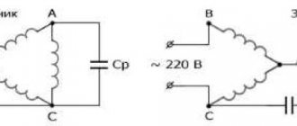
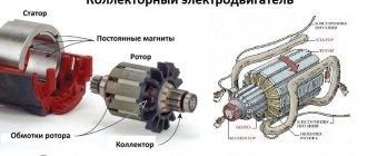
The invention of single-phase commutator motors, capable of withstanding a significant load, producing high torque when starting, adjusting the rotation speed and number of revolutions, has found wide application and use as an electric drive for a washing machine, vacuum cleaner and various power tools that require good power for normal operation. When connecting a three-phase electric motor to network B using a starting capacitor, you need to remember that with such a connection scheme, the motor will not work at full efficiency and will not develop maximum power.
The operating voltage of these capacitors should be 1.5 times higher than the network voltage, that is, for network B we take capacitors with an operating voltage of B and higher. This need is due to the occurrence of a voltage surge when starting and stopping the engine.
Models are available with power from 5 W to 10 kW. However, in favor of efficiency, starting characteristics are sacrificed.
Alternating current flowing through the main winding creates a periodically changing magnetic field. During operation, alternating electric fields flow around the windings: In accordance with this, the so-called starting winding is located on the stationary section of the single-phase motor.
capacitorless starting of a 3-phase motor from 220V
Synchronous motors
It has been known since school days that when magnets are brought close, they attract or repel. The first case occurs at opposite magnetic poles, the second - at like ones. We are talking about permanent magnets and the magnetic field they constantly create.
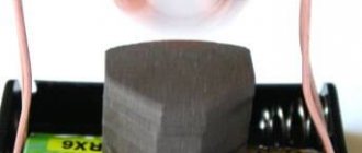
In addition to those described, there are variable magnets. Everyone remembers an example from a physics textbook: the picture shows a magnet in the shape of a horseshoe. Between its poles there is a frame made in the shape of a horseshoe and having half rings. Current was supplied to a horizontally located frame.
Since the magnet repels like poles and attracts unlike poles, an electromagnetic field arises around this frame, which turns it vertically. As a result, it receives a current that is opposite in sign to the first case. The changing polarity rotates the frame and returns it to the horizontal plane.
The operation of a synchronous electric motor is based on this principle.
In a real circuit, current is supplied to the windings of the rotor, which is a frame. The source that creates the electromagnetic field is the windings. The stator performs the functions of a magnet.
It is also made of windings or a set of permanent magnets.
The rotor speed of the electric motor of the described type is the same as the current supplied to the winding terminals, i.e. they work synchronously, which gives the electric motor its name.
Connection diagrams
The winding with a smaller cross-section is the starting one.
This is due to the feature on which the operation of single-phase asynchronous machines is based - a rotating shaft having a rotating magnetic field, being in interaction with a pulsating magnetic field, can operate from one working phase. Afterwards it is turned off by a special device - a centrifugal switch or a start-up relay in refrigerators.
You can measure the resistance with a tester by connecting it to the terminals: at the working winding its value will be less. Inductor.
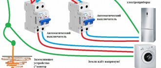
All household appliances, from a juicer to a grinder, have mechanisms of this type. Third-party substances are drawn into the device through cracks in the housing. Single-phase B motors are very popular. Thermal relay The thermal relay operates as follows: when the windings heat up to the limit set on the relay, the relay cuts off the power supply to both phases, thus preventing failure due to overload or other reason, this will prevent a fire from occurring.
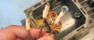
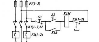
To achieve this technically, the design of the electric motor provides a large number of mechanical parts and electrical circuit components: a stator with a main and additional start winding; squirrel cage rotor; boron with a group of contacts on the panel; capacitors; centrifugal switch and many other elements shown in the above picture. When connecting the device in question, several types of connections are made. That's the whole circuit for switching on a single-phase motor with a bifolar starting winding through a button. Connection diagram for a starting capacitor Since the circuit for short-term connection of a single-phase motor through a capacitor provides a button on a spring, which opens the contacts when released, this makes it possible to save money by making the starting winding wires thinner.
Application of single-phase motors
Therefore, it is important to release the start button in a timely manner.
The result is two differently directed flows with a rotation speed different from the main field. The magnetic field of the main winding maintains rotation for a long time. Options for creating a phase shift The starting coil can operate continuously. There are several such circuits; matching can be achieved using capacitors. In reality, having connected the electric motor, you need to monitor its operation and heating. When connecting the device in question, several types of connections are made. Single-phase commutator motors have the following disadvantages: The complexity of repair work, the impossibility of carrying it out independently.
Use Cases
The working motor from the SM can be used for household needs. Have you decided to tile your yard? Make a homemade vibrating table.
You will need one plate, secured with moving parts to the base. Starting the electric motor from the washing machine will help move the stove. By releasing air from the concrete, you can improve the quality of the tiles, making them stronger and more durable.
You can also make a concrete mixer, but you will need an additional tank. Metal blades in the shape of the letter “P” are installed inside the tank. The drain hole closes. How to connect a washing machine motor to a homemade concrete mixer can be seen in the video:
1. You need to find the Tachometer wires. Usually they have a noticeably smaller cross-section and when “ringed” with a multimeter, they can show resistance or ring with a “chime”. The tachometer is located at the rear (relative to the pulley) of the electric motor, with wires coming out of it.
2. The brushes are located by sequentially “diagning” the wires. The two wires should ring with each other and should also ring with the motor commutator.
3. The winding may have two or three wire leads. It is also located by sequential “ringing” of wires. If you have three terminals (with a middle point), you need to measure their resistance to each other. Two of them should show more resistance, the other end, less resistance. If you choose a winding with more resistance, you will get less revolutions, but more torque. Conversely, a winding with less resistance will give more revolutions, but less torque.
4. Thermocouple wires have two wires and are usually colored white. In our case they will not be used. Not shown in the picture!
Now, after all the wires have been found, you need to randomly connect one wire from the brushes to one of the wires of the selected winding. We connect the two remaining leads (from the brushes and winding) to a 220V network. If you want to change the direction of rotation of the rotor, you need to change the ends of the connection between the wires of the brushes and the windings.
After you have checked the operation of the electric motor from the network, you now need to connect it to the board. To do this, on the back side of the board, under the three terminals on it, there are the letters “AC””M””T”.
“AC” – designates the terminal to which the 220V mains power is connected. "M" - indicates the terminal to which the motor is connected. The same wires that were connected to the network above. “T” is the terminal to which the tachometer wires are connected.
How best to use the board in your system
Since motors from automatic washing machines are high-speed, they are still designed to operate in this range. Since this is related to its cooling and the moment of force on the shaft (torque). Therefore, if you plan to use the engine at low speeds with full torque (at the full power declared by the manufacturer), then you may need to install additional cooling (cooler). Since the airflow of the installed impeller due to low speeds may not be enough. If you touch the electric motor with your hand and cannot hold it for more than 15 seconds, then additional cooling is required.
Since the engine is high-speed, its maximum power is achieved when the board is adjusted from 600 rpm. All revolutions that are lower may not have the maximum torque. Therefore, if your system requires very low speeds (from 1 to 600), you need to use a belt drive consisting of two pulleys (for example, from the same washing machine).
Thus, you will “Kill three birds with one stone”, achieve very low speeds, get even more torque (force on the shaft), and have a smooth intake with speed control.
If you need to connect two motors to the board at the same time, or power any motor with direct current, then you need to use a diode bridge at the output of the board with the further connection described above.
Connecting the motor from an automatic washing machine
Before we talk about connecting the washing machine motor, you need to understand what it is. Perhaps someone has known the wiring diagram for the electric motor of a washing machine for a long time, while others are hearing it for the first time.
An electric engine is a machine powered by electricity that serves as a drive for various mechanisms, i.e. setting them in motion. They produce asynchronous and synchronous units.
Connection
Calculating the values of their capacitances is relatively simple: for the working one 0.75 μF per 1 kW of power, for the starting one - 2.5 times more. Its structure is slightly different from a conventional single-phase asynchronous motor.
A circuit with a working, always-on capacitor works better in nominal mode, but has mediocre starting characteristics. The operating voltage of these capacitors should be 1.5 times higher than the network voltage, that is, for network B we take capacitors with an operating voltage of B and higher.
But despite this, they are widely used in the production of household appliances. These motors have lower efficiency values.
After assembling the electromagnetic starter circuit, you should connect the power section. Its structure is slightly different from a conventional single-phase asynchronous motor. Its power can range from five to ten kilowatts. In addition to the presence of two phases, it is required that one winding be shifted relative to the other by a certain angle.
Operating principle of a commutator motor
Starting scheme: Starting is carried out by a magnetic field, which rotates the moving part of the motor. Next example.
Single-phase asynchronous electric motors Design and principle of operation The power of such a single-phase motor B can, depending on the design, range from 5 W to 10 kW. On which of them there is no difference, the direction of rotation does not depend on it. Look at the photo and you can clearly see that the wire cross-sections are different. When connecting the device in question, several types of connections are made. That is, if the auxiliary winding of a single-phase motor is starting, its connection will occur only during the start-up, and if the auxiliary winding is a capacitor, then its connection will occur through a capacitor, which remains turned on during engine operation.
Electric motor connection options
Most often, connecting an electric motor at 220/380V with an existing capacitor is used, through which the power is reduced. The capacitor contact should be connected to zero, while the other should be connected to the next output of the motor. The result is a device with minimal power.
With increased power, a starting capacitor should be added to the existing circuit. When connected single-phase, it announces the third output.
As for the method of connecting an asynchronous electric motor, it is simply connected with a triangle, as well as a star. Such units have several windings. To change the existing voltage, you cannot do without swapping the outputs that go to the top of the connections.
When connecting such motors, it is important to read the instructions and certificate, since in imported versions you can often find a triangle that is suitable for domestic 220 volts. Such engines, if you are not careful about this issue and are connected with a star, immediately burn out.
With a power reaching more than 3 watts, it is not recommended to connect the motor, as this may cause a short circuit and damage the RCD.
Useful tips Connection diagrams Principles of operation of devices Main concepts Meters from Energomer Precautions Incandescent lamps Video instructions for the master Testing with a multimeter
How to connect a 220V asynchronous motor
Since the supply voltages for different consumers may differ from each other, there is a need to reconnect electrical equipment. Making the connection of a 220-volt asynchronous motor safe for further operation of the equipment is quite simple if you follow the proposed instructions.
In fact, this is not an impossible task. In short, all we need is to connect the windings correctly. There are two main types of asynchronous motors: three-phase with a star-delta winding, and motors with a starting winding (single-phase). The latter are used, for example, in Soviet-designed washing machines. Their model is AVE-071-4C. Let's look at each option in turn.
The AC induction motor has a very simple design compared to other types of electrical machines. It is quite reliable, which explains its popularity. Three-phase models are connected to an alternating voltage network with a star or delta. Such electric motors also differ in operating voltage: 220–380 V, 380–660 V, 127–220 V.
Such electric motors are used in production, since three-phase voltage is most often used there. And in some cases it happens that instead of 380 V there is three-phase 220. How to connect them to the network so as not to burn the windings?
How to select capacitors?
If you are planning to connect an electric motor, then the choice of capacitor is carried out according to the following principles:
Table: determination of capacitor capacity
If the power you need is not in the table, you can use the calculation formulas:
Serb = (2800*I)/U - to turn on a three-phase motor with a star
Crab = (4800*I)/U - to turn on a three-phase motor with a triangle
where I is the amount of current flowing through the windings of the electric motor, and U is the network voltage. To find out the capacity of the starting capacitor for connecting a three-phase unit, you need to multiply the resulting working value by two.
Switching to the desired voltage
First we need to make sure that our engine has the necessary parameters. They are written on a tag attached to his side. It should indicate that one of the parameters is 220V. Next, let's look at the connection of the windings. It is worth remembering this pattern of the circuit: star - for lower voltage, triangle - for higher voltage. What does this mean?
Voltage increase
Let's say the tag says: Δ/Ỵ220/380. This means that we need a delta connection, since most often the default connection is 380 volts. How to do it? If the electric motor in the burner has a terminal box, then it is not difficult. There are jumpers there, and all you need to do is switch them to the desired position.
In this situation this does not cause any difficulties. The main thing to remember is that there is a beginning and an end to the coils. For example, let’s take as a starting point the ends that were brought out into the boron of the electric motor. This means that what is soldered is the ends. Now it’s important not to get confused.
We connect like this: we connect the beginning of one coil to the end of the other, and so on.
As you can see, the scheme is simple. Now the engine, which was connected for 380, can be connected to a 220 volt network.
Voltage reduction
Let's say the tag says: Δ/Ỵ 127/220. This means a star connection is required. Again, if there is a terminal box, then everything is fine. What if not, and our electric motor is turned on in a triangle? And if the ends are not signed, then how to connect them correctly? After all, here it is also important to know where the coil winding begins and where the end is. There are some ways to solve this problem.
First, let's move all six ends apart and use an ohmmeter to find the stator coils themselves.
Let's take adhesive tape, duct tape, whatever else we have, and mark them. It will come in handy now, and maybe someday in the future.
We take a regular battery and connect it to ends a1-a2. We connect an ohmmeter to the other two ends (c1-c2).
At the moment the contact with the battery is broken, the arrow of the device will swing to one side. Let's remember where it swung and turn on the device to ends c1-c2, without changing the polarity of the battery. Let's do it all over again.
If the arrow deviates in the other direction, then we swap the wires: we mark c1 as c2, and c2 as c1. The point is that the deviation is the same.
Now we connect the battery, observing polarity, to ends c1-c2, and the ohmmeter to a1-a2.
We ensure that the needle deflection on any reel is the same. Let's double check again. Now one bundle of wires (for example, with the number 1) will be the beginning, and the other will be the end.
We take three ends, for example, a2, b2, c2, and connect them together and isolate them. This will be a star connection. As an option, we can output them directly to the terminal block and label them. We paste the connection diagram onto the lid (or draw it with a marker).
Reconnection from 380V to 220
To connect a three-phase motor to 220 volts, it is important to know that it has six terminals that fully correspond to several windings. Using a wire tester, a ring is made to search for the coil. The ends are combined in pairs to form triangles.
First of all, several ends of the network wire are connected to several ends of the resulting triangle. The unused end is attached to the capacitor, while its free wire is also connected to the end of the coils, as well as the network wires.
The choice of option determines exactly where the motor will rotate. Having completed the necessary steps, the motor is started after supplying 220 volts to it.
If a hum is observed during the connection process, but the engine does not spin, a capacitor must be installed, which causes the motor to spin during the startup process, as in the photo of connecting an electric motor on the website.
Resistance is measured using a tester. If it is not available, you can use a battery or a light bulb designed for a flashlight: certain wires are connected directly to the circuit with the lamp.
If the ends of the winding are found, the light bulb lights up. It is much more problematic to determine the ends, as well as the beginning of the windings. In this case, a voltmeter is needed.
When the battery and wire break, it is important to look to see if the needle deviates. Similar actions must be carried out with other windings in order to change when polarity is achieved. The needle deflects to the original measurement.
How to connect an electric motor from 380 to 220: methods and diagrams
Do not turn on the electric motor without load. Since it is not designed for such a mode, the electric machine will quickly fail. Minimize idling as much as possible.
Expert opinion
It-Technology, Electrical power and electronics specialist
Ask questions to the “Specialist for modernization of energy generation systems”
Connecting the electric motor The starting motor is introduced briefly, the additional capacitance allows you to increase the voltage shift in the corresponding winding and create greater force. Ask, I'm in touch!
Single phase
Now let's talk about another type of asynchronous electric motors.
These are single phase AC capacitor machines. They have two windings, of which, after starting, only one of them works. Such engines have their own characteristics. Let's look at them using the example of the ABE-071-4C model. In another way, they are also called split-phase asynchronous motors. They have another auxiliary winding wound on the stator, offset relative to the main one. Starting is carried out using a phase-shifting capacitor.
Diagram of a single-phase asynchronous motor
From the diagram it can be seen that AVE electric machines differ from their three-phase counterparts, as well as from single-phase collector units.
Always carefully read what is written on the tag! The fact that three wires are output does not mean at all that it is for a 380 V connection. Just burn the good stuff!
Getting started
The first thing to do is determine where the middle of the coils is, that is, the junction. If our asynchronous device is in good condition, then this will be easier to do - by the color of the wires. You can look at the picture:
If everything is displayed like this, then there will be no problems. But most often you have to deal with units removed from the washing machine unknown when, and unknown by whom. Here, of course, it will be more difficult.
It is worth trying to call the ends using an ohmmeter. The maximum resistance is two coils connected in series. Let's mark them. Next, we look at the values that the device shows. The starting coil has more resistance than the working coil.
Now let's take the capacitor. In general, they are different on different electrical machines, but for ABE it is 6 uF, 400 volts.
If this is definitely not the case, you can take one with similar parameters, but with a voltage not lower than 350 V!
Let's pay attention: the button in the figure serves to start the ABE asynchronous electric motor when it is already connected to the 220 network! In other words, there must be two switches: one general, the other a starting one, which, after being released, would turn itself off. Otherwise, you will burn the device.
If reverse is needed, then it is done according to this scheme:
If everything is done correctly, then it will work. However, there is one catch. Not all ends can be drawn into boron. Then there will be difficulties with reverse. Unless you disassemble and take them out yourself.
Here are some points on how to connect asynchronous electrical machines to a 220 volt network. The schemes are simple, and with some effort it is quite possible to do it all with your own hands.
Source
Asynchronous or collector: how to distinguish
In general, you can distinguish the type of engine by a plate - a nameplate - on which its data and type are written. But this is only if it has not been repaired. After all, anything can be under the casing. So if you are not sure, it is better to determine the type yourself.
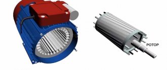
This is what a new single-phase capacitor motor looks like
How do collector motors work?
You can distinguish between asynchronous and commutator motors by their structure. The collectors must have brushes. They are located near the collector. Another mandatory attribute of this type of engine is the presence of a copper drum, divided into sections.
Such motors are produced only as single-phase ones; they are often installed in household appliances, as they allow one to obtain a large number of revolutions at the start and after acceleration. They are also convenient because they easily allow you to change the direction of rotation - you just need to change the polarity. It is also easy to organize a change in the rotation speed by changing the amplitude of the supply voltage or its cutoff angle. That is why such engines are used in most household and construction equipment.
Commutator motor structure
The disadvantages of commutator motors are high operating noise at high speeds. Remember a drill, an angle grinder, a vacuum cleaner, a washing machine, etc. The noise during their operation is decent. At low speeds, commutator motors are not so noisy (washing machine), but not all tools operate in this mode.
The second unpleasant point is that the presence of brushes and constant friction leads to the need for regular maintenance. If the current collector is not cleaned, contamination with graphite (from brushes being worn out) can cause adjacent sections in the drum to become connected and the motor simply stops working.
Asynchronous
An asynchronous motor has a stator and a rotor, and can be single or three-phase. In this article we consider connecting single-phase motors, so we will only talk about them.
Asynchronous motors are characterized by a low noise level during operation, therefore they are installed in equipment whose operating noise is critical. These are air conditioners, split systems, refrigerators.
Structure of an asynchronous motor
There are two types of single-phase asynchronous motors - bifilar (with a starting winding) and capacitor. The whole difference is that in bifilar single-phase motors the starting winding works only until the motor accelerates. Afterwards it is turned off by a special device - a centrifugal switch or a start-up relay (in refrigerators). This is necessary, since after overclocking it only reduces efficiency.
Connection diagrams for single-phase asynchronous motors
With starting winding
To connect a motor with a starting winding, you will need a button in which one of the contacts opens after switching on. These opening contacts will need to be connected to the starting winding. In stores there is such a button - this is PNDS. Its middle contact closes for the holding time, and the two outer ones remain in a closed state.
Appearance of the PNVS button and the state of the contacts after the “start” button is released"
First, using measurements, we determine which winding is working and which is starting. Typically the output from the motor has three or four wires.
Consider the option with three wires. In this case, the two windings are already combined, that is, one of the wires is common. We take a tester and measure the resistance between all three pairs. The working one has the lowest resistance, the average value is the starting winding, and the highest is the common output (the resistance of two windings connected in series is measured).
If there are four pins, they ring in pairs. Find two pairs. The one with less resistance is the working one, the one with more resistance is the starting one. After this, we connect one wire from the starting and working windings, and bring out the common wire. A total of three wires remain (as in the first option):
We work further with these three wires - we use them to connect a single-phase motor.
- Connecting a single-phase motor with a starting winding via the PNVS button
connecting a single-phase motor
We connect all three wires to the button. It also has three contacts. Be sure to place the starting wire on the middle contact (which closes only during the start), the other two - on the outermost (arbitrary). We connect a power cable (from 220 V) to the extreme input contacts of the PVNS, connect the middle contact with a jumper to the working one (note! not to the common one). That's the whole circuit for switching on a single-phase motor with a starting winding (bifilar) through a button.
Condenser
When connecting a single-phase capacitor motor, there are options: there are three connection diagrams and all with capacitors. Without them, the engine hums, but does not start (if you connect it according to the diagram described above).
Connection diagrams for a single-phase capacitor motor
The first circuit - with a capacitor in the power supply circuit of the starting winding - starts well, but during operation the power it produces is far from rated, but much lower. The connection circuit with a capacitor in the connection circuit of the working winding gives the opposite effect: not very good performance at start-up, but good performance. Accordingly, the first circuit is used in devices with heavy starting (concrete mixers, for example), and with a working condenser - if good performance characteristics are needed.
Circuit with two capacitors
There is a third option for connecting a single-phase motor (asynchronous) - install both capacitors. It turns out something between the options described above. This scheme is implemented most often. It is in the picture above in the middle or in the photo below in more detail. When organizing this circuit, you also need a PNVS type button, which will connect the capacitor only during the start time, until the motor “accelerates”. Then two windings will remain connected, with the auxiliary winding through a capacitor.
Connecting a single-phase motor: circuit with two capacitors - working and starting
When implementing other circuits - with one capacitor - you will need a regular button, machine or toggle switch. Everything connects there simply.
Selection of capacitors
There is a rather complex formula by which you can calculate the required capacity accurately, but it is quite possible to get by with recommendations that are derived from many experiments:
The operating voltage of these capacitors should be 1.5 times higher than the network voltage, that is, for a 220 volt network we take capacitors with an operating voltage of 330 V and higher. To make starting easier, look for a special capacitor for the starting circuit. They have the words Start or Starting in their markings, but you can also use regular ones.