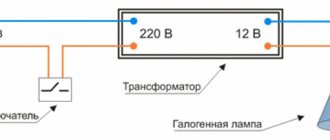
Is it possible to connect two wires into one circuit breaker?
There is often a situation where you need to connect two wires into one machine.
Before doing this, you should know the features of such a connection, and also correctly calculate the load resulting from the connection, whether it exceeds the rating of the circuit breaker. You also need to know the correct way to connect both wires to the machine contact, since an incorrect connection will either lead to the contact burning out, or the machine terminal will not make contact with the wire. Now about everything in detail.
Possible problems with such a connection
We list the main problems of connecting two wires to one machine :
1) Overstating the machine - the wiring will burn out
Each machine has its own nominal characteristics. Each wire also has its own characteristics, depending on the cross-section of the wire and its type. In electrical applications, copper wires are the most popular.
In the case when the wire cross-section is designed, for example, for a current of 21 amperes (for a wire with a cross-section of 1.5 mm2), the machine must be installed with a rating of no more than 16 amperes. Considering that with an overload of 45%, any circuit breaker may not turn off for 1 hour (1.45 * 16 = 23.2 A), the wire will have a certain safety margin.
The main purpose of the machine is to protect electrical wiring and electrical appliances connected to it from high currents that occur during a short circuit and overload.
It happens that a circuit breaker is often knocked out, while many simply replace it with a circuit breaker of a higher rating. But at the same time, the installed machine accordingly passes a current whose strength exceeds the maximum possible for normal operation of the wiring. As a result, such wiring burns out, melts, and can even short out due to insulation failure.
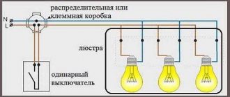
When connecting two wires to one machine, follow a very simple rule:
| Both wires must be of the same cross-section and correspond to the rating of the machine! |
For example, a 16 amp machine is available. For proper connection, we take two NYM type cables with a cross section of 3×2.5. The maximum permissible continuous current value for such a cable is 25 A if the cable is hanging in the air, and 38 A if it lies in the ground. Since our cable does not lie in the ground, so as not to test it under maximum loads, a 16 Ampere circuit breaker is the ideal solution for such a cable, and in our case, for two wires.
2) Poor contact at the terminal
When connecting two wires to one machine, a problem arises: how to ensure tight contact between the machine terminal and both ends of the wire.
It has already been written above that the wires must be of the same cross-section. Why? When connecting wires of different cross-sections to the circuit breaker, when you tighten the terminal, one of the wires will not have good, tight contact with the terminal due to the larger wire .
Many “Kulibins” will immediately say “twist two wires of different sections into a twist and you will be happy.” There are statistics for this that show that twisting is the most common cause of malfunction in electrical wiring. Due to poor fastening, the twist will constantly fall out, or, no, touching the terminal of the machine, it will short out.
Two wires of the same cross-section will fit perfectly into the terminal of the machine without twisting. If you need to connect wires of different sections or more than two in number, then it is better to use special cross modules or buses for these purposes.
To connect multi-core wires, there is a decent way out of this situation - NSHVI lugs (insulated pin sleeve lug). These are special connectors that are designed to connect two wires. They have a cone-shaped input and a metal contact that is directly inserted into the terminal of the machine.
NShVI tips are divided into two types: NShVI and NShVI-2. NShVI are designed for terminating the cores of one wire, and NShVI-2 is for terminating two multi-core wires with one sleeve with the possibility of connecting them later to one terminal.
The use of such tips will ensure, firstly, ideal contact of the electrical wiring with the terminal of the machine, and secondly, it will give an aesthetic appearance to your panel. All connections will be neat and reliable without any twists, and two wires will be connected perfectly into one circuit breaker.
Connecting mono-core and multi-core in the terminal of the machine
Friends, especially for comment No. 1 under this article, I decided to consider another way to connect two wires in a machine, and the wires are different in design. We are talking about connecting single-core (monolithic) and stranded wires to the terminal of the circuit breaker.
The NShVI tip will help us with this. We take two wires, remove the insulation from them and crimp them with a double tip. In my example, both monolithic and stranded wires with a cross-section of 2.5 mm2 are crimped NShVI(2)-2.5.
The advantage of this connection is that the wall of the tip itself is thin and under the action of the screw force the sleeve will compress, thereby improving the connection of the wires.
PS There is no need to twist the wires when crimping. Moreover, you don’t need to just stick such a twist under the terminal. When tightening, half of the strands will simply be damaged, and this will lead to poor contact and GOOD heating in the future.
| In general, it is best in such cases to buy another circuit breaker, add it to the panel and connect each cable to its own circuit breaker. It will be BETTER and MORE RELIABLE. But if suddenly..., suddenly... this is not possible, then we use the methods indicated in this article. |
3) The connected load exceeds the power of the machine
It happens that several devices are hung on one machine, the power consumption of which exceeds its rated current, which is why the latter constantly knocks out immediately when the electrical devices are turned on at the same time.
I’ll tell you a situation in which I myself was directly involved. One day I was invited to repair the wiring (at least that’s how they phrased the request over the phone). In the end I came across the following:
- 1. Small gym with two boilers
- 2. 16 amp machine
- 3. Each boiler has a separate cable line with a separate socket
- 4. Both wires are connected to the same terminal of the circuit breaker.
When both boilers were turned on at the same time, the machine immediately went off. Now we look at the power of each boiler. It turned out to be the same: 3.5 kW for each. The cable type for each boiler is a three-core cable VVG-nG-Ls, cross-section - 2.5 mm². Now we count:
- – Current load for one boiler: 3.5 kW × 1000 = 3500/220 volts = 15.9 Amperes.
- – Both machines consume a total of 31.8 Amps.
As you can see, the load on both boilers exceeded the rating of the 16 Amp circuit breaker twice. In this case, the cable used allows a load of up to 27 A. Accordingly, the wire to the boiler is normal, we leave it. Now we remove the 16 A circuit breaker and install two 20 A circuit breakers.
We connect each boiler to a separate machine. It would be possible to take two 16 A machines, but then the rating of the machine would be one tenth higher than the boiler load (16-15.9=0.1). In this case, constant operation of the thermal protection is POSSIBLE.
Connecting three wires of different sections using screw terminals
Three wires of different thicknesses can be reliably connected to each other using special ZVI screw clamps. The clamps have a very convenient design and allow you to create contact between cables that have different cross-sections. The strength of the connection is achieved by using separate screws for each clamp.
You need to select ZVI clamps taking into account the cross-section of the wires that will be connected, as well as their current load. For reliable contact, it is recommended to connect three wires of adjacent sections. Let us conventionally designate the cross-section of the connected conductors as SPP, and the permissible long-term current as DDT. Below are the parameters of clamps and wires:
- ZVI-3 – SPP 1 – 2.5; DDT – 3;
- ZVI-5 – SPP 1.5 – 4; DDT – 5;
- ZVI-10 – SPP 2.5 – 6; DDT - 10;
- ZVI-15 – SPP 4 – 10; DDT - 15;
- ZVI-20 – SPP 4 – 10; DDT - 20;
- ZVI-30 – SPP 6 – 16; DDT - 30;
- ZVI-60 – SPP 6 – 16; DDT - 60;
- ZVI-80 – SPP 10 – 25; DDT - 80;
- ZVI-100 – SPP 10 – 25; DDT - 100;
- ZVI-150 – SPP 16 – 35; DDT - 150.
With the right choice of screw clamp, you can create a truly reliable connection that will ensure uninterrupted operation of the electrical network.
Legal way to branch a wire in a machine terminal
Dear Pikabushniki, tell me, is there a legal way to branch the wire into the terminal of the machine?
There is a small outdoor cabinet like IEK SHU-3/1-0 U1 IP54 (MKM51-N-03-54). It contains a three-phase meter, after which there is a three-phase 32A circuit breaker. A VVGng 4x6 comes out of the machine and goes to the panel inside the house. Task: to hang another cabinet under it, in which there will be a three-phase 25A circuit breaker, which should protect the cable that supplies power to the workshop (and in the same cabinet, organize a couple of sockets for connecting outdoor equipment like a lawn mower). There is a small problem: there is not enough free space in the cabinet with the meter.
How can you connect a wire from the house and a wire going to the lower panel in parallel into a 32A circuit breaker? It is dangerous to clamp two wires with a breaker terminal. Crimp single-core and multi-core with a sleeve - they will not fit under the terminal. Replace the cabinet - damage to the seals on the meter.
Is there a way out with minimal losses?
No duplicates found
1st method: lug for two wires type NGI2
2nd method: branch compression series U 13x type “walnut”
3rd method: bus adapter like this
Wow, there are so many options. I’ve never seen anything like this on the shelves in our steppe. We need to look into the ETM.
I had the same problem: I installed a powerful homemade terminal block made of 20 PCB with embedded M 8 bolts and cap nuts and washers, installed it between the input machine, and the machines that went to the machines, connected the power wires by twisting, made a ring out of them, tinned them in a crucible with molten tin, and connected the terminal block, clamped the union nut with a socket wrench, tightly placing the washers, it turned out fine and closed the contacts on top with a strip of thin textolite with screws, I think with this method there is no better way to check the contact after a year, I didn’t even have to press it, the main thing is to select the correct wire cross-section, who doesn’t know the table available on the Internet
oh that's it. I was told dangerous means dangerous. You do not love me
There are people who are afraid of everything. Vag, 2 lived in the machine, B20 for 2.5 mm2))
What are you talking about) 2.5 holds 27-32 A, up to 70 degrees. B20 and c20 are kept at 20×1.45 = 29A for no more than an hour. Which is more than acceptable. All the leftist excuses about 16A sockets are stupid nonsense, if only because of the same coefficients
This is for you. The factory provides for long-term operation at this temperature.
You can’t protect yourself from all the idiots, the electrician automatically protects the cable, and that’s all, the EUI can be installed as shit by default, and it will melt even at 10A, so what? Maybe the extension cord with its 0.75 pass should also be planned to be protected in advance?
Yes, and the coefficient of 1.13 and 1.45 has not been canceled
And the machine at 16 holds 23.2A for an entire hour.
Show me at least one store extension cord with at least 1.5
Honestly, bravo. It’s really the first time I see how old he is?) Of course, for the purity of the experiment, look at the cross-section of the veins. otherwise I cut the power supply wires, all 3g0.75. but they differ in cross section by 2 times exactly. but not much in terms of overall thickness)
Keep him safe! It will be an exhibit!)))
It doesn't count, I'm all like that. only with normal sockets)
Because the denominations are large. In a 10-16A machine, I would do this without hesitation.
So the terminal, for a second, is designed for this, and with a reserve. This is its standard connection option. You can have one conductor, you can have two.
And here in more detail please)
And calmly clamp the same section here, and don’t worry. Everything will work perfectly, there is no need to create an extra garden, it will be worse. But if you really want to, you run a cable from the existing cabinet into a new shield, and there is either a cross-connect, or as they wrote below - ABB S203
a simple and legal way - you take a wire, stick it into the switchboard, pull it to another switchboard and stick it into it. Voila, it's simple.
The simplest and most ideal way to branch the input in your case to the meter ambassador is to use distribution blocks from ABB (I attach a photo). Run the input wire from the machine into the block, and from it into both machines, that is, the wire after the PU (metering device) immediately goes to the distribution blocks, and from them goes to the machines. A huge advantage of these blocks is the use of hex screws, which can be tightened much more tightly than with a regular screwdriver (the same terminal in a machine or cross-module). The downside is the price, since you will need 4 pieces (for each phase and for 0), as far as I remember there are also three-phase options. Accordingly, the indicated blocks in the pictures pull a load of 125 A. Perhaps there is something newer, but by installing these blocks you will not worry about the contacts. All the best to you and remember, saving on wiring is a bad idea, because even steel panels burn out.
They have shitty plastic; when you snap them onto the rail, the lock on three out of four will break. If only you fasten it to the back wall with self-tapping screws by the eyes.
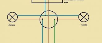
How to connect several wires to one Machine in the Panel
I apologize for the question - in electrics there is a “kettle”.
I'm going to replace the wiring in a 3-room apartment. I’m used to doing everything well (I am a system administrator myself and am familiar in practice with Structured Cabling Systems, but for computer networks, not for electrical work), but for myself it’s very good.
Now I'm drawing up a diagram of the electrical wiring in the apartment. After reading information on the Internet, I determined that the best wiring option is “star”. But then the question is:
- There will be a bunch of wires coming to the apartment panel, how can they then be combined into groups and connected to automatic machines and RCDs?
I couldn't find such information anywhere.
Thanks in advance for your answers.
Two monocores of the same cross-section can simply be clamped together.
familiar in practice with Structured Cabling Systems
If the budget allows and there is an unmotivated desire to do it “in an adult way,” then you need to use terminal blocks. But is it needed in a household panel?
the best wiring option is “star”
Not every outlet has a beam, I hope? In order not to get confused with these dozens of wires, you can make not one shield, but a pair (or even three), distributing the groups according to territorial basis (saving copper) or functional (saving only nerve cells).
You can combine using insulated busbars with separate bolts for each wire - see the black busbars under the group machines in the photo. Photo taken from the page of the respected master Yurka mastercity.ru/vforum/showthread.php?t=27154
DmitryM wrote: After reading the information on the Internet, I determined that the best wiring option is “star”. But then the question is:
- There will be a bunch of wires coming to the apartment panel, how can they then be combined into groups and connected to automatic machines and RCDs?
Greetings, colleague. VTB has already answered you, it’s difficult to add anything here, just use common sense and group the loads so that a bunch the size of a broom does not form on the central shield. So group, combine and centralize, like we do in the computer. We do networks (we connect small switches to central ones.)
Yeah, the “star” is within the room, 1 cable goes from the room to the panel.
Rough analogies: the shield is a stand, positions on the slats are units; terminal blocks (bottom rail in the photo) - patch panel; various types of buses and distributors - passive hubs; line sections - category.
DmitryM wrote: How to connect several wires to one Automatic in the Shield
Just like connecting several workstations using one UTP connection, it is possible, but this is a perversion.
VTB! wrote: distributors are passive hubs;
Why swear in public?
evgenygrig wrote: Yeah, the “star” is within the room, 1 cable goes from the room to the panel.
But with this configuration, it is necessary to install a junction box in each room, and this is not desirable.
VTB! wrote: Rough analogies: the shield is a stand, positions on the slats are units; terminal blocks (bottom rail in the photo) - patch panel; various types of buses and distributors - passive hubs; line sections - category.
Thanks for the analogies. That's pretty much how I imagined it myself.
evgenygrig wrote: You can combine using insulated busbars with separate bolts for each wire
Thank you very much for the photo. It became more clear.
However, this will require a larger shield.
We will make a draft of the scheme. Then it will be more clear how to wire it all up and how many wires will go to the panel.
DmitryM wrote: junction box in every room
Optionally, deep installation boxes - and the task of distribution behind the socket or switch mechanism becomes accessible not only to Akopyan and avmal. The overhead light can be made into a pure star (shield-3*1.5-switch-4-1.5-lamp). It is convenient to route lightly loaded sockets not across rooms, but along walls - a common line on both sides of the wall. And if there is an electrical baseboard on one side of the wall (or both), then adding sockets (if necessary) becomes an elementary task.
this will require a larger shield
It is usually more convenient to install an additional shield in the area of the kitchen and bathrooms - powerful and/or leak-prone consumers are mainly there.
Dear, to reduce the number of wires entering the panel, junction boxes are installed in the premises, or a cable is attached from socket to socket with a cable, as a rule, the socket network and the lighting network must be connected from separate machines, and the electricity is also powered from a separate machine. stove and washing machine. The recommended wire cross-section for laying a socket network is 2.5 sq. mm, and a lighting network is 1.5 sq. mm.
DmitryM wrote: But with such a configuration, it is necessary to install a junction box in each room, and this is not desirable.
Within one room, lead everything to a small panel in this room, and in the panel itself you will do the cross-connection and installation. and there are no boxes, and even suddenly the need arises, you never know, you open the shield and everything is in plain sight, nothing is walled up. In the living room I made 6 sockets (3 groups), 4 sconces (1 group) around the perimeter and 2 chandeliers (1 group), of course, pulling all this with grooves and cables right up to the apartment corridor (where I have the main panel) would have been a bit expensive, but it costs a small panel for 6 seats, and that's it. The electrician on Vaga installed the light on the sconce inside the switchboard there. And even my wife, after installing such a charm, didn’t mind at all
Source: www.mastergrad.com
How many sockets can be connected to one 2.5 wire?
The fact that electrical wiring for sockets in apartments or houses should be done with a VVGng-LS cable with a core cross-section of 2.5 mm2. is known to many, but besides this, other questions often arise; one of the most common ones asked to me is “ How many sockets can you connect to one 2.5 wire?” "
You can hang almost as many electrical outlets on such a cable as you want, and this is no joke. This is because the sockets themselves do not consume electricity and are essentially the same conductor as an electrical cable, therefore they themselves do not have any significant impact on the network.
Do-it-yourself electrical wiring and creating contacts using terminals
Universal clamp terminals appeared on the market relatively recently, but almost immediately began to be in serious demand not only among specialists, but also among potential clients who prefer to carry out all electrical work at home themselves.
Using self-clamping terminals, you can create strong and reliable contacts between several wires ( three or more ). The main advantage of such terminal blocks is their almost unlimited functionality - they can be used to connect wires whose sizes vary significantly.
The design of the terminals provides for the presence of holes into which pre-stripped conductors are inserted. For example, you can insert a wire with a cross-section of 1.5 mm into one hole, a wire with a diameter of 4 mm into another, a wire with a diameter of 4 mm into the third, and so on. And after connecting them, the contact will be quite strong and reliable.
There are several other ways to connect three or more wires of different diameters, but they are used quite rarely due to the complexity and duration of the process itself. If you want to use one of them, first consult with a specialist who is competent in this area.
Source: remont.youdo.com
Methods for connecting machines in a distribution panel
In distribution cabinets and lighting panels, several similar circuit breakers, automatic circuit breakers or RCDs (residual current devices) are often installed on one DIN rail.
In these cases, power is supplied to the switching devices via the main line (loop). There are two ways to connect circuit breakers to each other.
The machines can be connected using wire jumpers or using connecting bars (combs) produced by industry.
Jumper wires
Electricians usually make jumper wires themselves. Any single-core insulated wire of suitable cross-section is suitable for making jumpers.
It is recommended to use single-wire wire PV-1 or multi-wire (flexible) wire PV-3 in vinyl insulation.
The process of making jumpers is simple. First, the length of the conductor is measured and the required number of wire segments is cut. The wires are stripped at both ends.
The length of the bare part of the wire should be 12mm. Then the wire is bent, giving the jumper the desired shape. If a flexible wire is used, lugs are pressed onto the bare ends using press pliers.
An example of connecting machines using jumpers.
The cross-section of the wire for making jumpers must be selected based on the sum of the rated currents of all circuit breakers connected to the first circuit breaker in the loop.
To ensure high-quality contact, it is desirable that the ends of the jumpers connected to one terminal of the machine have the same cross-section.
Often electricians make jumpers between machines from one continuous wire. The appearance of such a jumper attached to the machines is shown in the figure below.
Connecting machines using jumpers has its advantages and disadvantages.
The disadvantages of this connection method include:
- High complexity of manufacturing jumpers. This is especially noticeable with large volumes of electrical installation work.
- If the DIN rails are located close to each other in the panel, the jumpers may interfere with the connection of conductors to the circuit breakers of the top row.
The advantages of using jumpers include low manufacturing costs. If the jumpers are made of unbreakable wire, then it is possible to replace a failed circuit breaker without turning off other circuit breakers.
To do this, disconnect the jumpers from the upper terminals of the machine, put pieces of insulating tube on them, remove the faulty device from the DIN rail and install a new one. Then connect the power wires.
Using busbars
The industry offers two types of combs for connecting modular switching devices. In one type of comb bus, the contacts are made in the form of pins. Another type has fork-shaped contacts.
The combs consist of conductive bars (usually copper) with contacts and a plastic insulating body. The distance between the contacts is equal to the width of one module and is 18 mm. Connecting busbars can have from 1 to 4 poles.
Each pole fits into a separate groove in the housing and is reliably isolated from other conductive busbars. Using a comb bus, you can connect both single-pole circuit breakers and three-phase RCDs.
Connection busbars are available with 12, 24, 36 or 48 modules. The tires can be cut to obtain the required number of modules. For cutting, you can use any suitable tool, such as a hacksaw.
The following technical characteristics are marked on the tire casings:
- cross-section of conductive busbars.
The pin connection bars are suitable for all types of modular switching devices. To use buses with fork contacts, machines must have special terminals.
The use of combs requires greater material costs than the use of wire jumpers. However, the use of connecting busbars significantly reduces the installation time.
In addition, installation performed using combs looks more aesthetically pleasing. There is more space in cabinets and panels.
The disadvantages of using connecting buses include the impossibility of replacing faulty circuit breakers or RCDs without disconnecting adjacent switching devices.
To summarize, we can say that it is better to use jumpers when there is a small number of modular devices on the rail. In the case of a large installation volume, it is advisable to use connecting bars.
Machine connection diagrams
Installing and correctly connecting the machine in the distribution cabinet is not a problem. Even an ordinary person can cope with this, who only encounters electricity when they insert a plug from a household appliance into an outlet or turn on the lighting. But the question of how to properly connect the machine is still often asked by ordinary people. The thing is that even among electricians there are disputes about connection methods. That is, connect the power wire to the circuit breaker from above or below.
Enter from above or below
A very important question that worries both many electricians and just home craftsmen: how to connect the machine, from above or from below? To answer this, you will have to refer to the regulatory documentation, namely, the Rules for the Construction of Electrical Installations.
Paragraph 3.1.6 states that the machine should be connected to the electrical network from the side of the device on which the fixed contact is located. This means that the voltage in a single-phase or three-phase network must be on the side of the switch that does not break the electrical circuit. Paragraph 3.1.6 applies to many types of switching equipment. This can be not only a single-contact, but also a two-pole or three-phase circuit breaker, as well as a differential package or RCD.
You can find out the location of this contact only by disassembling the bag, which is not very convenient every time you replace it in the apartment. But the design of all machines is almost the same, so you should find out where the fixed contact is located on only one switch. And it is located on top, so the connection of a single-pole or two-pole circuit breaker must also be done from above.
If you happen to have a packet from an unknown manufacturer in your hands, then just look at its body, or more precisely, the front panel. In this place, most often all the necessary information is placed on the machine, such as the model, accuracy class, and connection diagram of the circuit breaker with the exact location of the moving and fixed contacts.
Conclusion: the connection of the circuit breaker to the electrical network must be done from above. This is what the regulatory documents say, which help avoid unnecessary confusion.
But if you look from the technical side: is the difference in connecting the power cable significant? Answer: no, it does not matter at all from which side the operating voltage is supplied to the package. The device will work properly both with a connection from above and from below.
Machine device
To move on to the machine’s connection diagrams, you must first understand its design. And since we are interested in connecting wires to the lower or upper contacts of the device, we must understand that both contacts (moving and fixed) are made of different metal alloys.
When it comes to the AC network, when switching the machine, its contacts burn out evenly, and there is no difference where the wires are connected. If the machine is located in a circuit with direct current, then the choice of connection contact is an important component of the correct and long-term operation of the device itself. At high current levels, metals are transferred from one contact to another, so in such networks the supply wires must be connected only from above, that is, through a fixed contact.
Now let's move directly to the machine itself. To help you understand what is inside this device, we recommend that you familiarize yourself with the picture below.
The two main elements that perform the protective functions of the machine are electromagnetic and thermal releases.
Electromagnetic release
This element is a protective element, which is triggered if a short circuit appears in the electrical circuit where the machine itself was installed. It is at this moment that huge currents appear in the circuit (almost thousands of times higher than the rated current value). To prevent the wiring and household appliances plugged into the sockets from burning out, the release instantly turns off the supply network. The shutdown time is milliseconds. By the way, there is a certain marking on time-current characteristics. It is designated by letters of the Latin alphabet and applied to the body of the circuit breaker itself. In everyday life, types “A”, “B”, and “C” are more often used.
The design of the electromagnetic release itself is a core (solenoid) around which the coils of the spring are located. The solenoid is connected directly to the moving contact of the machine. But the spring is connected in series with the power contacts and the thermal release. The rated current is too small for the magnetic flux created inside the coil to retract the core and thereby open the contacts. As soon as a short circuit occurs in the network, that is, a current of enormous magnitude appears, large magnetic fluxes arise inside the coil (spring), the spring compresses and draws in the core, which in turn immediately opens the power contacts. This means that the network will be de-energized.
Thermal release
This element is intended to protect the electrical circuit if large loads other than the rated ones begin to operate in it. This is a delayed release, so to speak. It will hold the overload for a certain time, and if the latter does not drop to the nominal value, it will turn off the power. Let us immediately make a reservation that the thermal release will not respond to short-term current surges.
Purely structurally, the thermal release is a bimetallic plate, which, in fact, is a console. Its free end is connected to a mechanism that will disconnect the contacts. At rated current, the free end of the plate is located close to the lever of the release mechanism. As soon as an overload begins in the circuit, the plate begins to heat up and bend, thereby acting on the lever, which in turn acts on the mechanism, and the latter on the contacts, opening them.
This is a rather complex circuit breaker device and operating principle.
Connection diagrams
So, the operating principle of the circuit breaker is now clear, you can proceed directly to its connection diagrams. Let's start with the fact that machines can be connected to single-phase and three-phase networks. What machines are needed for this? If the conversation is carried out from single-phase networks with a voltage of 220 volts, then either a single-pole device or a two-pole device is usually installed in them. The circuit itself will depend on whether it uses a ground loop or not.
If two wires enter the house (zero and phase), then a single-pole version can be installed in the distribution cabinet. In this case, the phase circuit will pass through the machine itself. If three wires enter the house (phase, neutral and ground), then the common circuit breaker must be two-pole. That is, a phase is connected to the first terminal of the device, and zero to the second. Grounding is routed to consumers (lights and sockets) through a separate terminal box. Next, the wires from the circuit breaker are routed to the meter, then to single-pole circuit breakers installed in groups, but as described in the first case. By the way, below is the system for connecting the machine.
As for the three-phase network, in this case it is best to install three-pole or four-pole structures. Everything here is exactly the same as in the case of a single-phase connection. That is, if the house uses wiring without grounding, then three phases of the power supply are connected to the fixed contacts. The neutral wire is routed as a separate circuit to consumers (sockets and lamps). If the house has a grounding system, then a four-pole model is installed, that is, three phases and zero will be connected to the device, and the grounding loop will go as a separate line to consumers.
Installing a circuit breaker in an electrical panel with your own hands
First of all, you need to decide on connecting the power wires, and only after that figure out how to connect the machine to the network. If you do not know whether the power conductors should be connected to the top or bottom of the package, please refer to the PUE requirements, which are the main guiding document for electrical installation work.
The Rules clearly state that the power cable must be connected to fixed contacts, and this requirement must be met in any circuit breaker connection diagram. In any modern device, the fixed contacts are located on top.
For installation you will need control devices and tools, which include:
- Assembly knife.
- Screwdrivers (phillips and slotted).
- Multimeter or indicator screwdriver.
So, how to connect the machine correctly? Let's consider the installation of circuit breakers in single-phase networks.
Two-phase and three-phase connections are more complex and it is advisable that they be carried out by a specialist.
Single-pole circuit breaker
The installation is carried out on a network where two cables are used for input: neutral (PEN) and phase (L). Such a system exists in old buildings. The supply conductor is connected to the input terminal of the machine, then from the output it passes through the meter, after which it is routed to the protective devices of specific groups. The supply neutral cable is also supplied to the PEN through an electric meter.
Application of one, two and three-pole circuit breakers on video:
Two-pole machine
We are considering the installation of a protective device in a single-phase network, where three conductors are used for input: phase, neutral and ground cable. The input terminals, designated on the device by numbers 1 and 3, are located at the top of the machine, and the output terminals (2 and 4) are at the bottom.
The power cable fits to input terminal 1 and is securely fixed to it. In a similar way, the neutral wire is attached to terminal 3. The phase passes through the electricity meter. Power is distributed evenly across groups of switches. From terminal 4, the neutral cable is connected to the N bus, passing through the meter and the RCD.
Connecting wires
Any circuit breaker is accompanied by a passport that states how to correctly connect the wires to its terminals. The document contains all the necessary information - from the cross-section of the cables and the type of their connection to the length of the stripped part of the conductor.
Stripping the ends of the wires for connecting household machines is done with a mounting knife about 1 cm. You can distinguish the conductors by their color markings:
- Phase cable – white or brown.
- Neutral wire – black, blue or light blue.
- The grounding conductor is green.
After stripping the end of the wire with a knife, it must be inserted into the contact clamp and secured with a fixing screw. The screws are tightened with a screwdriver. After fastening, the wire needs to be tugged a little to make sure it is securely fastened. If a flexible wire is used to connect to the package, then to increase the reliability of the connection, special tips should be used.
To ensure that the installation of machines in the electrical panel and the connection of cables to them are carried out correctly, you need to remember common mistakes and avoid them during operation:
- The insulating layer gets under the contact clamp.
- Too much force when tightening, which can lead to deformation of the body and, as a result, to breakage of the machine.
Often several protective devices are installed in a distribution board. To connect them, inexperienced specialists use jumpers.
In principle, this is not a mistake, but still in this case it is better to use a special tire cut to the required size - the so-called comb. With its help, the wires are connected to the packets in the required sequence.
Useful tips
Sometimes connecting a circuit breaker is associated with the correct implementation of some nuances of the entire process. Namely, by connecting wires to the device. What do you need to pay attention to?
- Each model has its own requirements regarding the cross-section of the inserted wire and the length of the insulating sheath. This must be indicated in the product passport.
- Most often, the wire needs to be stripped to a length of 0.8 to 1.0 cm.
- It is important to understand that placing a wire with insulation in a clamp is unacceptable, because the diameter of the insulation is larger than the diameter of the core itself, so the contact between the clamp and the core will either be weak or completely absent.
- The wire is fixed in the machine with a screw, which is tightened with a screwdriver. After fixing, you need to check the quality of the clamp; to do this, the wire itself must be tugged slightly.
- If a stranded conductor is used to connect the machine, then it is best to put a tip on its end.
Choosing a method for connecting conductors
There are many ways to connect conductors. You need to choose a possible option taking into account the situation. So, if a temporary connection is necessary, you can simply twist or clamp the conductors between the bolt and nut. It is better to fix shaped or winding wires of large cross-section by welding or soldering.
Cable connection sleeves or couplings are ideal for splicing cables. Connecting insulating clamps are well suited for fixing small cross-section wires and if you have the right size clamp. Terminal blocks are needed to assemble the circuit. Piercing and branching terminals are used to connect additional loads to an existing network.
Connection of stranded and solid conductors
This connection begins with selecting the cross-section of a stranded wire to a single-core one. A stranded conductor should not be smaller than the cross-section of a single conductor, otherwise it will burn out at the junction. They are fixed by soldering or welding, or by crimping when using cable sleeves.
When soldering, the wires are cleared of insulation, then the stranded wire is wound onto a single-core wire, and then soldering is performed. The soldering area is then protected with insulation. When crimping, the contact points are cleaned, a sleeve is put on, which is crimped with crimping pliers in several places.
Connecting wires with cross-sections of different diameters
Connecting wires with sections of different diameters is possible by calculating the current density in sections; if the density in sections is acceptable, then they can be connected by soldering, twisting, terminals or bolted connections. Connection technologies do not differ from the process of connecting wires with the same cross-section and were discussed above.