The house should be cozy, clean and safe. It is the last point that should be given utmost attention when it comes to electrical wiring. Whether the apartment is old or new, it is necessary that electricity be installed in accordance with all the rules and taking into account the established standards. Do-it-yourself wiring in an apartment from a panel is not a very simple matter, but it is quite possible if you learn how to do everything correctly, what cables to use and adhere to safety precautions. In order for everything to go smoothly and without sparks, we suggest learning more about electrical wiring.
Do-it-yourself wiring in the apartment from the panel
Connecting the socket to the machine in the panel
The need to install an additional outlet in an apartment is not uncommon.
This operation is technically simple and, subject to safety regulations, can be done without the help of a professional. Let's look at how to connect the outlet to the panel when the preparatory work is completed. That is, at the time of connection the situation is as follows:
- from the shield to the junction box and further down to the socket box, grooves are prepared into which a cable with a cross-section of 2.5 mm² is laid
- both pieces of cable in the grooves have a length reserve of 15 cm at each end.
Connecting the socket to the grounding panel
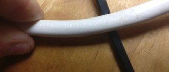
The cable laid in the grooves must be three-core. The use of cables of the VVG family (copper cores, core insulation and outer sheath made of PVC, without armor) is widespread, most of which can be laid in a groove without additional corrugated protection. The VVG-p (flat) model is popular due to the need for a shallower groove.
The power supply to the apartment is turned off - the switch on the input machine is moved to the lower position.
If the ratings of the circuit breakers available in the panel do not allow connecting an additional socket to one of them, another circuit breaker (AB) - one- or two-pole - is installed on the DIN rail.
Connecting a socket to a single-pole circuit breaker
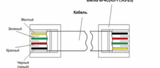
One line must pass through a single-pole AV - a phase line, which it will turn off when the current parameters in it jump. The conductors in the cables have the following insulation color coding:
- phase - red, black or brown (less often - white, gray,
- orange, pink);
- zero - blue or light blue (less often - blue with a white stripe);
- grounding – alternating longitudinal yellow and green stripes.
According to the PUE, the power must be connected to the fixed contact of the fuse. In a circuit breaker, the fixed contact is the top terminal, so the power input is connected to it.
The cores of the cable supplied for connection to the machine are identified, after which the phase conductor is cleared of insulation at a section approximately 1 cm from the end and inserted between the contact plates AB.
note
Then the two remaining cable wires are stripped of insulation to the required length, after which the grounding conductor is connected to the grounding bus of the shield in the mini-box, and the zero conductor is connected to the “zero” of the entrance to the apartment.
Final operations - in the distribution box, using one of the methods (terminal blocks, welding, soldering), wires of the same color are connected to each other, after which a socket is connected to the cable from the junction box and installed in the socket box.
Connecting a socket to a two-pole circuit breaker
A two-pole circuit breaker monitors the situation on two lines simultaneously, and if the current parameters on any of them jump, it turns off the power on both. Such AVs are installed on lines through which power is supplied to some complex equipment, for example, powered by a rectifier.
To connect the cable to a two-pole circuit breaker, the ends of the wires are also stripped. Of the three conductors, the grounding wire is separated and connected to the free terminal of the grounding bus of the panel, and the two remaining wires are connected to the lower terminals of the circuit breaker, taking into account its phasing - to the phase terminal - phase, to the zero - “zero”.
Connecting an outlet to a panel without grounding
According to the PUE, installation of sockets without grounding is allowed only in dry rooms - for connecting low-power devices, but in the wiring of old houses there is often no grounding conductor.
In this situation, sockets with or without a contact for connecting a grounding wire are suitable for use - the grounding terminal remains free and does not interfere with installation.
This operation differs from connecting a grounded outlet only in the absence of the need to use a three-core cable. Accordingly, everything related to the grounding conductor is excluded from the list of works.
Conclusion
If there is a grounding line in the apartment electrical network, you should select for additional installation only a socket with a grounding contact.
Grounding is an additional safety factor for residents, and this circumstance cannot be neglected for the sake of the lower cost of a two-core cable and the fewer number of its connections. In addition, the grounding conductor also protects equipment from accumulating static electricity.
And connecting a modern socket to an individual circuit breaker on the panel is within the power of most home craftsmen, but with the obligatory observance of safety precautions when performing electrical installation work.
Source: https://votetoremont.ru/process-remonta/elektromontazhnye-raboty/podklyuchenie-rozetki-k-avtomatu-v-shhitke/
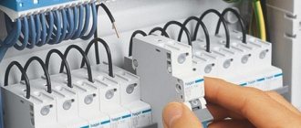
Construction and connection of a distribution board with automatic machines.
Of course, anyone would be intimidated by so many wires when opening the front cover. But believe me, everything is very simple here.
We will analyze everything in order, and at the end we will draw a general wiring diagram. Let's start from top to bottom.
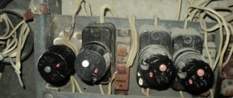
Zero block.
“Zero” it is called because the zero wire
, coming from
the main machine
.
As a rule, the neutral core has a larger cross-section
and is connected under the first screw.
There is also a grounding wire coming to the “zero block”, but it is not visible in the photo - it is not connected because my house belongs to the old housing stock, although it was built in the mid-90s.
Remember. The “zero block” collects all the zeros from the wires that are laid around the apartment. The grounding is located here, but on a separate plate, and is not physically connected to zero in any way.
Let's deal with phase conductors.
The phase conductor coming from the main machine is connected to the input of the first machine
, and
by jumpers
to the inputs of all automatic switchboards.
But from the outputs of all machines, the phase is distributed to the distribution boxes of each room.
As an example, I show how it was done for me. The first four machines go to lighting, the second four machines go to sockets, and the last three go to split systems and a storage tank. They are not needed at the moment and are therefore turned off. See how convenient everything is.
How to connect several machines and how to more reliably connect the zero bus in the panel
Greetings to you, reader of the site www.ceshka.ru.
Today I present to your attention another article from experienced electrician-practitioner Sergei Panagushin from Izhevsk. By the way, Sergei recently had a son - you can congratulate him)))
Sergey has already shared his practical experience in electrical installation on my website; I recently published his article “Tool for stripping wires and cables. Part 1.” and “Tool for stripping wires and cables. Part 2."
This time Sergey will tell you how to connect switching devices in distribution panels - using a special comb or homemade jumpers from mounting wire, and will also tell you how to connect the zero bus. So, I give the floor to Sergei Panagushin.
Basic rules for installing household electrical networks
The main regulatory document regulating the activities for the arrangement of electrical networks is the Rules for the Construction of Electrical Installations (PUE) . Before you begin installing electrical wiring yourself, you should familiarize yourself with the PUE and especially carefully study the sections related to the selection of equipment, installation rules and safety precautions.
Basic rules to follow when installing electrical wiring:
- Distribution boxes, meters, input panels, switches, sockets and other key network elements are mounted in easily accessible places .
- The switches are located on the side of the vestibule, inside the room. Installation height – 60-150 cm from the floor . Wires to switches are supplied from above.
- Sockets are located at a height of at least 50 cm from the floor, the maximum allowable distance is 80 cm . Wires to sockets are supplied from below. Sockets must be located more than 50 cm from powerful current consumers, a gas stove and grounded elements related to other communications.
- Sockets are installed at the rate of 1 pc. for 6 m² of space, excluding the kitchen. In the kitchen, the number of sockets corresponds to the number of electrical appliances. Sockets cannot be installed in the toilet; the socket group in the bathroom is connected through a separate transformer, or a stationary extension cord with a plug is installed, which is plugged into one of the sockets in the kitchen as needed. In this case, it is advisable to separate it into a separate connection group.
- Wire routes must be strictly vertical or horizontal . Turns are made only at right angles. The location of all cables must be marked on the plan.
- Cable laying routes are located at a strictly defined distance from the load-bearing elements of the ceiling, pipes, and edges of openings.
- The wires are laid so that they do not come into contact with metal elements of building structures.
- The distance between the wires laid in one channel is at least 3 mm, or each of them must have individual protection (channel or corrugation).
- Wiring and connections are carried out in junction boxes. All connections must be insulated; connections of copper and aluminum wires are not allowed.
- To attach protective and neutral conductors to devices, bolted connections are used.
Panel, counter, machines and socket - Community "Garage Affairs" on DRIVE2
Since there was no light at all in the garage, initially it was necessary to install a meter and run the wiring to it. As always, my luck at the “MIRACLE of the Masters” was in action.
An electrician from a cooperative, a rather strange man, considering that he lives in a cooperative, on the second floor of his garage. Anyway.
I gave him a machine meter and a socket with a panel with the agreement that he would arrange all the equipment into a panel, and the next day everything would be ready in my garage (Wednesday). I asked for 1000 rubles.
Important
We agreed and then off we went, either busy, sick, or some other crap! Due to being busy at work, I couldn’t go and give him a kick for a week. And so on Friday evening I went to see this ghoul, chased this asshole all over the garage, saying that the horse lay down (where did he find it in the garages?!), after which he took everything he bought and went home.
Early in the morning I sat down to assemble the shield myself, although I was undertaking to do it for the first time, I was completely confident that I would do it perfectly and it seems that it turned out that way)
What we have: 1. Double circuit breaker for 25A (used as a switch), installed before the meter.2. Two single 25A circuit breakers, one for sockets in the garage, the other for an socket in the panel.3. One single 16A circuit breaker for lighting in the garage.4. Actually the shield itself (for some reason I visually liked the metal one).5.
Mercury meter 201.5.6. Two zero buses, one isolated, is used as a general phase distribution and the second, respectively, for its intended purpose for ZERO.7. 1 meter of copper cable with section 4.8. 7 meters of AVVG aluminum cable with a cross-section of 6 (the wiring to the garage is very old and made of aluminum).9. Corrugation (got a bunch for free).10.
Fasteners for corrugated walls.
11. Self-tapping screws with a dowel for fastening.
And now about the main thing!) I covered a piece of the metal plate on which I actually installed the elements with a film under polished aluminum) because there was nothing better to do) and then away we went.
Layout
We twist, twirl, bend the wires and do everything according to Feng Shui.
An hour and a half later, all the elements were installed as desired and everything was very neat!
On Saturday afternoon I went to the cooperative and kicked the chairman to force that asshole to install the assembled panel on the wall and connect it to the general network. In my understanding, installing a meter means twisting the wires with the street ones and putting a seal.
How to route wires
When installing sockets in the house, before connecting them, you need to determine what kind of network there will be - external or internal. From the names, the difference between the two installation methods is clear: in the first case, installation is carried out on top of the walls, in the second, the wires are hidden inside. Each method has its own advantages and disadvantages, which you need to know about in order to make an informed choice.
External wiring
Special boxes (cable channels) are used in which the wires are laid. Their cost will not be particularly noticeable in the overall price of electrical wiring. A simpler option is mounting on brackets. But then the cable will not be protected.
Advantages:
- Before connecting the sockets, you don’t have to scratch the wall and seal it after work. It is more convenient to expand the network.
- Installation does not require the use of special tools.
- Quiet operation.
- In the event of a wiring break or breakdown, it is easy to find the problem area; there is no need to open the wall.
- High speed - 2–4 times faster than installing hidden wiring. During the execution of the task, there will be no force majeure events such as a broken tool or a fallen piece of wall.
Flaws:
- Cables are not protected from external influences - electromagnetic radiation, mechanical damage, temperature changes. The wire sheath gradually wears out, even if it is in a cable channel.
- Aesthetic unattractiveness. An external network can ruin the interior of the room. But if you use your imagination, it is possible to make it an advantage, to beat it profitably.
- If the walls are wooden, you will need special fasteners that allow you to distance the wiring by 5–10 mm.
This method is justified if the network being created is temporary or will be expanded in the future. If you plan to add 1-2 access points, it is better to perform a hidden installation - you can run the socket from the socket along the wall.
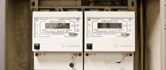
Apartment panel. Replacing machines and installing RCDs
Apartment panel, how to replace circuit breakers and install an RCD in the apartment panel? In the previous article, I replaced the CO-505 meter in the apartment panel with a Mercury 201 meter. Now we need to replace the machines and install an RCD in the apartment panel ; this must be done for several reasons. The photo below shows the apartment panel and the diagram of the panel from the developer at the time of delivery of the house.
Why is it necessary to change the automatic devices in the apartment panel and install an RCD? Because the apartment panel was assembled by the developer with gross violations, namely:
firstly , the cross-section of the PPV input wire (colloquially called “noodles”), which comes from the floor panel to the apartment panel, is 4 sq. mm.
and on such a wire, to protect it, an input circuit breaker of no more than 25A is installed, and the developer installed an input circuit breaker of 40A in the apartment panel, i.e. It turns out that in case of high load in the apartment, our input wire will melt, and the 40A circuit breaker will not turn off.
Therefore, it is necessary to install a 25A input circuit breaker in the apartment panel to protect the PPV wire of 4 sq. mm;
secondly , the outgoing circuit breakers in the apartment panel are set to 25A, which is also a gross violation.
Because all household sockets are designed for a current of no more than 16A, and even then, if these sockets are from quality manufacturers, and if they are from Turkey or China, then there will not be 16A there.
The lights and sockets in the apartment are connected with a 3x2.5 PPV wire; one wire from the 25A circuit breaker in the apartment panel goes to both the light and the sockets. We will install circuit breakers with a rated current of 16A in the apartment panel so that our sockets do not melt;
thirdly , we will throw out all the Chinese IEK automatic machines and install more reliable ABB automatic machines of the “home” SH 200 series in the apartment panel;
fourthly , we will install in the apartment panel an RCD from ABB “home” series FH 202 with a rated current of 40A, a step higher than the 25A input circuit breaker. Well-known brands ABB, Schneider Electric, Legrand do not have RCDs for 32A.
I note that we installed a 50A RCD with a leakage current of 30 mA in the floor panel, but again, this is Sassin from China, which you should not trust with your life.
note
But we will not remove the Chinese RCD in the floor panel; we will leave it as additional differential protection.
Because If we add an RCD to the apartment panel, then the layout of the apartment panel will change relative to the original panel diagram from the developer.
Apartment panel. Scheme.
Let's start replacing the machines and RCDs in the apartment panel. The first thing to do is to turn off the input circuit breaker and the RCD in the floor panel.
Then we unscrew the metal panel (plastron) in the apartment panel and “mark” the wires with electrical tape, blue for the working zero N, yellow-green for protective PE, we don’t touch the phase wire, it remains white. You can apply markings with a regular pen or marker, but you need to be careful with the wires so as not to erase the inscriptions.
Our wires are all white (the developer, as usually happens, saves on everything) and it is easy to confuse or forget where in the apartment panel we have a phase, where is zero, and where is the protective conductor.
After this, you can unscrew the wires from the machines. The zero working and protective conductors of the outgoing lines to the apartment can not be touched, because Our machines will be single-pole. First, we install it in the apartment panel on a DIN rail and connect the ABB 25A input circuit breaker. PPV wire 4 sq. mm. Ours is mono-core, so there is no need to crimp it with the NShVI ferrule.
Next, we install and connect into the apartment panel according to the diagram a 40A ABB RCD with a leakage current of 30 mA. We connect the RCD in the apartment panel with a PV-3 stranded wire, the ends of which are crimped with gray NShVI sleeve lugs for 4 sq. mm.
We install single-pole (single-module) ABB SH 201 16A circuit breakers on a DIN rail in the apartment panel
We will connect the single-pole circuit breakers in the apartment panel with a comb, which we still have after dismantling the IEK circuit breakers.
You should pay attention to ensure that the comb fits, because... It happens that machines and combs from different machines do not fit together well.
The comb is not installed quite level, because... The photo was taken even before the machine contacts were tightened.
Important
We connect the phase wires of the outgoing lines to single-pole circuit breakers in the apartment panel.
We check the tightness of the contacts of the machines and the RCD. We supply voltage to the apartment panel by turning on the RCD in the floor panel. We turn on the 25A input circuit breaker, check the operation of the RCD by pressing the “TEST” button, it should turn off. Next, we supply voltage to consumers in the apartment by turning on single-pole circuit breakers.
If everything works for us, the light is on, then we cover the machines and RCDs in the apartment panel with a metal panel and paste the designations of the machines and RCDs into the apartment panel.
Well, that’s all, we installed and connected ABB automatic circuit breakers and RCDs to the apartment panel. I think that everyone needs to inspect the apartment and floor panels, and, if necessary, eliminate errors, because the electrical safety of your family, house or apartment depends on this, first of all.
Thank you for your attention.
The entry was published in the Electrical section and tagged Automatic devices, RCDs. Bookmark the permalink.
Source: https://elektroschyt.ru/kvartirnyj-shhitok/
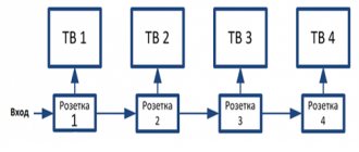
Block diagram of electrical wiring in the room.
As you know, in any residential building there is a switchboard
, in which there are counters and machines. So, this shield is like an intermediary between the electricity supplier and us, the consumers of electricity.
The power cable is connected to the distribution board
, from which the supply voltage “phase” and “zero” is taken and directly connected to the
input of your electricity meter
.
From the counter output
the supply voltage is supplied to
the input of the main circuit breaker
or
RCD
, and from
the output of the main switch
the voltage is supplied to the apartment or living space. Next I will talk about the apartment, since the voltage distribution circuit is standard for all rooms.
As a rule, a central junction box
, into which the power cable from the machine or RCD enters.
In the picture above, the central distribution box is located in the hallway. So, the installation of all electrical wiring in the apartment begins from this junction box .
Now from the central box
In each room, lines are laid to
the distribution boxes
of the room.
And from the distribution boxes,
the wires are routed around the room to the places where
the switch
,
sockets
,
chandelier
or
lamps
.
This is a standard electrical wiring diagram, but it is not entirely convenient because if you need to replace the socket, then you will have to turn off the general power supply, located in the distribution panel on the landing and supplying voltage to the apartment. And here it turns out that while the socket is being replaced, the entire apartment remains without voltage.
But this scheme has been slightly improved and instead of the central distribution box, a small distribution board with automatic switches is now installed, which is mounted directly in the apartment.
Very comfortably. You need to replace an outlet, a chandelier, or suddenly a short circuit occurs - only a specific circuit breaker turns off, but everything else works.
The point of this article is precisely to tell you about the design of such a shield, and to show how, with its help, you can make wiring in an apartment with your own hands.
How to connect a switch from an outlet, how to make an outlet from a switch
The development of an indoor electrical network can be planned both during its initial design and during the operation of ready-made wiring. In any case, you want to connect distribution boxes, mounted socket boxes, and switches with each other with minimal material costs.
Disconnection of the power cable is not necessarily carried out exclusively in installation boxes, which are hub splitters. For example, there are many ways to connect a switch to an outlet, and vice versa. Some of the switching can be done in any box, the main thing is that there is no danger of shorting the contacts.
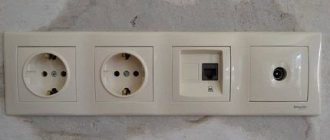
A typical example of combining a socket and a switch in one unit
Often in a corridor or hallway there is a need to combine a network connection point (socket) and a switch for several lighting groups. This method solves several problems:
- An extensive electrical outlet network in the corridor is usually not needed: there are no constantly used electrical appliances. However, there is a need to connect a vacuum cleaner or charger. In addition, a radiotelephone base unit can be installed in the hallway.
- There is little space on the walls in this room; there are wardrobes, a mirror, and a hanger. Part of the corridor is usually occupied by the input switchboard and metering device (meter). Therefore, compact placement of switching equipment is a key issue.
- By combining the socket and switch, wiring is saved and installation of an additional junction box is not required.
- If you additionally connect a second device: a switch to a socket, or vice versa, there is no need to damage the wall or organize a route for the power cable. The connection is made with minimal impact on the room.
Block diagram of electrical wiring in the room. Improved.
You won't see anything fundamentally new here. A distribution board with automatic circuit breakers is added to the circuit, and lines are laid from it to the distribution boxes of each room.
As you can see, everything is simple. Power cable from the main machine
comes to your
switchboard
, and from the shield the voltage goes in two lines to the distribution boxes in each room. Where the first line is lighting, and the second is sockets.
But this structural wiring diagram will only be valid for residential premises of the old foundation, that is, those built during the Soviet Union and the early 90s - the so-called TN-C grounding system. At that time, for residential premises, no special requirements were attached to grounding, and there were practically no household appliances for which it was necessary to maintain a separate grounding bus.
Only circuit breakers were residual current devices, and therefore this type of protection was considered the norm. But technology does not stand still and improved and improved devices of this type have already appeared on the market.
Therefore, now, to protect people from electric shock, taking into account the existing equipment, the standards have been supplemented and revised, and in new buildings it is allowed to use only the TN-S grounding system.
Selecting the type of electrical installation
The first thing you need to start with is to decide on the method of installing the line. Today, open and hidden wiring is used. Open electrical wiring involves fastening all the constituent elements on top of finished walls (the routes are laid in special cable channels).
Open line routing
The advantage is as follows:
- the damaged area can be repaired without any problems (no need to cut wallpaper, destroy plastered walls, etc.);
- simpler installation and preparatory work (no need to tap the walls along the electrical wiring in the house);
- convenient to add new branch points.
This installation method has one disadvantage - very often it does not fit into the overall interior of the rooms since the cable channels do not have a very attractive appearance.
Hidden electrical wiring in the house is becoming more popular. In this case, wires and cables are laid in the walls; for this purpose, grooves are drilled - grooves in the walls, ceiling and floor or behind the suspended ceiling and wall cladding.
Advantage:
- does not spoil the interior of the rooms with its appearance;
- is fireproof;
- cheaper than outside.
- the likelihood of damage is much less;
- high durability of all elements.
Among the disadvantages are:
- complexity of repair and operation (to replace the electrical wiring in the house or connect a new point, you need to open the wall decoration;
- when a breakdown occurs, it is very difficult to find the exact location of the breakdown unless you use special devices, for example, a homemade metal detector;
- prohibited in a wooden house, according to PUE 7.1.38.;
- Electrical installation work requires more experience and a set of tools.
We recommend that you still opt for the latter method, since it is more durable and the entire line is not striking! When choosing high-quality components and correctly installing electrical wiring in the house, the likelihood of a breakdown is extremely low.
Basic types of sockets for the home
Before you connect an outlet, two or a whole block of such elements, you should decide on their type. Most specialists and homeowners who independently carry out the connection have to deal with the following options: • Type “C” , the simplest and most convenient for connection. Includes only 2 contacts - “zero” and “phase”.
It has been used for several decades and is practically the only option for old housing. Does not always fit some modern appliances, so it is usually replaced with more modern electrical outlets. • Type “F” , Unlike the previous version, it is additionally equipped with grounding contacts (which, however, remain unused if the electrical network diagram does not provide a grounding loop).
The product is suitable for most devices, except for equipment with a round rim and no side cutouts. • Type “E” , the “phase” and “zero” sockets do not differ from the “F” sockets. The difference lies in the grounding, which has the form of a small pin protruding from the plastic.
The products are not in particular demand among domestic consumers and electricians. Although most electrical appliances are suitable for such sockets. There are other types of classification of electrical outlets - including according to the level of protection of the housing from the ingress of liquid and foreign objects. IP22 and IP33 class models are suitable for ordinary residential and domestic premises. In a children's room, it is advisable to install a product made according to the IP43 standard, the difference of which is special curtains that protect the child from contact with live contacts. For bathrooms, showers and the cooking area (kitchen or that part of the studio apartment where the sink is located), choose the IP44 class option, which prevents short circuits due to splashes on the product.
Where to start
Installation of new electrical wiring should always begin with studying the PUE - Electrical Installation Rules, namely section 7.1 regarding home electrical wiring.
If you decide to connect a new home electrical network with your own hands, you will need to study the rules for laying the network in order to avoid mistakes that could lead to an accident and even a catastrophe - even the death of a person.
If you logically decide to entrust the installation of new electrical wiring to a specialist, knowing at least the basic rules will help you control his work.
Before installing electrical wiring, you need to decide on the following key points.
Decide on the type of input - single-phase (220V) or three-phase (380V). In the vast majority of cases, single-phase is used.
Three-phase input of electrical wiring is advisable only if the premises have a workshop or workshop where three-phase asynchronous motors or similar equipment operate.
Next, you need to develop a wiring diagram. This is a detailed marking on the plan of an apartment or house of the locations of sockets, switches, main current consumers and - most importantly - the lines going to them from the distribution panel. In case of complex work, a technological map is drawn up with a detailed description of the procedure.
It is imperative to calculate the total power of the maximum one-time energy consumption of all appliances in the house - it is not recommended if it exceeds 5.5 kW, since large amounts of power are usually not allocated for domestic purposes.
The maximum number of consumers that will be allowed to work simultaneously is taken into account. Usually this is a refrigerator, lighting systems, computer and router, TV, heating systems (if electric), split system, washing machine.
What are the advantages of this method
Hidden electrical installation is used during major home renovations or replacement of wiring with a new, more powerful one.
The advantage of hidden cable routing inside the walls is as follows:
- The interior of the rooms does not deteriorate, because... electrical wiring will be hidden under a layer of plaster or in plasterboard partitions.
- Increased fire safety of housing if the walls are concrete and not wooden (or, for example, made of plaster or other non-combustible material). This is due to the fact that when the insulation ignites, the fire will not spread further due to the lack of oxygen and flammable materials.
- Increased service life of the electrical network due to reliable protection of the cable from ultraviolet and mechanical influences.
Disadvantages include the complexity of installation compared to the open method, as well as the complexity of repair and maintenance of hidden electrical wiring. The last two disadvantages are due to the fact that all wiring elements are hidden under a layer of plaster and access to them will require destruction of the wall finish.
To summarize, it should be noted that, nevertheless, for permanent housing, this option for laying cables is correct and reliable. As for bathhouses, garages, log houses and other buildings, it is recommended to install open electrical wiring.
We've sorted out the advantages, let's move on to the main question of the article!
Marking
Determine at what height the sockets and switches will be located; the easiest way is to measure the lines of sockets and switches from the ceiling, because the floors in apartments are most often crooked. For example, if the height from floor to ceiling after renovation will be 250 cm, and you want to raise the sockets by 30 cm, measure 220 cm from the ceiling. If there are several sockets and switches in one group, draw a horizontal line along the level and place a mark every 7 cm (socket box size 71mm), the same applies to vertical groups.
For lovers of standards, so that it is “like everyone else” or “how they do it” - remember, they do not exist! There are requirements for children's institutions, kindergartens and schools, where sockets and switches are installed at a height of at least 160 cm. Everything else, especially in your home, you can do as you wish. For example, some make sockets in window slopes or even in the floor.