What is a resistor
A resistor is resistance.
It is a passive element in the circuit and is only capable of reducing current. The origin of the name comes from the Latin “resisto”, which literally means “I resist” in Russian. A conductor is designed to convert voltage into current and vice versa; it absorbs some of the energy and limits the current. The main application is in electrical and electronic devices.
Reference! The connection of conductors can be serial, parallel or mixed.
There are also two types of semiconductors:
- linear, the resistance of which does not depend on current and voltage;
- nonlinear, capable of changing resistance depending on the values of the flowing current and voltage.
The main parameter of resistors is the rated voltage.
What does it look like
Elements can be wire or non-wire. The latter will perfectly perform their function in a high-frequency circuit; their appearance and manufacturing process are different. There are resistors for general use and special ones. The former do not exceed 10 megaohms, while the latter are capable of operating at voltages of 600 volts and higher. They also differ in appearance. In the photo below it is easy to see the difference and understand what the resistor looks like.
Difference in appearance and size
What does it consist of?
By winding the wire around a frame made of ceramic or pressed powder, you get a wirewound resistor. In this case, the wire itself must be made of nichrome, constantan or manganin. This will create a semiconductor with high resistivity.
Non-wire elements are made on a dielectric basis from conductive mixtures and films. They are divided into thin-layer and composite, but they all have increased accuracy and stability in operation.
The adjusting and tuning elements are a ring resistive plate along which the slider moves. It slides in a circle, changing the distance of the points on the resistive layer, as a result the resistance changes. You need to understand what a resistor does for a device.
What is it used for?
What is a resistor for? Using this part in an electrical circuit, you can limit the amount of current conducted; as a result of a correctly selected part, it is easy to obtain the required value. The higher the resistance, the lower the output current will be, provided the voltage is stable.
It’s easy to understand how resistors work; they can be used as a voltage-to-current converter and vice versa, in measuring devices they are used to divide voltage, and they can also reduce or completely eliminate radio interference.
Designation on diagrams
In Russia and Europe, the resistor in the diagram is indicated by a rectangle with dimensions of 4 * 10 mm. There are symbols to determine resistance values. The permanent element in the diagram is designated as follows:
Designations of permanent elements in the diagram
Variables, including tuning ones, as well as non-linear ones as follows:
Designations of variable conductors
Important! There is always an error in the resistance declared by the manufacturer; it is indicated using letters and numbers in percentage terms.
Types of resistors by manufacturing method and their features
Constant resistances are made in several ways. The properties change to some extent depending on the production method, so you also have to know the types of resistors based on the manufacturing method. They are:
- Wire.
- Non-wire: metal;
- compositional;
- foil (metal foil);
- graphite.
The most “ancient” ones are wire ones. They are also the most inexpensive. But non-wire ones can have a very small permissible deviation from the nominal value and some other useful features.
Wire
Wirewound resistors are a piece of metal wire wound around a ceramic base. The wire used is special - constantan for ordinary ones, nichrome for high-resistance ones. The top turns of wire can be:
- filled with ceramics;
- covered with enamel or varnish.
Some types of wire-wound resistors can be distinguished externally: in a ceramic rectangular case and tubular type (C5-35B or PEVR). They are clearly different from others. At the same time, they cannot be either thin-layer or composite.
This is what wirewound resistors of different types look like
Others are almost the same in appearance. Except that with comparable denominations they will be larger in size. This is understandable - the wire takes up more space. Depending on the installation method, wirewound resistors can be used for mounting on printed circuit boards (with mounting taps) or for surface mounting. In the latter case, fasteners must be pre-installed on the board.
If you break the body of the wirewound resistor, we will see the following picture
They have one feature: significant parasitic inductance. Because of this, resistance wires are not used in circuits operating with high-frequency alternating voltages. For networks of direct voltage or alternating, but low frequency (50 Hz, for example), they are suitable.
Non-wire
Most modern resistors are made without wire, but many of them are made using a similar technique. A layer of conductive substance is applied to the dielectric base. It can be a metal, alloy or composite material. Therefore, they are usually called “film”. Based on the layer thickness, this type of resistor is divided into thin-film (from fractions of a micron to 1-2 microns) and thick-film. The thinner the film, the higher the resistance. To obtain larger denominations, a groove can be cut into the film. The film can be covered with a protective layer (oxide film or varnish, paint), or another layer of ceramics can be applied. Of course, when using different materials, technological processes change, but in general the manufacturing scheme is as follows.
The structure of film resistors of different types
So, here are the types of film resistors:
- Metal. This is one of the most common types of resistors, as they have sufficient accuracy and low cost. Metals used are chromium, palladium, tantalum; alloy - nichrome; metal ceramics - cermet. Nichrome film resistors are mainly produced, since they have a low temperature coefficient of resistance (with a change in temperature, the resistance almost does not change), they heat up little, and have stable parameters. They are smaller in size compared to carbon ones.
- Compositional . Instead of metal, composites are applied to the ceramic base. 13 types of elements of this type are produced. All of them can be divided into two groups - high-resistance and high-voltage (from 2.5 kV to 60 kV). Designed for operation in AC and DC circuits. Their main disadvantage is the high level of current noise - from 15 to 40 µV/V.
- Foil. Thin or super-thin foil is glued onto the dielectric body and covered with a layer of dielectric on top. This technology makes it possible to obtain high-precision resistors (precision and super-precision). Metal foil resistors are characterized by very high stability of parameters, including their value almost does not change with changes in the applied voltage. But the main advantage is that they make little noise. Therefore, they are used in amplifiers, receivers/transmitters, measuring instruments and special equipment.
- Coal or carbon. Graphite is used as a conductive layer. They can be film type or volumetric. The nominal values range from 10 ohms to 10 megohms. Their advantages are that they can be used in high-frequency devices, a wide range of operating temperatures - from -60°C to +125°C, and have a low noise level. The downside is that they get very hot. The conductive graphite layer can be heated up to 120°C (this mode can be withstood for a long time). Can be used in alternating, direct and pulsed current circuits.
So what types of resistors are best to use? If you need stability of parameters and low noise level, metal foil or film metal or metal-ceramic ones are suitable. They can also be used in circuits operating at high frequencies. If there are no special requirements (for constant voltage or with a frequency of 50 Hz), there is no point in paying attention to the types of resistors according to the production method. Look for the right denomination and required characteristics.
Types of resistors
Resistors come in three types:
- Constant - the resistance value of which does not change. It should be noted that small changes do occur due to temperature changes. But these changes are not significant, since they do not affect the operation of the circuit.
- Variables - their resistance varies within certain limits. For example, rheostats. When we turn a radio knob to change the sound or move a slider, we change the resistance of the circuit.
- Adjustable - change the value using a screw. This is rarely done to obtain the desired circuit parameters.
Classification of resistors
Resistors differ not only in their ability to adjust resistance. They can be made from different resistive materials, have different numbers of contacts, and have other features.
By type of resistive material
The elements can be wire, non-wire or metal foil. High-resistance wire is a feature of a wire element; alloys such as nichrome, constantan or nickel are used for its manufacture. Films with increased resistivity are the basis of non-wire elements. Metal foils use special foil. Now let's find out what resistors are made of.
Semiconductor design
Non-wire are divided into thin-layer and composite, the thickness of the former is measured in nanometers, and the latter in fractions of a millimeter. Thin-layers are divided into:
- metal oxide;
- metallized;
- borocarbons;
- metal-dielectric;
- carbonaceous.
Composite ones, in turn, are divided into volumetric and film. The latter can be with an organic or inorganic dielectric. To understand whether a resistor has polarity, you should know that their sides are identical.
By purpose resistance
Permanent and variable semiconductors also have some differences in characteristics. Permanent ones are divided into general and special purpose conductors. The latter may be:
- high frequency;
- high voltage;
- high-megaohm;
- precision.
Such parts are used in precision measuring instruments; they are particularly stable.
Variable resistors can be divided into trimming and adjusting. The latter can be with a linear or nonlinear functional characteristic.
By number of contacts
Depending on the purpose of the resistor, it may have one, two or more contacts. The contacts themselves are also different, for example, for SMD resistors it is a contact pad, for wire resistors it is a special wire composition. There are metal film resistors with quantum point contacts, and in variables they are moving.
Different number of contacts on elements
Other
Resistors differ in the shape and type of resistance, as well as in the nature of the dependence of the resistance value on voltage. The description of the dependence of a quantity can be linear or nonlinear. Using the element is simple, the capacity is indicated on the body, minus and plus are the same.
Resistors may or may not be sealed against moisture, and the housing may be varnished, vacuum sealed, sealed, pressed into plastic, or compounded. Nonlinear ones are divided into:
- varistors;
- magnetoresistors;
- photoresistors;
- posistors;
- strain gauges;
- thermistors.
They all perform their specific function, some change resistance based on temperature, others on voltage, and others on radiant energy.
Resistors for general and special purposes
Variable servo resistor and 25 and 10 W power dissipation resistors
The industry produces resistors for general and special purposes. General-purpose resistors are used as anode loads of radio tubes and dividers in power circuits, filter elements, volume and tone controls, in pulse-forming circuits, and in low-precision measuring instruments. This group includes fixed resistors, the resistance of which is fixed during manufacture, and variable resistors, the resistance of which can be smoothly changed within certain limits. General purpose resistors have resistances ranging from 10 ohms to 10 megohms, and rated power dissipation ranges from 0.125 to 100 watts.
Resistors for special purposes, which have a number of specific properties and parameters, include high-resistance, high-voltage, high-frequency, precision, and semi-precision.
- High-resistance resistors are predominantly of the composition type with a resistance of up to 1013 Ohms and are used in devices for measuring low currents. Their rated power dissipation is usually not indicated, and the operating voltages are 100-300 V.
- High-voltage resistors with a resistance of up to 1011 Ohms, but higher power and larger in size than high-resistance ones, are used for voltage dividers, antenna equivalents, spark extinguishing, and discharge of filter capacitors. The most common types have operating voltages in the range of 10-35 kV.
- High-frequency resistors are designed for circuits operating at frequencies above 10 MHz; they are used as matching loads, attenuators, antenna equivalents, waveguide elements and have low intrinsic capacitance and inductance. With artificial cooling, their rated powers are 5, 20, 50 kW.
- Precision and semi-precision resistors used in precision measuring devices, computers, relay systems, resistance stores are distinguished by high manufacturing precision, have increased stability of the main parameters and are often sealed. Their nominal resistances are from 1 Ohm to 1 MOhm, and their nominal power dissipation is no more than 2 W.
Types of resistors
There are many types of resistors that are used in the electronics industry. Let's look at the main ones.
Fixed resistors
Constant resistors look something like this:
On the left we see a large green resistor that dissipates a lot of power. On the right is a small tiny SMD resistor that dissipates very little power, but still performs its function perfectly. You can read about how to determine the resistance of a resistor in the article marking resistors.
This is what a constant resistor looks like on electrical circuits:
Our domestic image of a resistor is depicted as a rectangle (on the left), and the overseas version (on the right), or as they say - bourgeois, is used in foreign radio circuits.
This is how power is marked on Soviet resistors:
Next, the power is marked using Roman numerals. V – 5 Watt, X – 10 Watt, L -50 Watt, etc.
What other types of resistors are there? Let's look at the most common ones:
20 watt glass with wire leads, 20 watt with mounting tabs, 30 watt in vitreous enamel, 5 watt and 20 watt with mounting tabs
1, 3, 5 watt ceramic; 5,10,25, 50 watt with conductive heat exchange
2, 1, 0.5, 0.25, 0.125 watt carbon structure; SMD resistors of standard sizes 2010, 1206, 0805, 0603,0402; SMD resistor assembly, 6,8,10 pin resistor assemblies for through-hole mounting, resistor in DIP package
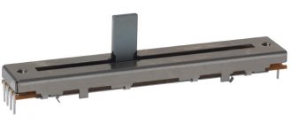
Variable resistors
Variable resistors look like this:
On the diagrams they are indicated as follows:
Accordingly, domestic and foreign versions.
And here is their pinout (location of pins):
The variable resistor that controls the voltage is called a potentiometer, and the one that controls the current is called a rheostat. Here lies the principle of a voltage divider and a current divider, respectively. The difference between a potentiometer and a rheostat is in the connection diagram of the variable resistor itself. In a circuit with a rheostat, a variable resistor connects the middle and outer terminals.
Variable resistors whose resistance can only be changed using a screwdriver or hex wrench are called variable tuning resistors. They have special grooves for adjusting the resistance (marked with a red frame):
And this is how trimming resistors and their connection circuits in rheostat and potentiometer mode are designated.
Thermistors
Thermistors are resistors based on semiconductor materials. Their resistance depends sharply on the ambient temperature. There is such an important parameter of thermistors as TCR - thermal coefficient of resistance. Roughly speaking, this coefficient shows how much the resistance of the thermistor will change when the ambient temperature changes.
This coefficient can be either negative or positive. If the TCR is negative, then such a thermistor is called a thermistor, and if the TCR is positive, then such a thermistor is called a posistor. For thermistors, as the ambient temperature increases, the resistance decreases. For posistors, as the ambient temperature increases, the resistance also increases.
Since thermistors have a negative coefficient (NTC - Negative Temperature Coefficient - negative TCS), and posistors have a positive coefficient (RTS - Positive Temperature Coefficient - positive TCS), they will be designated accordingly in the diagrams.
Varistors
There is also a special class of resistors that sharply change their resistance as the voltage increases - these are varistors.
This property of varistors is widely used to protect against overvoltage in a circuit, as well as against pulsed voltage surges. Let’s say our voltage “jumped”. The varistor “snapped” the whole thing and immediately sharply changed the resistance downward. Since the resistance of the varistor has become very small, all electric current will immediately begin to flow through it, thereby protecting the main circuit of the radio-electronic device. In this case, the varistor takes all the power of the pulse onto itself and very often pays for it with its life, then it burns out completely
In the diagrams, varistors are designated as follows:
Photoresistors
Photoresistors are also very popular. They change their resistance when you shine light on them. For these purposes, you can use both sunlight and artificial light, for example, from a flashlight.
In the diagrams they are designated as follows:
Strain gauges
The principle of their operation is based on stretching thin printed conductors. When stretched they become even thinner. It's like pulling out chewing gum. The more you stretch it, the thinner it becomes. And as you know, the thinner the conductor, the greater the resistance it has.
In the diagrams, the strain gauge looks like this:
Here is an animation of the strain gauge in action, borrowed from Wikipedia.
Well, as you guessed, strain gauges are used in electronic scales, as well as in various sensors where any pressure or force is applied.
Typical sizes of SMD resistors
The dimensions and shape of these parts are determined by the JEDEC regulatory document. Markings are applied to the housing, which indicate the length and width of the resistor in inches. This is the most common option used by manufacturers, suppliers, and sellers.
For example, 0804 means the part is 0.08 inches long and 0.04 inches wide. In the SI system, dimensions are indicated in millimeters. To convert to millimeters, inches are multiplied by 2.54. Designation of resistor 0804 in the SI system - 2010. Length - 2.0 mm, width - 1.0 mm.
To select the desired type of part and decipher the codes, you can use an SMD resistor calculator or a special “Resistor” program. With their help, you can find out the nominal resistance of an existing resistor or, conversely, find out what the markings for the desired value look like.
Each size of SMD resistor has a certain maximum power dissipation.
| Power, W) | ||
| 0201 | 0,6 | 0,05 |
| 0402 | 1,1 | 0,062 |
| 0603 | 1,6 | 0,1 |
| 0805 | 2,1 | 0,125 |
| 1206 | 3,1 | 0,25 |
The principle of operation of a resistor in simple terms
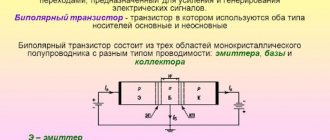
All electronic devices consist of radio components, which are divided into two large types: active and passive.
Active ones amplify electrical signals. A weak signal at the input controls a strong one at the output. In this case, the gain is greater than unity.
The resistor is a passive type of part whose gain is less than unity.
In Soviet times, resistors were called resistances. These days these parts are called resistors. This was done because all parts used in electronics have resistance. To avoid confusion, active resistances are called resistors.
All conductors have resistance, which is considered harmful, since it leads to heating of the element through which the current flows. In addition, electrical power is lost. The value of the resistor is useful. It heats up and produces heat. Heating stoves and lamps used in everyday life operate on this principle.
Principle of operation
When purchasing a part, you need to understand exactly how a resistor works. Any conductor component has certain characteristics due to its internal structure. When an electric current flows through a conductor, charged particles passing through its structure lose their energy reserve, releasing it outward and heating the substance. It is known that the voltage value is equal to the product of the current passing through the conductor and the resistance of the material from which it is made. What does a resistor do? Since it contains a component with a very high resistance to current, when the latter passes through the element, the voltage decreases and some of the power is released in the form of heat.
Operating principle of a variable resistor
Potentiometer circuit
By turning the knob, the length of the resistor changes, and as a result, the current strength. The figure shows a variable resistor with three terminals - a potentiometer. The resistance between ends 1 and 3 varies from 0 to maximum, depending on the position of the handle. The same picture occurs between ends 2 and 3, but in reverse. That is, if resistance 1 – 3 increases, 2 – 3 decreases. When a variable resistor has two ends, we have a rheostat.
The figure shows a rotary variable resistor. There are also sliders, where the slider moves in a straight line. By turning the knob, the resistance changes from zero to maximum. Potentiometers are widely used in audio equipment.
Potentiometer
Potentiometers are recessed into cylindrical and parallelepiped housings. Inside the housing there is a horseshoe-shaped resistive element. Along the axis of the part there is a metal handle, turning which changes the position of the current collector, which is located at the opposite end.
The current collector plate is securely pressed against the resistive element due to elastic force. It is made of steel or bronze. Voltage is applied to the extreme ends of the potentiometer. By rotating the handle, the current collector slides along the resistive element, changing the voltage between the extreme and middle ends.
The figure shows a wirewound potentiometer in which the resistive layer is made of wire. A high-resistance wire is wound around a horseshoe-shaped frame. The contact surface of the ring is then ground and polished. This is done to ensure a reliable connection between the slider and the conductive layer.
Non-wire potentiometers are also manufactured. In them, a resistive layer is applied to a ring-shaped or rectangular base made of insulating material.
Resistor structure from the inside
The simplest resistor is a rheostat. A wire with high resistance is wound around the frame and connected to a power source. Based on this, we can conclude: the first requirement for this element is a high-resistance conductor. To produce this element use:
- wire;
- metal film, metal foil;
- composite material;
- semiconductor.
Metal foil made of high-resistivity material is wound onto the frame. If it is necessary to increase the resistance, it is cut into a track, thereby increasing the length and, accordingly, the resistance. A metal film resistor is produced by sputtering metal onto a base.
Graphite with organic or inorganic additives is used as a composite material. The resistor may consist entirely of such material or of a track on which this material is applied.
With the beginning of the production of microcircuits, new resistors appeared, which are called integrated. Manufacturing is done at the molecular level. A thin layer of high-resistivity metal is sprayed onto a highly doped semiconductor, which acts as a resistor.
The operating principle of a trimmer resistor
After installing parts of an electronic device, its characteristics usually differ from the nominal ones. To fine-tune the performance of the device, trimming resistors are used. In principle, these are the same variable resistors, but separated into a separate group because they are structurally different from variable resistors. They don't have knobs that you can turn to change. Instead, there are holes for a slotted or straight screwdriver.
Trimmer resistor with cross slot
During operation of the device, after some time, its parameters change. To bring them to the nominal value, trimming resistors are used.
Depending on the type of slider movement, there are trimmer resistors with straight movement and circular movement.
To fine-tune the parameters of an electronic device, trimming resistors with a high number of revolutions are used. In them, the change in resistance from minimum to maximum is carried out in several revolutions or even tens of revolutions of the tuning shaft. In these resistors, the contact movement occurs using a worm gear.
Other types of resistors
Resistors can be classified by type of application and power rating.
Types of resistors depending on connection and application
SMD resistors
Surface Mounted Devices (SMD) are manufactured using a technology called Surface Mounted Technology (SMT).
The development of surface application technology and surface application devices is a result of the need of printed circuit board manufacturers for smaller, faster, cheaper and more efficient components.
SMD resistors are smaller than their counterparts and are usually rectangular, but sometimes oval in shape. These rectangular chips have very small metal pins that are used to contact the surface of the PCB and therefore eliminate the need for holes on the PCB.
The SMD resistor is shown in the picture below:
SMD resistors consist of an insulating substrate, and a metal oxide film layer is deposited on this substrate. The amount of resistance is determined by the thickness of the film. Due to their small size they are suitable for development boards. They have very little inductance and capacitance, but can work well at radio frequencies.
Through-hole resistors
Through-hole is a mounting method in which components are inserted into holes found on a printed circuit board. For this purpose, it has small metal terminals. All resistors with leads coming out of the housing and intended for contact purposes are classified as through resistors .
In addition to discrete components, through-hole resistors can be found in the form of resistors using Dual in-line package and Single-in-line package technologies.
These SIP and DIP resistors are commonly used in resistor ladders, pull-up and pull-down networks, bus terminators, etc.
Network resistors
Line resistors are single resistors in a package containing two or more resistors. They are usually supplied in a single or double linear housing. These SIP and DIP resistors are also used in resistor ladders, pull-up and pull-down networks, bus terminators, etc.
Network resistors are used to save board space, improve reliability, reduce the number of solder joints, and improve tolerance matching.
Typically, network resistors are used in resistor networks, bus terminators, and interface terminators of small computer systems. They are used for both surface mounting and through-hole mounting.
Sincerely, MonitorBank
The principle of operation of a car heater resistor
Car heater diagram
A regular VAZ stove has four speeds. As we can see from the figure, the rotation speed of the stove motor depends on the resistors. The resistor switch is the heater speed switch. In order for the air entering the cabin from the stove to be warm, the engine must be warmed up. Drivers often turn on the heater to cool the engine if it overheats.
If there is no need to heat the car interior (in warm weather), then air is pumped into the cabin directly, bypassing the heater radiator, through the heater filter. For this purpose, there is a special damper, which is switched from inside the car by the driver.
Knowing the connection diagram of the stove resistor, you can easily replace this resistance if it fails. You can do this yourself, rather than paying a lot of money at a car service center.
Properties in theory and practice
The main property of this radio component is resistance. Measured in ohms (ohms).
Let us first examine the concept of active resistance. It is so called because all materials have it (even superconductors, even if it is 0.00001 Ohm). And it is this that is fundamental for resistors.
What the theory says
In theory, a resistor has a constant resistance, which does not depend on external conditions (temperature, pressure, voltage, etc.).
The graph of current versus voltage is straightforward.
Under ideal and mathematical conditions, a resistor has only active resistance. There are nonlinear and linear resistors by type.
What really
In fact, all resistors have a non-linear dependence of current on voltage. That is, its resistance also depends on external conditions, specifically on temperature.
Of course, this dependence is not the same as for semiconductors, but it exists. And most importantly, this radio component has capacitance and inductance. In addition to active resistance, there is also reactive resistance.
Reactance differs from active resistance in that it passes electric current differently at different frequencies.
For example, for direct current the resistance is 200 Ohms, and if there are high inductance values, then at frequencies above 2 kHz, the resistance will already be 250 Ohms.
This is why resistors are made from different materials. They come in ceramic, carbon, wire and have different tolerances and errors. An SMD part has lower capacitance and inductance than a DIP part.
There are also special types of resistors with a more pronounced nonlinear current-voltage characteristic. If for ordinary resistors the current-voltage graph is slightly non-linear, then for this type of part it is avalanche-like.
Their resistance depends sharply on external conditions, not so. as usual:
- Thermistor. Increases or decreases resistance due to the influence of temperature;
- Varistor. Changes its properties depending on the applied voltage;
- Photoresistor. Resistance decreases when exposed to light;
- Strain gauge. When deformed (compression, mechanical stress), its resistance changes.
In addition, another feature of active resistance is the generation of heat when electric current passes. When electric current flows in a closed circuit, electrons strike atoms. And therefore heat is released. Heat is measured in power. It is calculated based on voltage and current.
One of the popular functions of resistors is to reduce voltage and limit current. For example, if a current of 0.25 A passes through a resistor and there is a voltage drop across it of 1 V, then the power that will be dissipated across it is 0.25 W.
Therefore, some parts change their resistance, even if they are not intended for this. These are already the properties of the material. And if the resistor is made of wire, then when heated it expands and its conductivity deteriorates. Therefore, parts have a tolerance, which is measured as a percentage.
And because of this, there are resistors with different power dissipation. You cannot put a 0.125 W resistor in place of a 1 W resistor. It will begin to heat up, crack, and turn black. And then it will burn. Because it is not designed for such power.
Characteristics and parameters
A resistor, like any other radio element, is characterized by various parameters that determine its properties. The main one, known even to “dummies,” is the nominal resistance. But few novice radio amateurs know that in addition to it, there are a number of other important characteristics.
The main parameters of the resistor include:
- Working resistance. The main parameter, the value of which indicates how much resistance the element has to the passage of current.
- Limit power dissipation. Shows what maximum energy a radio component can absorb without changing its other characteristics.
- Temperature coefficient. Depicted as a function and indicated in manufacturers' reference books. Characterizes the change in resistance value depending on temperature.
- Error tolerance. Indicates the percentage within which the resistance can vary depending on the declared value.
- Operating voltage. The amount that an element can withstand while maintaining proper performance.
- Excessive noise. This coefficient indicates how much distortion the signal receives after passing through the resistor.
- Moisture and heat resistance. They show how the influence of moisture and heat affects changes in the parameters of the element.
- Voltage factor. Takes into account the dependence of resistance on applied voltage.
- Parasitic component. Characterized by the value of capacitance and inductance.
At the same time, some characteristics may be insignificant, while others play a major role. This depends on the operating mode of the circuit in which it is used. For example, on the frequency of the signal. If the resistor operates at high frequencies, then due to the presence of foreign components, the resistance value may increase or decrease.
Resistor markings.
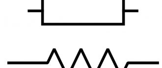
The resistor designations on the diagrams vary depending on the country. In our country, you can understand where the resistor is marked by a rectangle marked in the form of inclined or vertical lines, V or X signs, with the letter “R” at the top of the rectangle. On foreign (American) circuits, the resistor is indicated by a solid line with several breaks.
The figure below shows the resistor markings:
Slanted lines indicate resistor power up to 1 W. Vertical lines and V and X (Roman numerals) indicate the resistor's power of several watts, according to the Roman numeral value.
Real resistor
The following question reasonably arises: “What is a real resistor?” In life, this equipment, striving for the ideal, assumes the presence of only a few perfect qualities.
Depending on the type of equipment, the appropriate types of resistors are used. They perform strictly defined functions that will ensure proper operation in specific conditions.
To do this, resistor designers must either sacrifice the area that the equipment occupies on the circuit, or take into account environmental influences, as well as provide additional internal capacitances, etc.
Real resistors have a resistance different from that indicated on the case, which is due to the influence of different external conditions.
Variable resistor.
A variable resistor is a resistor in which the electrical resistance between the moving contact and the terminals of the resistive element can be changed mechanically.
Variable resistors, also called rheostats or potentiometers, are designed to gradually regulate current and voltage.
The difference is that a rheostat regulates the current in an electrical circuit, and a potentiometer regulates the voltage. On radio circuits, variable resistors are designated by a rectangle with an arrow attached to their body.
In the diagrams, numbers 1 to 3 indicate the location of the resistor outputs.
You can adjust the resistance power of variable resistors by rotating a special knob. Those resistors in which the resistance of the resistor can be adjusted only with a screwdriver or a special hex key are called tuning variable resistors. They look like this:
Marking: designation
For the vast majority of the element base, radio factories resort to special markings with a certain color, but sometimes they use both digital and letter designations. For example, SMD resistive elements have only letters.
Color markings are 4...6 stripes of different colors, which carry certain information. The first 2 digits indicate the nominal resistance, and the 3rd, by which the first 2 are multiplied, ultimately demonstrate the total resistance value. The 4th indicates the accuracy class of the resistor. If there are more stripes, then only the 1st indicator changes by one digit.
Thermistors, varistors and photoresistors.
In addition to rheostats and potentiometers, there are other types of resistors: thermistors, varistors and photoresistors. This is interesting, but thermistors, in turn, are divided into thermistors and posistors. A posistor is a thermistor whose resistance increases with increasing ambient temperature. With thermistors, on the contrary, the higher the temperature around, the lower the resistance. This property is referred to as TCR - thermal coefficient of resistance.
Depending on the TKS (it is negative or positive), thermistors are designated on the diagram as follows:
The next special class of resistors are varistors. They change the resistance force depending on the voltage applied to them. In the picture below you can see what varistors look like
Knowing the properties of a varistor, you can guess that such a resistor protects the electrical circuit from overvoltage. In the diagrams, varistors are designated as follows:
Depending on the light intensity, another type of resistor changes its resistance - photoresistors. Moreover, it does not matter what the source of lighting is: artificial or natural. Their peculiarity is also that the current flows in them both in one and in the other direction, that is, they also say that photoresistors do not have a pn junction. Photoresistors look like this:
And the diagrams look like this:
Today it is impossible to manufacture a single, somewhat functional electronic device without resistors. They are used everywhere: from computers to security systems.
Scope of application of resistors
The resistor plays a vital function in the operation of electrical systems. For example, it is able to control the distribution, power and other characteristics of electricity in a car. A resistor of any size located in the heating system allows you to precisely regulate the amount of heat supplied.
An element located in the LEDs allows you to adjust the lighting intensity. Consequently, this mechanism allows us to more accurately regulate the operating parameters of the equipment. Otherwise, we would have to use a pre-established mode of operation of the equipment without the possibility of changing it.
Symbols on diagrams
On diagrams in Europe and the CIS it is indicated by a rectangle and a Latin letter R. According to GOST, on domestic diagrams the resistance rating is not indicated, but only the part number (R). However, if there is a number below the part image, such as 120, it will default to read 120 ohms.
The table contains examples of part designations.
| Basic designation |
| 0.125 W |
| 0.25 W |
| 0.5 W |
| 1 W |
| 2 W |
| 5 W |
| Variable |
| Trimmer |
Technical designation
In radio-electronic circuits and technical documentation, the symbol of a resistor in the form of the Latin letter R is accepted, regardless of how it is designed. Next to the letter is the denomination of the element in accordance with the International System of Units (SI) and its serial number. For example, R21 150k means that the radio component has number 21 in the specification for the circuit, and its resistance value is 150 kilo-ohms.
Conventionally, the graphic designation is usually depicted according to GOST 2.728−74 ESKD. According to it, the resistor is depicted as a rectangle, from each middle of the side edges of which a straight line is drawn, indicating the output.
If it is necessary to additionally indicate the dissipation power of the element, then dashes or Roman numerals are placed in the middle of the rectangle. For example, a single slash represents a maximum allowable power dissipation of 0.25 W, while a Roman two represents 2 W. This designation of a resistor is accepted in Europe and the former USSR, while in the USA it is depicted as a broken line.
You might be interested in How the Hall effect is used: principles of the phenomenon and methods of application
In the case of an image of an adjustable resistor, an arrow is drawn on top indicating a moving contact. In addition, to emphasize the design features, the rectangle is crossed out with an inclined line, at the bottom of which a shelf is drawn. A letter is placed next to it, serving as a classifier of the element. For example, U is for a varistor, P is for a strain gauge.
On the resistor body itself, a alphanumeric code is affixed or colored stripes are drawn. This marking is needed so that you can determine what the resistor value is without resorting to measurements and diagrams.
The number in the code indicates the resistance in ohms, and the letter after it indicates the multiplier. In stripe designation, the principle is used that each color of the strip corresponds to its own order. For example, red is for two, green is for five. The first two stripes indicate the denomination, the third is the multiplier, and the fourth and fifth are the tolerance.
How to measure the resistance of a resistor
Any resistor has resistance. For those who don’t know what resistance is and how it is measured, read this article as a matter of urgency. Resistance is measured in Ohms. But how do we find out the resistance of the resistor? There are direct and indirect methods.
The direct method is the simplest. We need to take a multimeter and simply measure the resistance of the resistor. Let's take a look at what this all looks like. I take a multimeter, set the knob to measure resistance and touch the resistor terminals.
Resistance measurement
I took a 1 kOhm resistor. He showed me 976 Ohms, which in principle is also normal, since such resistors always have some error.
The indirect measurement method is that we will calculate the resistance of the resistor through Ohm's law.
resistance formula through Ohm's law
Therefore, to find out the resistance of the resistor, we need to divide the voltage at the ends of the resistor by the current that flows through the resistor. It's quite simple!
Let's say I want to know the resistance of a light bulb's filament when it emits light. I think some of you are aware that the resistance of a cold tungsten filament and a hot one are completely different resistances. I can’t measure a red-hot tungsten filament of an incandescent lamp with a multimeter in resistance measurement mode, right? Therefore, this formula comes in handy for us.
Let's find out by experience. I have a laboratory power supply that immediately shows the voltage and current that flows through the load. I take a lamp, set the voltage on the power supply, which is written on the lamp itself, and connect it to the terminals of the power supply.
Incandescent lamp current consumption
So, it turns out that the voltage at the lamp terminals is now 12 Volts, and the current that flows in the circuit, and therefore through the lamp, is 0.71 Ampere.
We find that the resistance of the hot filament of the lamp in this case is.
Selecting a resistor by resistance
Most people, when an electrical appliance fails, send it in for repair or replace it, although in many cases it is the resistor that is to blame, especially since it is one of the most common elements in any circuit. But there are also those who undertake repairs on their own.
And often DIY repair enthusiasts have a question about how to choose the right resistor for a particular circuit.
To do this, let's take the simplest circuit, including a power source and one consumer.
Even at the beginning, it was indicated that electricity has three main characteristics - voltage, current and resistance. It is based on these parameters that all the necessary calculations are made using Ohm’s law.
According to this law, since we need to determine resistance, we should divide the voltage by the current.
For example, our power supply provides a 12 V circuit with a current of 0.02 A.
To determine the resistance, we carry out mathematical calculations - 12/0.02 and get a circuit resistance of 600 Ohms.
Now directly about how to calculate the resistance of a resistor for use in a particular circuit. For example, let's take a 12 V power source and a consumer (3.5 V incandescent lamp, 0.28 A).
First, the lamp resistance is calculated - 3.5/0.28 = 12.5 Ohms. Now we find out how much current will flow through the existing lamp - to do this, take the voltage of the power source and divide by the resistance: 12/12.5 = 0.96 A, which is 3.5 times the current required for the consumer to operate, and if you connect consumer, then the lamp filament will simply burn out.
To prevent burnout from occurring, a resistance in the circuit of 43.75 Ohms (12.5 * 3.5) is required. And since the lamp itself creates resistance, an additional 30 Ohm resistor must be connected to the circuit. During the calculations, we get - 12 V / 42.5 Ohm (lamp and resistor resistance) = 0.28 A.
That is, we received the current strength necessary for normal operation of the consumer. In this case, the element included in the circuit acted as a current limiter.
Series and parallel connection of resistors
All of the above resistors can be connected in parallel or in series. In a parallel connection, the resistor leads are connected at common points.
In this case, to find out the total resistance of all resistors in the circuit, it will be enough to use the formula, where the resistance between points A and B (RAB) is the same R total:
When connected in series, the resistor values are simply summed up stupidly
In this case
Good video on the topic
Inclusion types and usage examples
The main types of connection are serial and parallel connections.
Series resistance is calculated simply. It's enough to put everything together.
In a series connection, the voltage is distributed across the resistors according to their resistances.
This is Kirchhoff's second rule. For example, the voltage is 12 V, and a pair of resistors are 1 kOhm each.
Accordingly, each of them has 6 V. This is a simple example of a voltage divider. Here a couple of parts share the voltage and through this the required voltage can be obtained.
However, if you want to use a voltage divider to power a circuit, you must remember that you need to match the resistances. In this circuit the resistance is 1 kOhm. If you connect a load less than this resistance to it, then it will not receive the full voltage at its terminals. Therefore, all circuits with voltage dividers must be calculated and coordinated with each other.
Let's look at the example of a transistor amplifier.
Here R1 and R2 form a voltage divider, they act as a voltage divider. A current flows between these two resistors and the base of the transistor, which turns on the transistor.
This is necessary for it to work without distortion.
Parallel connection
When connecting radio components in parallel, the overall resistance of the circuit decreases. If two 1 kOhm resistors are connected in parallel, then the total will be less than 0.5 kOhm, i.e. The circuit resistance (equivalent) is equal to half the smallest.
In such a connection, Kirchhoff's first rule is observed. A current of 1 A is sent to the connection point, and at the node it diverges into two directions of 0.5 A each.
Calculation formulas
For two resistors:
For more:
For current, a parallel connection is like a second road or bypass. This type of connection is also called bypassing. An example is an ammeter. To increase its reading scale, it is enough to connect another shunt resistor in parallel with the resistor.
Its resistance is calculated by the formula:
Equivalent connection
In the amplifier circuit, a pair of resistor R3 and capacitor C2 is connected to the emitter of transistor VT1.
In this case, VT1 and R3 are connected in series to each other. Why is this necessary? When the amplifier is running, the transistor begins to heat up and its resistance decreases. R3, as in the case of the LED, prevents the transistor from overheating. It balances the total resistance so that the transistor does not distort the signal. This is called thermal stabilization mode.
And capacitor C2 is connected to R3 in parallel. And this is necessary so that during normal operation of the amplifier, the alternating signal passes through without loss. This is how a parallel filter works.
If there was only one R3, then the amplifier's power would be much less due to the fact that it takes the AC voltage onto itself. A capacitor transmits without loss, but does not transmit DC voltage.