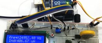
How to use the DT 838 multimeter
A multimeter, or as it is also called a “multitester,” is a combined measuring device that allows you to measure alternating and direct voltage, electric current, resistance, and also perform a number of other useful functions.
For example, many modern multimeters can test diodes and measure the gain of transistors, test a cable or circuit for a short circuit, and much more.
More expensive models of multimeters (including DT 838), even allow you to take temperature readings from something (using a special thermocouple probe), check the capacitance of a capacitor, etc. However, before using a multimeter, you should find out , what's what, and understand what you want to measure with this electronic device.
Features of the device
The DT-838 multimeter (or tester, as it is popularly called) allows you to perform a number of measurements:
- Definition of alternating current.
- DC current measurement.
- Determination of current strength.
- Resistance measurement.
- Temperature detection (an additional sensor is required, which is purchased separately).
- Carry out sound testing of wires.
The device operates in a wide temperature range (from 0 to plus 40 degrees). The DT-838 multimeter displays measurement results on a liquid crystal display. Moreover, the device measures indicators not once, but several times. From 3-4 readings, the device calculates the average value, which is reflected on the indicator.
The multimeter runs on a 9-volt battery. It is included in the delivery kit (most often already installed in the device). When determining voltage or current, the device is able to automatically determine polarity. It is recommended to follow them. If the polarities are violated, the value will be displayed with a minus sign.
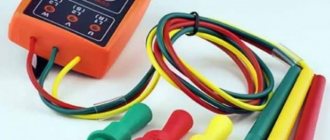
In addition to the battery, the kit includes:
- Tester.
- Thermocouple.
- Probes.
When measuring, it is very important to connect the probes correctly. To determine the current strength, the probes are connected in series with the load. To determine other parameters, the probes are connected in series.
Overview of some types of multimeters
Nowadays you can find a wide variety of multimeters with many functions. But the main and popular device is a digital multimeter with a small number of functions, such as the DT-838. A small number of types of measurements is quite sufficient even for professional electricians.
Analog and digital multimeters
Functions such as measuring the transmission coefficient of transistors and generators are not needed for the work of an electrician. The main measurement functions for an electrician are measuring direct and alternating voltage, measuring direct current, resistance, checking diodes, and sound continuity.
Digital multimeters have an easy-to-read seven-segment display. Such devices have only manual selection of measurement limits. You need to work with them carefully and correctly select the limits for measuring voltage and current, otherwise you can easily burn the device.
There are also automatic digital multimeters that are more convenient to work with. On such a device, only the type of measurement of voltage, direct and alternating current, and resistance is selected. The measurement limits are determined automatically, starting with the largest. The likelihood of burning such a device is minimal. Unless you confuse the type of measurement. For example, after measuring resistance, without switching the type of measurement, start measuring the voltage in the socket.
Automatic multimeter XB-868
No device can withstand such an error. Therefore, when measuring with any tester, be careful and choose the limits and types of measurements correctly. One example of an automatic multimeter is the XB-868 device. In addition to the usual types of measurements, it has automatic power off after 15 minutes of inactivity, capacitance measurement, and a frequency meter.
Analog testers include dial gauges. The Chinese version of such a YX tester is 360TR. Pointer instruments are much simpler than digital devices and therefore much more reliable. These devices have almost the same functions as digital ones. It is believed that the display of digital multimeters is more convenient. The readings on it are easy to read. However, the dial gauge scale is not as complicated as it seems.
Pointer analog tester YX 360TR
If you use this tester often, then the readability of the scale will also be convenient. You just need to understand the structure of the scale and start working with the device. For example, the upper resistance scale is used for all resistance measurement limits. It shows the resistance in ohms from 0 to 1000 ohms at the X1 limit. At the X10 limit, the readings are multiplied by 10 and so on.
Also, the voltage scale is from 0 to 250 V. At the limit of 1000 V, the scale readings are multiplied by 4. Everything is quite simple. This device has a manual calibration of the resistance scale at a given limit. Pointer testers have the advantage that resistance is measured at currents of several tens of milliamps.
With this current, the readings are not affected by electromagnetic interference, unlike digital devices, and oxide easily breaks through on the terminals of the measured elements and wires. The readings from pointer instruments will be more reliable. The continuity of power diodes will also be more reliable. The currents of digital multimeters when measuring resistances and diodes are only a few microamps, which may not be enough to break down conductor oxide and dirt.
Reliable tester Ts4353 from Soviet times with an error of 1.5%
Soviet pointer testers, such as the Ts 4353, were very reliable. They are still considered the best pointer measuring instruments. These devices have voltage protection when the measurement limit is incorrectly selected. The accuracy of their measurements reaches 1.5%, which is still considered a high figure.
Working with the device
The DT-838 multimeter is easy to use. But there are situations when, after purchasing a device, people do not know how to use it. There is nothing complicated here.
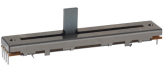
The range switch is set to the desired mode. To do this, you must select one from the given values. The switch itself can be rotated in both directions (both clockwise and counterclockwise). One of the probes is always located in the “COM” hole. For direct current it should be “minus”. The second probe is always installed in the VOMA hole. An exception is the determination of current strength.
Functions performed by the device
The word “multimeter” itself consists of two words: “multi” means “many”, and “meter” means “to measure”. It turns out that using the device you can make many different measurements. The first devices were point devices. The arrow rotated along the scale using an electromagnet, and a spring returned it back. Modern devices have mostly completely switched to digital display. What can they measure? To understand how to use the DT 838 multimeter, it is important to know its features.
Constant pressure
The presence of electric current is difficult to determine without a device. You can, of course, touch it with your hand if you know that the voltage is small, but how do you know what it is? Existing indicators only indicate the presence of life-threatening voltage. It is measured between two points and shows the potential difference if there is no external influence. The circuits in which the measurements are made are divided into two types:
- D.C.
- Alternating current.
Constant is a current whose magnitude and direction do not change over time. An example would be a battery.
Variable current is a current that changes its magnitude and (or) direction over time . This includes:
- sinusoidal;
- intermittent;
- rectified.
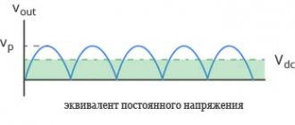
In practice, alternating voltage means a sinusoidal current that changes its polarity. It is also called periodic because the polarity changes regularly at regular intervals. Measuring DC voltage is not difficult, since the value remains unchanged over time.
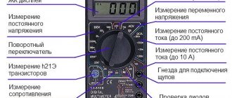
On the panel of the DT 838 multimeter itself, in the upper left corner there is a letter V, next to which a straight and broken line is drawn. The polygon outlined in white contains numbers. This is a scale for measuring DC voltage, where the maximum values of the measured voltage are indicated. If there is a letter m next to the number, then millivolts are measured. 1 volt contains 1000 mB. To connect the required value, the marked end of the multimeter handle is aligned with the selected number.
Effective value
The DT 838 digital multimeter comes with probes with wires of different colors. Black connects to the bottom socket, red to the middle one. These sockets on the instrument panel are graphically connected, and the inscription present shows the limits of the measured current and voltage. The indicators allow you to measure direct and alternating voltage up to 600 V, and current up to 200 mA.
Alternating (sinusoidal) voltage constantly changes over time, and this presents a certain difficulty. If we take the average value, it will be equal to zero, obtained by adding the maximum “plus” with the maximum “minus”. Therefore, different measurement methods are used:
- instant;
- amplitude;
- valid.
The instantaneous value shows the voltage at a certain time, and the amplitude value determines the maximum value. These methods are rarely used, because they mainly reveal the effective voltage. To do this, compare the work of alternating and direct current, dividing the amplitude value by the root of two (approximately 1.41). Knowing the effective value, you can determine the amplitude. For example, if the network is 220 V (rms value), then the amplitude will be equal to 311 V.
Technically, this happens as follows: two diodes connected in series are connected in parallel with the same other two diodes. An alternating voltage is connected between two series-connected diodes, the positive voltage is removed from the combined cathodes, and the negative voltage is removed from the anodes. Thus, the alternating voltage is converted into direct voltage and then measured. To extinguish its excess, a resistor is connected in series.
By turning the switch lever, one or another resistor is connected, expanding the capabilities of the device. If the measured voltage is unknown, the measurement always starts with a higher value. It is strictly forbidden to find and use voltage exceeding the maximum permissible for the device.
Current measurement
Unlike measuring voltage, when a voltmeter is connected in parallel with the power source, current is measured differently. The electrical circuit being measured is broken, and an ammeter is connected to the gap. In this case, the multimeter introduces its own resistance. To reduce distortion and expand the measurement limit, shunts are used - resistors with a very precisely selected resistance, which are connected in parallel to the device and reduce the total resistance.
In a multimeter, such a shunt allows you to measure significant currents , because its resistance is less than the resistance of the measuring device, and the bulk of the current passes through it. It dissipates a very large current, so some multimeters have a warning on the panel about how long it can take to measure large currents. For example, DT 838 C states that measuring a current of 10 A should last no more than 10 seconds with 15 minutes of rest.
In the DT 838 multimeter, the measured current can reach up to 10 A. In this case, the probe with a red wire is connected to the upper contact (it serves only for this purpose), and the switch position is set to 10 A. The scale for measuring current is indicated by the letter A with a straight line and broken lines. Small currents are measured in milliamps (with the letter “m”) or microamps. 1A = 1000 mA = 1 million microamps.
It is strictly forbidden to connect the ammeter according to the voltmeter circuit, i.e. in parallel with the power source. The device is designed to measure direct or unidirectional current only. This is due to the fact that diodes are needed to rectify the current, and they have a very high forward resistance, which is unacceptable for an ammeter. To measure alternating current, special transformers are used.
Definition of resistance
The third basic quantity of electric current is resistance. It is measured relative to direct current. For this purpose, the device uses a battery. You can also use a battery, but this is undesirable, since the energy consumption is small and the battery will lose capacity. The readings are given in Ohms, and if the number is followed by the letter “K” - in kilo-ohms.
To check the resistor resistance, set the device switch to the mark that most closely matches the resistor value. On the device this scale is o. When checking variable resistors, measurements are taken both overall and between the moving contact and one of the extreme ones. Moreover, when the moving contact is turned, the resistance should change smoothly. This measurement shows the quality of the moving contact.
If the resistor is on the board, then one of its terminals must be unsoldered (variable, perhaps completely), otherwise the reading may be inaccurate. An ohmmeter can be used to check not only resistors, but also almost all other radio components. For example, you can check for a short circuit (short circuit) of the motor winding on the housing. The operating condition of semiconductor devices, capacitors and other elements can be checked by knowing how they work.
Voltage detection
To carry out any measurement, you first need to turn the switch equipped with the DT-838 multimeter to the desired mode. The instructions will help you understand which designation corresponds to the required mode.
When choosing the desired mode, you must remember that there is direct current in batteries, accumulators, and power supplies. On the device it is designated DCV and is located on the left. For example, when determining the DC voltage of a battery, it is enough to set the mode to twenty volts.
AC power is found in outlets. It is designated on the device as “AC”.
The red probe must be installed in socket 10ADC. As a rule, it is the top nest.
Features of digital multimeters
The operation of the device is based on an analog-to-digital converter, where the incoming analog signal is converted into a digital code for further processing by a controller chip. To read parameters, you need to connect wires (probes) to the circuit or its components. The black probe is negative or common, the red probe is positive.
To understand how to use a multimeter correctly, familiarize yourself with the main symbols on the panel:
- off — the device is turned off;
- avc is an indicator of alternating voltage;
- dvc - constant voltage;
- dca—direct current;
- Ω is resistance.
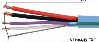
Any modern multimeter has three connectors for connecting wires. It is necessary to connect the wires correctly so as not to damage the device and correctly read the data:
- the black wire is connected only to the COM input;
- if necessary, measure current up to 200 mA or resistance, plug the red wire into the “VΩmA” connector;
- if the current is more than 200 mA, then the red cord is connected to “10ADC”.
To remove individual parameters, you use your own connection and adjustment diagram for the device. To fully understand all the features of the tester, below is a step-by-step instruction in the style of “how to use a multimeter for dummies.”
Detecting a short circuit in a circuit
The multitester is used in different ways for different purposes. Let's look at an example of how to use the DT838 multimeter to detect a short circuit (hereinafter referred to as a short circuit) in a circuit. This is a universal model that is often used by radio amateurs at home. It runs on a 9 V Krona battery. In addition to standard functions, this device has sound signals for continuity and the ability to measure temperature.
To determine the presence of a short circuit, follow the instructions:
- Turn on the multimeter and insert the probes into the corresponding connectors (COM - black and VΩmA - red).
- Switch the “handle” to dialing mode.
- Touch the probe to one end of the circuit, and the other to the other. If there is a short circuit, a squeaking signal will be heard.
So quickly and easily you will find out about the presence of a short circuit.
How is direct current measured?
Let's look at how to measure the DC current in a battery using the DT182 multimeter model as an example. This is a compact device that is used in everyday life, with a measurement speed of 2-3 times per second. They can also test the circuit for short circuits and perform all other basic measurements.
To find out whether the battery is charged or not, do the following:
- Turn on the DT182 multimeter and install the probes in the correct position (as in the previous example for determining a short circuit).
- Set the “knob” to the maximum value of 500 V.
- Attach the free end of the black probe to the non-insulated part of the battery.
- Place the red probe on the measurement point, for example, on the “+” battery.
- If during the measurement process the display shows numbers from 12 to 14.6 V, then the battery is charged.
Tip: to increase the measurement accuracy, you can set the switch to 20 V, but not lower than this value.
Checking the outlet or measuring AC voltage
In addition to determining the battery charge or the presence of a short circuit, a multimeter is often used to check the functionality of the outlet. Let's consider this action using the compact tester model DT9205A as an example. Its features include high measurement accuracy, but the lack of temperature measurement functions and a thermocouple are missing.
To check the voltage at an outlet, do the following with your DT9205A multimeter:
- Place the probes in the corresponding sockets “COM” and “VΩmA”, and turn the control knob to ACV (750 V).
- Plug the probes into the socket one at a time, and it doesn’t matter which one you insert where.
- If a value within 200–220 V appears on the screen, this is considered a good indicator.
This method is used to check household sockets for their functionality. Even a non-professional can master this technique with a DT9205A digital multimeter in his hands.
Important! Each device comes with detailed operating instructions, where you can find answers to all your questions.
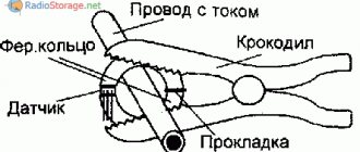
Features of checking the thermocouple
A thermocouple is a sensor consisting of two dissimilar conductors having several contacts with each other. It works on the principle of voltage generation by these conductors due to temperature changes in any part of the sensor.
So, how to check a thermocouple with a tester if the button on the gas boiler box does not lock during operation. To identify such a malfunction, do the following:
- Turn off the boiler completely, cutting off the supply of gas and electricity. This is necessary for safe operation.
- The thermocouple is located between the temperature sensor and the nut with which it is attached to the valve.
- It is necessary to remove the thermocouple by unscrewing the nut.
- Heat the sensor over an open, constant flame, for example, over a burner that is on. At the same time, keep the device at a distance of 10 mm from the flame. Wear gloves first to avoid getting burned.
- Set your multimeter to mV. Then, attach one probe to the thermocouple body, the other to the output contact.
- Within a minute after heating, the device will detect the presence of voltage. The tester screen should display a number from 18 to 25 mV, which indicates that the thermocouple is working.
Additional features
The DT-838 multimeter allows you to measure temperature. To do this, change the position of the switch to the desired mode. A thermocouple is connected instead of probes. The tip of the pendant is connected to the object whose temperature needs to be determined. In this case, a thermocouple is needed to measure the temperature of the object. Without it, the device will show its internal temperature. It is usually at the same level as the room temperature. This function allows you to control the heating (or overheating) of any radio components or microcircuits.
Dialing connections is easy. This is necessary to determine the location of the network break (if the wiring is broken). Another possibility is to detect an emerging short circuit. To start measuring, turn the switch to the required position. Next, use two probes to touch different ends. If a short circuit occurs, a beep will sound.