Schematic diagram and design of homemade current clamps for measuring current, attachment to a multimeter.
To measure large currents, they usually use a non-contact method - special “current clamps”. Let me remind you that this is an electronic measuring device, like a multimeter, which has a kind of clothespin sticking out from the top.
This clothespin is attached to a wire and the current readings in this wire appear on the digital display. The advantages of this method are obvious - in order to measure the current strength, you do not need to break the circuit, which is especially important when measuring large currents.
Homemade current (current) clamps on a Hall sensor, attachment to a multimeter
Schematic diagram and design of homemade current clamps for measuring current, attachment to a multimeter.
To measure large currents, they usually use a non-contact method - special “current clamps”. Let me remind you that this is an electronic measuring device, like a multimeter, which has a kind of clothespin sticking out from the top.
This clothespin is attached to a wire and the current readings in this wire appear on the digital display. The advantages of this method are obvious - in order to measure the current strength, you do not need to break the circuit, which is especially important when measuring large currents.
How to use a clamp meter
Current flowing through a single conductor
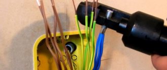
When measuring the current flowing through one conductor
, you must select the measurement mode by setting the switch to the required position, and connect the current clamp to the conductor being measured. If necessary, this must be done using the magnetic circuit release button.
If the current clamp displays the number “1” on the information screen, you should change the position of the mode switch to a higher value.
Current flowing through several conductors
When simultaneously measuring the current flowing through several conductors
(for example, a power cable), several conductors need to be inserted into the magnetic circuit of the current clamp. In this case, the device will measure the difference in current flowing through the conductors. That is, if you take measurements in a single-phase network, in which there are only “phase” and “neutral” wires, then the device will measure the leakage current in the load.
Voltage measurement
To measure the voltage, you need to connect the red wire of the probe to the connector for connecting probes - “VΩ”, the black wire of the probe to the connector - “COM”. Then use the switch to select the mode according to the measured range.
The probes must be connected to a voltage source. The device screen will display the polarity and measured voltage.
Resistance measurement
When measuring resistance, the probes are connected to the current clamps in the same way as in the case of measuring voltage
. The switch must be set to the “Ω” position. If the resistance of the section of the circuit where the measurement is being made is less than 50 Ohms, the device will signal with an audible signal.
Design
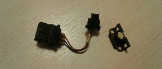
You can make a “current clamp” for a regular multimeter yourself if you have a sensitive Hall sensor, for example, UGN3503. Figure 1 shows the design of a homemade “pincer”.
You need, as already mentioned, a hall sensor, as well as a ferrite ring with a diameter of 20-25 mm and a large “crocodile”, for example, to connect something to a car battery.
The ring must be accurately and accurately broken into two halves. To do this, the ring must first be filed with a medical file for ampoules. Then, treat the broken surfaces with fine sandpaper. On one side, stick a thick paper gasket (drawing paper) onto one of the halves of the ring. On the other side, stick a Hall sensor onto one of the halves of the ring.
It is most convenient to glue with epoxy glue, but so that the sensor fits tightly to the place where the ring breaks. Then, folding both halves of the ring as shown in Figure 1, they need to be inserted into the “crocodile’s mouth” and glued to the “crocodile’s jaws” with the same epoxy glue.
The result should be a structure schematically shown in Figure 1. When pressing on the “crocodile” handles, the ferrite ring should open along with its “jaws”.
Rice. 1. Design of homemade current measuring (current) clamps.
Schematic diagram
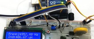
Now from the electronic part. The schematic diagram of the multimeter attachment is shown in Figure 2. When current passes through a wire, a magnetic field appears around it, the lines of force of which penetrate the Hall sensor, and some constant voltage appears at its output.
This voltage is amplified in power by operational amplifier A1 and supplied to the input of the multimeter. Dependence of output voltage on current: 1A = 1 mV. Trimmer resistors R3 and R6 must be multi-turn.
Rice. 2. Schematic diagram of homemade current measuring (current) clamps.
Setting up
To set up, you need a laboratory power supply with an output current of at least 3A, with a built-in ammeter.
First, connect the attachment to the multimeter and calibrate it to zero by adjusting R3 with R2 in the middle position. Then, before each measurement, you will need to set zero with the variable resistor R2.
Set the source to the minimum voltage and connect a powerful load to it, for example, a lamp from a car headlight.
Attach a “clamp” to one of the wires going to this lamp (as shown in Figure 1). Increase the voltage until the source ammeter shows 2-2.5K.
Adjust R6 so that the multimeter reading in millivolts is equal to the source ammeter reading in amperes. Check the readings by changing the current in one direction or the other (decreasing - increasing the current and comparing with the source ammeter).
Using this attachment you can measure current up to 500A. For example, you can measure the current consumption of a car starter at the moment the engine starts.
Source
DC current clamp - do-it-yourself multimeter attachment. Description
To measure large currents, as a rule, a non-contact method is used - special current clamps. Current clamp is a measuring device that has a sliding ring that covers an electrical wire and the amount of current flowing is displayed on the device indicator.
The superiority of this method is undeniable - in order to measure the current strength there is no need to break the wire, which is especially important when measuring large currents. This article describes a DC current clamp , which is quite possible to make with your own hands.
Advantages and some features
The main advantages of use are:
- the ability to measure current under conditions of continuity of the measured circuit;
- fairly simple measurement in particularly high-voltage systems, up to 10 kV;
- compact dimensions of the device;
- possibility of measuring alternating and direct currents.
But, as with any devices, current clamps have features that are sometimes considered disadvantages, although at the current level of technical development any design problems are solved by introducing additional electrical circuits. These features include:
- relatively low accuracy class (usually 2.5);
- dependence of the final indicators on the position of the clamps on the measured wire;
- strict dependence on the measured current (sinusoidal only).
Description of the design of homemade current clamps
To assemble the device you will need a sensitive Hall sensor, for example, UGN3503. Figure 1 shows the device of a homemade pliers. You need, as already mentioned, a Hall sensor, as well as a ferrite ring with a diameter of 20 to 25 mm and a large “crocodile”, for example, similar to the one on the wires for starting (lighting) a car.
The ferrite ring must be accurately and accurately sawed or broken into two halves. To do this, the ferrite ring must first be filed with a diamond file or an ampoule file. Next, sand the fracture surfaces with fine sandpaper.
On one side, glue a gasket from drawing paper to the first half of the ferrite ring. On the other side, stick a Hall sensor on the other half of the ring. It is best to glue it with epoxy glue, you just need to make sure that the Hall sensor is in good contact with the fracture zone of the ring.
The next step is to connect both halves of the ring and wrap it around it with a crocodile and glue it. Now, when you press the crocodile handles, the ferrite ring will diverge.
Electronic circuit of current clamps
The schematic electrical diagram of the multimeter attachment is shown in Figure 2. When current flows through an electrical wire, a magnetic field appears around it, and the Hall sensor detects the power lines passing through it and generates some constant voltage at the output.
This voltage is amplified (by power) by op amp A1 and goes to the multimeter terminals. The ratio of the output voltage to the flowing current: 1 Ampere = 1 mVolt. Trimmer resistances R3 and R6 are multi-turn. To set up, you need a laboratory power supply with a minimum output current of about 3A, and a built-in ammeter.
First, connect this attachment to the multimeter and set it to zero by changing the resistance R3 and the middle position of R2. Next, before any measurement it will be necessary to set zero with potentiometer R2. Set the power supply to the lowest voltage and connect a large load to it, for example, an electric lamp used in car headlights. Then hook the “pliers” onto one of the wires connected to this lamp (Figure 1).
Increase the voltage until the power supply ammeter shows 2 amperes. Tighten resistance R6 so that the voltage value of the multimeter (in millivolts) matches the data on the power supply ammeter in amperes. Check the readings a few more times, changing the current strength. Using this attachment it is possible to measure current up to 500A.
Source
DC current clamp - do-it-yourself multimeter attachment. Description
To measure large currents, as a rule, a non-contact method is used - special current clamps. Current clamp is a measuring device that has a sliding ring that covers an electrical wire and the amount of current flowing is displayed on the device indicator.
The superiority of this method is undeniable - in order to measure the current strength there is no need to break the wire, which is especially important when measuring large currents. This article describes a DC current clamp , which is quite possible to make with your own hands.
Description of the design of homemade current clamps
To assemble the device you will need a sensitive Hall sensor, for example, UGN3503. Figure 1 shows the device of a homemade pliers. You need, as already mentioned, a Hall sensor, as well as a ferrite ring with a diameter of 20 to 25 mm and a large “crocodile”, for example, similar to the one on the wires for starting (lighting) a car.
ElektroMaster.org DIY repair and maintenance of household electrical appliancesTips, guides..
Yandex.Direct
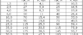
Ammeter is a device for measuring current in amperes. The scale of ammeters is calibrated in microamperes, milliamperes, amperes or kiloamperes in accordance with the measurement limits of the device.
In an electrical circuit, the ammeter is connected in series with the section of the electrical circuit in which the current is measured; to increase the measurement limit - with a shunt or through a transformer.
(An example of an ammeter with a transformer is a "current clamp"
Current clamp - Ammeter for non-contact measurement of large currents, allows you to measure current strength in a non-contact way with high accuracy, without interrupting the power supply to consumers.
When measuring current, the clamp probes, in which ferrite cores are mounted, seem to wrap around the conductor, remaining completely isolated from open sections of the wires.
Due to the formation of an oscillatory circuit by ferrites when current flows through the conductor, magnetic induction occurs, the value of which is directly proportional to the current flowing through the conductor.
This value is recorded by the current sensors of the current clamps and is converted into a current value, which is either displayed on the display of the current clamps (if it is designed) or outputs the value to an external multimeter through remote probes. Depending on the modification, current clamps can measure the strength of both direct current and alternating current.
general characteristics
The most common ammeters are those in which the moving part of the device with the pointer rotates through an angle proportional to the magnitude of the current being measured.
Ammeters are magnetoelectric, electromagnetic, electrodynamic, thermal, induction, detector, thermoelectric and photoelectric.
Magnetoelectric ammeters measure direct current; induction and detector - alternating current; ammeters of other systems measure the strength of any current. The most accurate and sensitive are magnetoelectric and electrodynamic ammeters. Operating principle
The principle of operation of a magnetoelectric device is based on the creation of torque due to the interaction between the field of a permanent magnet and the current that passes through the winding of the frame. An arrow is connected to the frame, which moves along the scale. The angle of rotation of the arrow is proportional to the current strength.
Electrodynamic ammeters consist of fixed and moving coils connected in parallel or in series. The interaction between the currents that pass through the coils causes deflections of the moving coil and the arrow connected to it. In an electrical circuit, the ammeter is connected in series with the load, and at high voltages or high currents - through a transformer.
The material partially uses information from wikipedia.org
Measurement modes
Mode switch
measurements, depending on the tasks, can be set to the following positions:
- alternating voltage – ACV;
- constant voltage - DCV;
- direct current – DCA;
- alternating current - ACA;
- resistance - Ω;
- dialing with sound signal;
- diode check.
The connectors for connecting the probes are marked with color and symbol. The black wire of the probes is connected to the black connector marked “COM”, the red wire of the probe is connected to the red connector marked “VΩ”.
The remaining red connector, labeled “EXT,” is required to connect the insulation meter.
How current clamps work and work and how to use them correctly
To diagnose faults in electrical equipment or electrical installations, it is often necessary to measure currents. There are two options: use an ammeter or using a current clamp.
The first option can be done using a regular multimeter, but it is bad because you need to break the circuit, and this is not always possible and not always convenient for making correct measurements.
The second method, clamp meters, allows you to find out the current in the circuit without disconnecting it. In this article we will look at how to use current clamps and how they work.
The operating principle of current clamps is based on the phenomenon of electromagnetic induction. The conductor in which the current is measured is inserted into the magnet and the wire on which the secondary winding is wound.
The measured current in this case is called primary, and the current in the measuring coil (secondary winding) is called secondary. Moreover, its value is proportional to the primary current and can be calculated.
The magnetic circuit of the clamps consists of two parts, one of which is movable; this design is needed in order to open the magnetic circuit using a lever and insert a conductor for measurements.
Current transformers work similarly, but their magnetic core is solid and is placed on a busbar or cable core.
Previously, clamp meters, for the most part, could only measure alternating current, since EMF on a winding can only occur under the condition of an alternating magnetic flux created by an alternating electric current.
Most modern, even the cheapest models, are capable of measuring both direct and alternating currents. DC current measurement is made possible by using a Hall sensor.
It also supports functions standard for multimeters - measuring resistance, voltage, frequency, continuity of circuits, and sometimes it is possible to connect a thermocouple to determine temperatures.
So, a current clamp consists of:
1. Composite moving magnetic circuit.
2. The main part of the housing with a display, a selector for selecting limits or selecting a measured value (if the limits are selected automatically), as well as connectors for connecting probes, for working in Ohmmeter, continuity or voltmeter mode.
3. Inside the case there is a board with microcircuits, sometimes with variable resistors for fine-tuning the measurement accuracy.
To measure current in hard-to-reach places, some clamps are equipped with an additional meter with a flexible sensing element. An example is a product from Fluke; it can be included in a kit or sold separately.
Current clamps. Device and types. How to choose
Current clamps are used to measure the electrical parameters of a power circuit in the form of phase angle, power, voltage or current, without disrupting the functioning of the circuit or breaking it.
Current clamp meters, which are clamp-on ammeters for measuring alternating current, have become very popular. They are designed for prompt measurement of current in a wire without taking it out of service and without breaking the circuit. Electrical clamps are used in electrical installations up to 10,000 volts.
Design and operation
A simple clamp meter model operates on the principle of a single turn current transformer. Its primary winding is the wire or bus being measured. The secondary winding, which has many turns, and is connected to the ammeter, is made on a split core.
a) – simple clamps using a 1-turn transformer. b) – clamps with a rectifier and a 1-turn transformer.
- Measured wire.
- Split core.
- Secondary winding.
- Rectifier.
- Measuring frame.
- Shunt resistance.
- Mode switch.
- Lever arm.
Clamp meters consist of three main elements:
- Working part: measuring device, transformer windings, magnetic circuit.
- Insulating part: from the handle stop to the working part.
- Handles: from the edge of the pliers to the stop.
To enclose the conductor being measured, the magnetic core can be opened by analogy with simple pliers, when hand force is applied to the insulated handles of the pliers.
Alternating current flows through the measured conductor, which is covered by a detachable magnetic circuit. In this case, the current forms a magnetic flux in the magnetic circuit, which creates an electromotive force in the secondary winding of the measuring clamp. When exposed to EMF, a current appears in the secondary winding, measured by an ammeter located in the measuring clamp.
Modern measuring devices operate according to a circuit that includes a current transformer with a rectification bridge. In this case, the output of the secondary winding is connected to an electrical measuring device using a set of shunts.
Varieties
Current clamps are divided into two types according to operating voltage and device:
- In electrical installations up to 1 kV, one-handed .
- In electrical installations 2-10 kV, two-handed .
One-handed electrical clamps combine a handle with an insulating part in their design. The magnetic core is opened using a special pressure lever. One-handed measuring clamps up to 1 kV can be of various sizes, and do not have specific size standards. You can use these pliers with one hand.
Two-handed measuring clamps for electrical installations from 2 to 10,000 volts have an insulated part size of at least 38 cm, handles over 13 cm. The design of such clamps allows for using the clamps with two hands.
According to the type of indicator, current clamps are divided into:
- Analog . They have a pointer display with a scale.
- Digital . Equipped with a liquid crystal screen.
Pointer ( analog ) measuring devices have not yet lost their popularity, despite the widespread use of digital instruments. Their advantage over digital devices is that they do not require a power source to operate.
To measure the starting current, it is much more convenient to use analog clamps, since they respond very quickly to a sudden change in the value of the electric current. In terms of the convenience of issuing measurement results, analog clamps are much inferior to digital devices, since the measured value can only be determined using a graduated scale.
Digital measuring devices are most convenient to use, since the measurement results are shown on the screen in digital form. Their disadvantage is the need for an auxiliary power source in the form of rechargeable batteries or batteries, as well as an increase in measurement error when the power source is discharged and electromagnetic interference.
According to the type of circuit parameter being measured, electrical clamps are divided into:
- Phase meters.
- Wattmeters.
- Ampere-voltmeters.
- Ammeters.
- Megaohmmeters.
Phase meters are devices that can measure the phase shift angle in a three-phase electrical network during operation of electrical equipment. In other words, this parameter is called power factor. Phase meters can be digital or electrodynamic.
Wattmeters , made in the form of measuring clamps, are used to measure the parameters of 3-phase and 1-phase networks in a non-contact way: reactive and active power. Most often, such devices are made in the form of a universal device that allows you to measure other parameters.
Ampere-voltmeters and ammeters in the device of electrical clamps function similarly to other types of clamps. They measure parameters of current, voltage in a certain circuit, or several parameters simultaneously.
Current clamps. Current clamp measurement
Current clamps are a convenient tool for measuring current at home and in enterprises. The functionality of such devices is ensured by applying the principle. Let's look at the structure of these devices, the features of their operation and methods of application.
Purpose
Current clamps make it possible to measure the performance of direct current or without de-energizing the conductors. As a result, it becomes possible to control the current consumption and carry out the necessary installation work while the equipment is operating. This feature makes current clamps second in demand in the arsenal of electricians, immediately after the multimeter.
Design
Standard DC current clamps have the following structure:
- Magnetic terminals.
- Holder release button.
- Switch for current measurement method.
- Display.
- Probe connection elements.
- System for recording indicators in the device memory.
Features of operation
Using the device is quite simple. To begin with, the switches are set to the required position. The pliers grasp the contacts, after which the indicators are recorded.
The main difficulty in operating the device is the need to separate a separate electrical conductor. Gripping the wire with the clamps along with the zero and phase leads to a total current that flows through all the wires.
By using current clamps to hold the entire cable, ideally the electrician gets a zero reading. If, with this connection method, the device shows different values, this may indicate a leak in the circuit.
In any case, for proper operation of the measuring unit and obtaining adequate indicators, it is necessary to find a place where it is possible to separate the individual electrical conductors. Sometimes all you need to do is look into the switchboard.
Unfortunately, it is not possible to take measurements with current clamps everywhere, which is an obvious disadvantage of the device. However, this drawback is completely covered by the ability to perform measurements without breaking the circuit.
How to use current clamps: instructions
The measuring device is connected to the electrical conductor in the following sequence:
- A place is selected where it is possible for the pliers to freely grasp a single cable.
- The mode switch knob is moved to the required position. For AC networks the designation “A” is used
" With constant current, the “A-” indicator is selected. The corresponding data, indicating the choice of one mode or another, is duplicated on the display.
- The pliers opening button is pressed, after which the grips are installed perpendicular to the conductor.
- The release device is released, which closes the circuit.
- The obtained values are recorded on the display. If necessary, data can be written to the device memory.
Security measures
In order for the measurement with current clamps to take place without negative consequences both for the condition of the circuit of conductors or an electrical device, and for the health of the user, it is necessary to pay attention to some precautionary requirements.
During measurements, electrical measuring grips must be kept suspended. It is not recommended to bend over or touch the pliers while taking readings. The presence of special electrostatic gloves is welcome.
When working with electrical installations with a power of up to 10 kW, the use of remote devices or switching measurement limits with connected contacts is prohibited. To change the value, you must remove the clamps from the conductors.
You should not use current clamps on overhead line supports with voltages up to 1000 V. If there is such a need, devices specially designed for these purposes are used.
Areas of application
With the help of current clamps it becomes possible:
- Determination of the actual load on the network. To measure the indicator in single-phase networks, measurements are taken on the input wire. The obtained data in amperes is multiplied by the voltage in the electrical network and the cosine of the interphase angle.
- Measuring the power of individual electrical appliances. When such a need arises, the current strength in sections of the circuit is determined without the need to disconnect the energy consumer. The power indicator is also calculated according to the above formula.
- Checking the functionality of devices designed to measure electrical energy consumption, checking meter values with objective, actual consumption.
How to choose current clamps?
When choosing an effective means for measuring the required parameters in conductors without breaking the electrical circuit, you should determine the necessary functionality and capabilities of the device. This is, first of all, fixation of indicators of a variable or
The specific shape of the device plays a certain role. The range of operating frequencies, the accuracy of measuring indicators, and the availability of necessary and additional functionality are also important.
In general, choosing a truly useful unit allows you to compare your own financial capabilities with the tasks to be performed.
Tools
0 votes
+
Vote for!
—
Vote against!
If you need to measure current without disconnecting the electrical network, using current clamps is an excellent option. This device has several varieties and a specific design. We’ll talk further about how to use current clamps and how not to make a mistake in choosing them.
Table of contents:
- General concept and diagram of current clamps
- Scope of use and advantages of current clamps
- Types of current clamps
- Recommendations for choosing current clamps
- Review of current clamp manufacturers
- Current clamps - operating instructions
General concept and diagram of current clamps
Current clamps are also called current clamps or Dietze clamps. In order not to break the integrity and functioning of the electrical circuit, this device is used. Some models are equipped with additional functions for measuring voltage, frequency and temperature.
Depending on the measured values, instruments are distinguished: ammeter meters, voltmeters and others. One of the most common is a current meter or current clamp. They are able to quickly determine the current value in an electrical circuit, and at the same time have a fairly wide range of power use, the maximum value of which is 1000 kW.
The current clamp circuit includes the presence of:
- magnetic conductive clamps,
- functional and range switch,
- display,
- output connectors,
- change hold buttons.
The main functions of the switch are the following options:
- constant and alternating voltage,
- direct and alternating current,
- resistance,
- diode test,
- dialing with a buzzer.
Current clamps are characterized by the presence of protection that prevents them from overloading. Their operating principle is a single-turn transformer current. Thanks to the primary winding, current is measured using a bus or electrical wire. Due to the presence of a secondary winding, measurement is carried out using current clamps. It is located on a magnetic conductor device, which is located in the inside of the pliers.
When measuring the current flowing through the secondary winding, the current value in the conductor itself is calculated.
Current clamps allow you to quickly and accurately measure current. To do this you need to perform a number of actions:
- set the value that is being measured;
- open the pliers and install them on the conductor;
- close the clamps and connect them to an insulated or non-insulated wire;
- you cannot cover two tires in a row;
- the indicator will show the value measured by the device.
The lock button helps to work in hard-to-reach places and fixes the current value for a certain time.
Alternating current moves through the thin-conducting parts of the clamps. An alternating magnetic flux is created in a magnetic conductor device. The secondary winding is characterized by the presence of induction of the electromagnetic type, resulting in a current measurement.
The current clamp circuit combines two components: a rectifier and a current converter. Therefore, the secondary winding is connected to the measuring device not directly, but using shunts.
Scope of use and advantages of current clamps
Current clamps are used in various industries, both domestic and industrial. Due to the presence of a large number of functions, they are able to perform the following actions:
- determination of the actual load of the electrical network,
- determination of the power of various devices and devices,
- checking the amount of electricity consumed by certain devices while determining actual consumption and meter readings.
Current clamps are used by employees at industrial enterprises, thermal and hydroelectric power plants, factories, engineering and radioactive industries. They are also used in the field of physics, as instruments for measuring current. The main areas of use for current clamps are industrial production, electrical engineering and science. This device is quite widespread in the domestic sphere. They are able to measure the power of the vehicle's power supply system devices.
The main advantages of current clamps:
1. Possibility of measuring the electrical circuit disconnection current.
2. These devices are capable of quickly and accurately determining the current strength on almost any device with alternating current.
3. Used to measure high voltage circuits.
4. Current clamps are compact and easy to use.
5. A large number of different models of current clamps opens up to the buyer a huge selection of devices that can satisfy individual requirements and requests.
6. Some models have additional functions and measure not only current, but temperature and other indicators.
7. The presence of a display and functions for recording results facilitates the use of mites in the most inaccessible places.
8. Each pliers has its own instruction manual, which describes the methods of operation and use of this device.
Among the many advantages of current clamps, there are several disadvantages:
1. The readings of the device directly depend on the position in which it is located.
2. The device is able to show correct and accurate results only if it is used correctly and installed in relation to the device being measured.
3. Low-quality cheap devices in most cases do not show entirely truthful results.
Types of current clamps
In relation to appearance, current clamps are divided into:
1. Current clamps with arrow indication are the first device that uses a transformer system for detecting alternating current, in which there is a variable set of turns located on a secondary circuit.
The main advantage is the minimum cost and high measurement accuracy, provided that the operating range is correctly selected. The disadvantage is that it operates in the frequency range of narrow latitudes. Arrows are very sensitive to mechanical influences and this affects the accuracy of measurements.
2. Digital current clamps with indication are distinguished by the presence of a microcontroller system, which is responsible for the correct processing of signals. This design makes it easier to read power readings and allows readings to be recorded in the device's memory.
Advantages: ease of use. Disadvantages: low accuracy of device changes.
3. Current clamp multimeter - used to expand the capabilities of the multimeter. They are distinguished by the absence of a device responsible for indicating the device on the body of the mites.
The main advantage is the high accuracy of the readings, but the disadvantage is the mandatory presence of an additional device, in this case a multimeter.
4. High-voltage current clamps - used when working with high-voltage devices whose voltage exceeds 1000 V. They have improved electrical insulation, which will protect the person who works with high voltage. The scope of use is reduced to the use of these devices on transformers or distribution units.
Advantages: Working with high voltage equipment. Disadvantages: Measures AC current only.
In relation to the principle of operation, current clamps are divided into:
- DC current clamps,
- AC current clamps.
The first type is designed to measure the strength of a current that has a constant flow. The second type changes only alternating current. There are combined models that can measure the strength of both direct and alternating current.
Recommendations for choosing current clamps
1. To buy current clamps, you should contact a specialized electronics store, where experienced specialists will provide advice and help you select clamps in relation to the individual needs of the consumer.
2. When choosing a current clamp, a very important parameter is the type of current being measured. AC DC marking is a current clamp that measures both alternating and direct current. AD - measurement of alternating current only, DC - direct current.
3. Determine the maximum and minimum power values to be measured.
4. Depending on the diameter of the wire that needs to be measured, the size of the pliers is selected.
5. If clamps with various sensors that output the current value in mA, mV, AC, etc. Decide on this option.
6. Pay attention to the materials from which the body of the pliers is made; they must be high quality and non-conductive.
7. Study the technical characteristics of the device, read the warranty period.
8. Do not buy expensive devices that have many unnecessary functions.
9. When purchasing a device for home use, pay attention to inexpensive models that will also help in measuring resistance and testing circuit continuity.
10. You should not choose cheap Chinese devices, which have a strong plastic smell and a gap in the body.
11. Check the pliers for correctness and accuracy of measurement.
12. Consider the scope of use of current clamps before choosing them. For example, if the pliers will be used in areas with high humidity or high temperatures, choose a model that has these characteristics.
13. Before buying pliers, study the products of leading manufacturers and buy only those models that are absolutely safe and have only positive reviews.
14. Pay attention to the batteries of the ticks; they must be of high quality and easy to replace.
15. Mandatory functions of current clamps:
- inrush option - allows you to measure the current strength of an electric motor or drive,
- display option with automatic range selection - saves time on measurements and allows you to work in different conditions,
- The presence of a large backlit display shows the current measurement qualitatively and makes it easy to take measurements even in the dark.
Review of current clamp manufacturers
1. DT current clamps - made in China, are available in different models and are inexpensive.
Technical features of DT266:
- wide range of uses - installation work, repair of electrical equipment or equipment;
- availability of electrical circuit continuity function;
- durable body;
- durability;
- presence of a reading hold function;
- the device has a backlit LCD screen;
- the kit includes: battery, pliers, case and measuring probes in black and red;
- the measurement interval is selected manually;
- maximum opening of pliers 50 mm;
- weight: 0.31 kg.
2. Fluke current clamps - American made, are highly reliable and have an average cost.
Technical features of Fluke i130s:
- designed for measuring both direct and alternating current;
- warranty period - 1 year;
- based on the principle of operation of a Hall sensor;
- maximum opening 1.9 cm;
- the presence of a large ergonomic display;
- original design.
3. Appa current clamps - manufactured in Taiwan and are one of the most popular current clamps in the world.
Technical features of Arra A9:
- capable of measuring current at constant voltage from 0 to 1000 V;
- at alternating voltage from 0.1 Ohm to 2000 Ohm;
- possibility of ringing the electrical network;
- hold function - present;
- possibility of automatic shutdown;
- cover - present;
- control is carried out with one button;
- ability to work with both right and left hands;
- presence of probe clamps;
- ease of operation and battery replacement.
4. Mastech current clamps - produced in China.
Technical features of Mastech ms2203:
- a graphic scale and backlight are present on the LCD display;
- maximum opening of ticks - 5 cm;
- main functions: AC current measurement, frequency variation, active and apparent power, energy consumption option;
- the range is selected manually;
- ability to connect to a PC;
- minimum and maximum measurements are recorded.
Current clamps M26C - technical features:
- additional temperature measurement;
- there is no change in the frequency of the input signal;
- AC current, AC and DC voltage measurement function;
- There is a large LCD screen.
5. Uni t current clamps - made in China.
Technical features of Uni t UT203:
- have overload protection;
- measurement fixation and auto-shutdown function is present;
- ability to recognize leakage current;
- the kit includes: instructions for use, pliers, measuring probes, case, batteries;
- presence of diode test;
- DC and AC current, DC and AC voltage options are present.
Current clamps - operating instructions
A mandatory element of using current clamps is compliance with safety rules:
1. Be sure to read the operating instructions for the current clamps.
2. Do not exceed the maximum permissible value for using a current clamp, which is indicated in its technical characteristics.
3. Do not touch tick nests while they are in working order.
4. To measure the value of the measuring range switch, be sure to disconnect the clamp from the conductor device.
5. Do not measure resistance when voltage is present.
6. Be extremely careful when working under voltage. The fingers should be positioned outside the barrier edge.
To use current clamps to measure current in a residential area, you should open the pincers and grab the wire along which the test will be carried out. Readings will appear on the screen depending on the type of mite.
How to choose current clamps. Characteristics and selection tips
The article discusses the design of current clamps, their use for measuring alternating and direct current without breaking the electrical circuit, provides measurement techniques, comparison of the most common models, and recommendations for selection.
Why do we need current clamps?
It is possible to measure the alternating or direct current flowing through conductors without breaking the electrical circuit only with the help of current clamps.
This allows you to control the electrical current consumed by various installations and devices without stopping the operation of the equipment and performing additional installation work.
Thanks to this feature, current clamps are the second most popular device after a multimeter in the arsenal of a professional electrician.
The most common design of current clamps:
- Magnetic core in the form of clamps.
- Magnetic circuit opening button.
- Measurement method switch.
- Electronic display.
- Sockets for connecting probes.
- Button for storing measurement results in the device memory.
VOLTCRAFT VC 605
Measurement methods
To manufacture the current-sensitive part of this device, two types of sensitive elements are used, based on a Hall sensor or a special transformer. Depending on the type of analyzer, current clamps can measure either alternating and direct current, or only alternating current. Let's look at the principle of their operation in more detail.
AC current clamp
These current clamps are the most common, due to the simplicity of their design and low cost. The principle of their operation is based on the use of the effect of transformer signal amplification.
1 - electrical circuit; 2 - conductor; 3 - transformer; 4 - ammeter; 5 - magnetic circuit
The measurement is very simple:
- A conductor is inserted into the sliding magnetic circuit, on which the current must be measured.
- This conductor for the coil wound on the magnetic circuit is the primary winding of the transformer.
- Depending on the amount of alternating current flowing through the conductor, the voltage at the output of the measuring element will change.
DC current clamp
These devices appeared after the discovery of the so-called Hall effect - a change in the magnetic field strength in a conductor through which an electric current flows, promoting the formation at the point of measurement of a potential corresponding to the magnitude of the magnetic flux applied to the semiconductor. Based on this effect, a special sensor has been developed that is sensitive to both alternating and constant magnetic fields.
1 - magnetic circuit; 2 - main current; 3 - conductor; 4 - Hall sensor; 5 - output current; 6 - compensation coil
An additional advantage of using a Hall sensor is its speed, which allows the use of devices based on it to detect short current surges.
Current clamp measurement
There are several methods for measuring the current flowing through a conductor.
Measuring current flowing through one conductor
This is the most common measurement method. The conductor is inserted into magnetic clamps, which are located at right angles to the plane of the conductor. The required measuring range is set on the device. The measured current will be displayed on the device screen.
Simultaneous measurement of current flowing through several conductors
If several conductors are inserted into the magnetic circuit of a current clamp, the device measures the difference in current flowing through them. For example, if for a 220 V network you simultaneously measure the current in the “phase” and “zero” of one circuit, then the device will show the leakage current in the load.
Boosting Weak Signals
To measure small current values, it is possible to amplify the signal supplied to the sensor by winding a conductor on the magnetic circuit of the device. In this case, the real value of the current flowing through it is determined by dividing the current value obtained on the device display by the number of turns made by the wire.
Types of current clamps, their advantages and disadvantages
Current clamps with arrow indication
KYORITSU KEW SNAP 2608A
This type of device is one of the first to use transformer systems for measuring alternating current with a variable number of turns on the secondary circuit.
- can only operate in a narrow frequency range.
The use of a dial indicator makes it sensitive to shock and reduces measurement accuracy.
Current clamps with digital display
Most modern devices are produced with a microcontroller signal processing system, this makes it possible to simplify reading the device’s readings, use automatic calibration of the measurement range, and organize the recording of the measured current value into the device’s memory.
- low accuracy of measuring current that differs in shape from a sinusoid.
Current clamps for connecting to multimeters and oscilloscopes
This type of measuring instruments is used to expand the capabilities of existing instruments (multimeters, oscilloscopes, etc.). Their main feature is the absence of an indication of the measured signal on the body of the device.
- high-precision measurement of parameters.
- An additional display device is required for operation.
High voltage current clamp
To work with high-voltage circuits with voltages over 1000 V, special devices with improved electrical insulation are used, which guarantees the safety of the worker during measurements. Such devices allow you to monitor the current at various transformer substations and distribution nodes.
- ability to work with high-voltage equipment.
- the ability to measure only alternating current in a narrow frequency range.
AC/DC Holdpeak HP-605A attachment pliers. for high currents
- Price: $20.29 (bought for $19.42)
- Go to the store
Current clamps allow you to measure current in a non-contact way - simply by grasping this wire. AC clamps are usually made on the basis of a current transformer, have been produced for a very long time and cost a penny. DC clamps are based on linear hall sensor(s), and have become available at a price not so long ago. In general, pliers can be divided into pliers for changing and pliers for permanent use, and according to their design - into stand-alone and attachments. Among stand-alone inexpensive AC/DC I can name ut210e, ms2108A, and among set-top boxes - the slightly more expensive appa 32, hantek cc65/cc650, and here is a “new player” in the lower price range - Holdpeak.
In general, the clamps were originally intended to be paired with the HP890CN multimeter - there is a corresponding position on the selector. But in principle they can work with any other tester or even an oscilloscope, because they produce a voltage directly proportional to the measured current - 1mV corresponds to 1A.
The pliers have dimensions of 175x80mm (without the side button that opens the “mouth”), weight about 300g, wire length 70cm.
The kit includes a piece of paper that I can't even call it an instruction. It says something like this: connect the clamp to the tester, turn it on, select the “clamp” mode on the tester, switch the clamp and tester to the appropriate AC/DC mode, press the REL button on the tester - and measure. No numbers, errors, limits - nothing. However, the instructions from HP890cn promise 2.5%/3% +5 for DC and AC, respectively.
On the front panel there is a power button, an LED indicating the on state and an AC/DC button. Looking ahead, I will say that the difference between AC and DC is in the capacitor connected in series, and the trimmers for AC and DC are different.
Powered by the crown, current consumption 4.4mA
Output signal - 1mV=1A
The inner world is simple and unpretentious - LDO 7550 at 5V, converter from +5V to -5V 7660 and operational amplifier TL062
on the back of the board there are three trimming resistors, buttons and a power LED.
diagram (if I haven't messed something up):
The names of microcircuits, buttons, connectors are arbitrary (for example, instead of 7550 I drew 78L05, the connectors were taken based on the number of contacts, etc.). I didn’t unsolder or ring the capacitors; for the resistors, the inscriptions on them and their translation into the real value are indicated (because for 0603 with 1% accuracy the designation is not a digit-digit-multiplier, but a whole table)
If I understand correctly (and with a high probability I’m wrong), VR1 sets the initial offset, that is, it adjusts the zero, and VR2 and VR3 calibrate by constant and variable, respectively.
The AC mode differs in addition to a different output circuit and potentiometer - a capacitor connected in series. Why is this needed? As for me, there is a great secret. Apparently, to cut off the constant displacement that is inevitable in the clamps on the hall sensors. How this will differ from switching the tester to AC mode - I don’t even know. As for me, it would be better if they introduced a trimmer for this purpose and quickly set it to 0 at a constant value.
Now measurements. As I already wrote in the title, clamps are designed for high currents. Therefore, at low currents there will be no accuracy, but nevertheless we will try to check.
constant:
change:
As we can see, if during the regular period the accuracy is still pretty good, then during the break it’s not at all good. however, I don’t care much about measuring alternating currents, and I don’t care about such high currents at all, so for me personally this is not a problem, but if I understand correctly, you can, if desired, adjust (?) using VR2 and VR3, which is what I did for direct current, although I didn’t take a photo. But it turned out no more than +-0.1A with the reference tester, at the above currents, which I consider to be quite a good result. Well, they are not designed for such currents. They need tens and hundreds of amperes - there they will show more accurately and “open up to the fullest.”