Hall effect
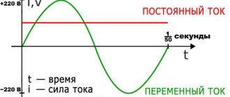
In 1879, Edwin Hall discovered that when a conductor or semiconductor with current flowing in one direction is injected perpendicular to a magnetic field, the voltage can be measured at right angles to the path of the current. It is well known that the Hall effect results from the interaction of charged particles such as electrons in response to electric and magnetic fields.
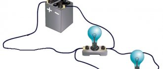
The Hall effect, when applied to sensors, manifests itself either as a measurable voltage difference across a conductor through which a direct current must flow, or as a measurable current difference across a conductor through which a constant voltage must flow (figure below). The voltage difference is proportional to the magnetic field strength. This means that the Hall effect can be used in two very different ways, even if the basic effect is the same in both cases.
The signal level due to the field change relative to the background noise is small (μV range). Therefore, its use requires rather complex signal paths.
Without wishing to in any way discount Edwin Hall's discoveries, this effect is indeed an extension of the use of the Lorentz force, which describes the interaction between electric and magnetic forces on a point charge due to a change in the electromagnetic field.
Simply put, in the case of the Hall effect, the Lorentz force describes the effect that a magnetic field has on a charged particle, specifically the direction it will be forced to take when passing through a conductor exposed to the magnetic field. Physical movement results in more or less charge on the surface of the conductor, resulting in a potential difference known as the Hall voltage.
Kinds
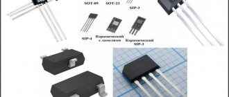
There are two types of Hall sensors:
- Digital sensors. They work to determine the magnetic field. If the induction reaches a certain limit, the sensor gives a signal about the presence of a magnetic field. If the limit is not reached, then the signal is zero. Weak induction and low sensitivity of the sensor do not give a signal of the presence of a field. The disadvantage of this type of sensor is that it has a threshold dead zone. Digital Hall sensors are divided into unipolar and bipolar:
- Unipolar Hall sensors operate if there is a field of any polarity, turning off when the induction decreases. — Bipolar Hall sensors are triggered by a change in field polarity. With one polarity, the sensor is turned on, and with the other, it is turned off.
- The analog type of Hall sensors changes the field induction into a potential difference. The value of the sensor depends on the polarity and its strength. It is necessary to take into account the distance at which the sensor is located.
Application
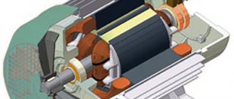
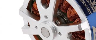
Hall sensors are included in many devices. They are most often used in measuring magnetic induction field strength, in electric motors, and in ion rocket engines. Hall sensors are widely used in the ignition systems of modern cars.
They are also used in proximity switches, reed switches, when measuring current, liquid level and other places. Their main advantage is the impact without physical contact.
Digital Hall sensor.
How to check the health of the Hall sensor on a car
In everyday life, motorists most often encounter this problem. The simplest way is to simply replace it with a working sensor. If the ignition system works after replacement, then the sensor needs to be replaced. If there is nothing to replace the sensor being tested, then a simple device is assembled that can simulate the operation of a Hall sensor. Take a piece of wire and a triple connector from the ignition distributor. These items work similar to a sensor.
To control, use a conventional multimeter. If the sensor fails, the tester will show 0.4 volts or less. The operation of the sensor is also checked by checking the spark when the ignition is connected. Before this, connect the ends of the wire to the outputs of the switch. If the malfunction does not occur on the car, but on other equipment, then a tester is needed. The test method will depend on the device in which the sensor is installed.
Hall sensors in smartphones
Mobile gadgets have many functional blocks. Among them there are auxiliary sensors, one of which is a Hall sensor. In modern communication devices, such sensors are measuring elements that are used to determine the power of the magnetic field and its changes. They are named after the scientist Hall.
Why is a Hall sensor installed in a smartphone?
This touch element has many possibilities. One of them is the measurement of magnetic induction of devices, as well as contactless control. Expensive smartphone models have a magnetometer, the operation of which is based on a Hall sensor.
It will be interesting➡ What is a pulse relay
On many mobile phones this sensor is not fully implemented. This sensor is mainly used for the following tasks:
- Digital compass. Used for navigation programs and increasing positioning speed.
- Optimizing the interaction of the device with various accessories, magnetic cases.
- Using a sensor in folding phone models to turn the screen on and off when the cover moves.
An example of how a magnetic Hall sensor in a case and a smartphone works is that when the case is opened and closed, the screen is automatically locked. The sensor responds to the movement of the magnet and to the strengthening of the magnetic field.
Hall sensor in a smartphone.
Features of using a Hall sensor in a car
In a car, a Hall sensor operates on the principle of a conventional key - a contactor and a circuit breaker. At the same time, the magnet rotates in the distributor and affects the sensor itself, which is fixed in a stationary manner. When the latter begins to “feel” the magnetic field, it begins to send impulses, which, in turn, cause a spark to ignite. For a car, the Hall sensor is one of the key elements of its ignition system and is present in any model, regardless of configuration and cost.
Sometimes this device can be used in digital car speedometers or tachometers, and can also be used to check the speed of transmission data and to monitor the operation of the car's anti-lock braking system.
In addition, this unit is highly reliable. It can work for many years, but breaks down, as a rule, due to strong physical impact or due to severe contamination. Very often the sensor is installed so that it can be easily removed and replaced at any time. The only exceptions are those devices that are used to monitor the most complex automotive systems.
Application of Hall sensor in a car
Measuring current using the Hall effect
The fact that the Hall effect depends on a magnetic field means that it can be used as a contactless technology. So it is not "intrusive" like the most common way of measuring current, which is to use a shunt (low ohm resistor) and measure the voltage drop across it. Using the Hall effect to measure current is inherently reliable in high power applications because it does not rely on ground potential as a reference.
For a conventional Hall effect current sensor, this means placing the sensor perpendicular to the magnetic field and using a concentrator, usually a ferromagnetic core shaped like a ring or square, placed around the conductor carrying the current being measured (picture below). The sensor is usually held in a small air gap formed between the two ends of the ferromagnetic core.
With an IMC-Hall current sensor, the sensing element is located parallel to the flowing current. In this case, a ferromagnetic core is not required; however, shielding may be required to protect against crosstalk. This means that it can be used to measure the current flowing through a PCB bus or trace by simply placing the sensor over the bus or trace. This type of sensor is activated by IMC-Hall technology using an integrated magnetic concentrator (IMC) developed by Melexis.
Essentially, it is a magnetic field generated by a current that is detected by the Hall effect rather than by the current flowing itself.
How to check the performance of the Hall sensor?
There are different ways to check the serviceability of the SBZ sensor; we will briefly talk about them:
- We simulate the presence of DH. This is the easiest way to quickly check. But its effectiveness can only be discussed if a spark does not form when there is power at the main components of the system. To test, follow these steps:
- disconnect the three-wire plug from the distributor;
- we start the ignition system and at the same time “short” the wire with ground and the signal from the sensor (pins 3 and 2, respectively). If there is a spark on the ignition coil, it can be stated that the SBZ sensor has lost its functionality and needs to be replaced.
Please note that in order to detect sparking, the high-voltage wiring must be close to ground.
- Using a multimeter to check. This is the most well-known method, and is given in the car manual. You need to connect the probes of the device, as shown in Figure 7, and measure the voltage.
Connection diagram of a multimeter for checking DC
On a working sensor, the voltage will fluctuate in the range from 0.4 to 11 volts (do not forget to switch the multimeter to DC measurement mode). It should be noted that checking with an oscilloscope will be much more effective. It is connected in the same way as a multimeter. An example of an oscillogram of a working DC is shown below.
Oscillogram of a working Hall sensor SBZ
- Installation of a known working HH. If there is another sensor of the same type available, or it is possible to borrow it for a while, then this option also has a place to exist, especially if the first two are difficult to do.
There is another verification option, which is similar in principle to the second method. It can be useful if you don't have measuring instruments at hand. For testing, you will need a 1.0 kOhm resistor, an LED, for example, from a lighter flashlight, and several wires. From this entire set we assemble the device in accordance with Figure 9.
Rice. 9. LED tester for checking DH
We carry out testing according to the following algorithm:
- Check the power supply to the sensor. For this purpose, we connect (observing polarity) our tester to terminals 1 and 3 of the DC. Turn on the ignition, if everything is normal with the power supply, the LED will light up, otherwise you will need to check the power circuit (after making sure that the LED is connected correctly).
- Let's check the sensor itself. To do this, we “transfer” the wire from the first terminal to the second (signal from the DC). After this, we begin to turn the camshaft (by hand or with a starter). The blinking of the LED will indicate the serviceability of the DC. Otherwise, just in case, we check that the polarity is correct when connecting the LED, and if it is done correctly, we replace the sensor with a new one.
Location tracking using the Hall effect
The same principle can be used to detect the presence, absence, or distance of a magnetic field. In fact, the Hall voltage resulting from the movement of the magnet over the sensors can be detected, amplified and processed. This makes it possible to use the Hall effect to determine the position or even orientation of objects relative to the sensor.
In a simple application this could be implemented relatively crudely, such as monitoring when a laptop is open or closed. Or it can be more complex when it is used to detect linear motion or rotation, such as a change in the position of a moving object (picture below). In this regard, using the Hall effect for position sensing is much more versatile than using it as a current sensor.
Purpose of DC in the car ignition system
Having understood the principle of operation of the Hall element, let's consider how this sensor is used in the contactless ignition system of the VAZ line of cars. To do this, let's look at Figure 5.
Rice. 5. Principle of the SBZ device
Designations:
- A – sensor.
- B – magnet.
- C – plate made of magnetically conductive material (the number of protrusions corresponds to the number of cylinders).
The operating algorithm of such a scheme is as follows:
- When the chopper-distributor shaft rotates (moving synchronously with the crankshaft), one of the protrusions of the magnetically conductive plate takes a position between the sensor and the magnet.
- As a result of this action, the magnetic field strength changes, which causes the DC to operate. It sends an electrical impulse to the switch that controls the ignition coil.
- The voltage required to form a spark is generated in the Coil.
It would seem nothing complicated, but the spark must appear at a certain moment. If it forms earlier or later, it will cause a malfunction of the engine, even stopping it completely.
Appearance of the Hall sensor for SBZ VAZ 2110
Built-in Magnetic Concentrator (IMC)
One of the disadvantages of most Hall sensors, which is related to the cause of the effect, is that the Hall plate used to sense the field is limited to only one axis.
To address this shortcoming, Melexis has developed an integrated magnetic concentrator, or IMC, which makes the Hall effect much more flexible. IMC allows Hall sensors to remain in plane to detect magnetic fields from the X, Y and Z axes (picture below). Therefore, the application advantages are numerous, including flexibility in sensor orientation.
Formulas and calculations
Since this effect is based on the Lorentz force, it is with its definition that the mathematical description of the resulting potential difference begins. The Lorentz force is determined from the following expression:
Fl=qvB, where:
- q is the particle charge;
- v is the speed of particle movement;
- B is the external magnetic field.
The electric field formed by the charges formed on the edges of the conductor also affects the electrons moving in the cross section. The strength of this influence is described as follows:
Fel=qE, where:
- q is the particle charge;
- E is the intensity of the internal electric field.
When the potential difference balances the magnetic field, the system is considered stable. In this case, the condition Fl = Fel is met. Therefore, the following two statements are also true:
qvB= qE
E=vB
The speed of electrons is usually determined using the current density formula:
j=qnv; v=j/qn, where:
- q is the particle charge;
- n is the number of particles per unit volume.
Now the electric field E can be described using the expression:
E=jB/qn
Let's find the potential difference:
Un=dE=djB/qn, where d is the thickness of the conductive plate.
This expression can be simplified using the so-called “Hall constant”, which has the form R=1/qn. The final formula for the potential difference will take the form:
Un=RdjB
That is, the potential difference is directly proportional to the thickness of the conductor, magnetic induction and current density.
Application of the Hall effect in the automotive industry
Thanks to the use of integrated magnetic concentrator technology, many applications in the automotive industry can take advantage of the Hall effect. Operating in three dimensions, the Hall sensor can be used to detect pedal position, steering column rotation and brake lever status, as well as the position of power seats.
It can also be used under the hood to monitor rotating parts of pumps and motors, and to measure the current drawn by electrified parts of the powertrain, such as the inverter, battery monitoring system (BMS) or on-board charger (OBC).
711 chip circuit
Chip ACS 711
ACS 711 is the same chip that will make it possible to produce a current sensor or TD based on a Hall sensor (Hall sensor). The BH of such a sensor will be almost 100 kHz, which will be quite effective for measurements.
This type of chip has an output that is integrated with the amplifier. The latter, in turn, due to its efficiency, is capable of increasing the circuit’s capabilities up to 1 A/V.
As for power supply, voltage is supplied to the amplifier through the use of an internal 2-polar type source. This could be the NSD10 variant or some other. The microcircuit itself is powered by a stabilizer having an output voltage of 3.3 V.
Results
In basic terms, the Hall phenomenon can be used in a number of useful ways, including current measurement and position determination. Despite significant challenges such as low signal-to-noise ratio or stray field effects, the electronics industry has succeeded in developing reliable and accurate sensor solutions based on the Hall effect.
In particular, the addition of a powerful analog front-end and digital signal path along with proprietary technologies such as Melexis' IMC-Hall means that the Hall effect can be applied to current sensing and positioning even in harsh environments such as the automotive industry.