Resonance effect
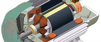
A striking example of the mechanical class of resonators is the spring pendulum. Professor from the Massachusetts Institute of Technology (in America), V. Levin, focuses the attention of his students on the fact that resonance is an effect associated with an increase in amplitude. An installation is used to demonstrate the phenomenon. It consists of the following components:
- electric motor;
- a mechanism that turns rotation into reciprocating motion;
- LATR – laboratory autotransformer;
- copper wire spring with a set of weights;
- spring guide.
The direction of spring oscillation is vertical. The rotation of the motor shaft causes the spring to oscillate. Using an autotransformer, it is possible to regulate the voltage. The adjustment allows you to vary the frequency of rotation of the shaft and oscillations of the pendulum. When the shaft rotation speed changes, the amplitude of the reciprocating motion remains unchanged.
Before the experiment, the elongation of the copper spring under the action of weights is measured (to estimate the resonant frequency of the spring). Changing the speed of rotation of the shaft causes the amplitude of oscillation of the end of the spring with the load to change. The amplitude increases and at the 1st hertz of frequency it becomes maximum (~30 cm).
Important! With a further increase in the shaft rotation speed, the amplitude of the end of the spring begins to decrease. This means that resonance has passed. If you reduce the voltage, and with it the engine speed, you can again observe the effect of resonance oscillations of the spring.
Spring pendulum
The quality factor of the spring Q is defined as the ratio of the oscillation amplitude of the spring Apr to the oscillation amplitude of the driving force Aavs. In this case, Q = Apr/Avs = 30/5 = 6, where Avs = 5.
RLC Series Resonance
Let's consider a series resonator circuit.
RLC circuit
As can already be seen from the diagram, for the description we need to write down the equation of the input impedance.
\Large Z_{in} = R + jwL — j\frac{1}{wC} (1)
Further, to understand the processes taking place, it is convenient to work with capacities. Let's write the total power in the RLC circuit
\Large P = V_{rms} \cdot I_{rms} = \frac{V \cdot I}{ \sqrt{2}\cdot \sqrt{2}} = \frac{V \cdot I}{2} (2)
The equation involves the root of two, since the effective value of alternating current and voltage is used.
Now we write the power in complex form through the impedance from the equation (1).
\Large P=\frac{I^{2}Z_{in} }{2}= \frac{1}{2} I^{2} \cdot (R + jwL - j\frac{1}{wC} )
Let's open the brackets
\Large P=\frac{1}{2} I^{2}R + \frac{1}{2} I^{2}jwL — \frac{1}{2} I^{2}\frac{ j}{wC} (3)
Let's stop at this point and carefully look at what we got.
Parts of the equation
For greater clarity, we will describe each power and energy using the root mean square (also known as effective) value of current or voltage.
Recall that the effective value for a sinusoidal signal is found as:
\Large V_{rms} = \frac{V_{max}}{\sqrt{2}}
Then the power dissipated by the resistor is:
\Large P_{r} = \frac{I^{2}R}{2}
Energy accumulated in inductance:
\Large W_{L}= \frac{LI_{rms}^{2}}{4}
The energy accumulated in the capacitor, but expressed in terms of current:
\Large W_{C}= \frac{CU_{rms}^{2}}{2} = \frac{I_{rms}^{2}}{4\cdot Cw^{2} }
Let's return to expression (3) and write it using the powers and energies from the equations above.
\Large P = P_{r} + 2jw(P_{L}-P_{C}) (4)
This shows that resonance occurs when the accumulated energies in the capacitor and inductance become equal. Or, if we turn to equation (1) , the impedance of the inductor becomes equal to the impedance of the capacitor. The resonance point is characterized by the minimum input resistance (Z_in = R).
In an impedance plot, series resonance is shown in the figure below.
Impedance versus frequency.
As already mentioned, conditions for resonance arise when WL=WC. Let's equate the two energies.
\Large \frac{LI_{rms}^{2}}{4} = \frac{I_{rms}^{2}}{4\cdot Cw^{2} }
From here it is easy to find the resonant frequency.
\Large w_{0} = \frac{1}{\sqrt{LC}}
Next, we will find another important parameter characterizing the resonant circuit - this is the quality factor . Quality factor is often used to describe the amount of loss in a circuit. Also, using the quality factor, you can determine how susceptible the RLC circuit as a whole is to fluctuations.
In essence, the quality factor is the ratio of the accumulated (stored) energy in a cycle to the energy lost. Denoted as Q.
\Large Q_{0} =w_{0} \frac{W_{stor}}{W_{loss}} = w_{0} \frac{W_{L}+W_{C}}{W_{loss}} (5)
Let's next look at the formula for the quality factor for the resonant frequency w0. As already written above, at the resonance frequency the energy in the capacitor and in the inductance are equal. Let's take this into account in the formula (5).
\Large Q_{0} =w_{0} \frac{2W_{L}}{W_{R}} = w_{0} \frac{2\cdot \frac{I^{2}L}{4}} {\frac{I^{2}R}{2}} = w_{0} \frac{L}{R}
The same thing can be written through the energy of a capacitor.
\Large Q_{0} =\frac{1}{w_{0}RC}
The last thing to note about series resonance is the resonance bandwidth. What it is? In words, this can be described as follows: the passband for a resonant circuit is the frequency region that lies within the boundaries where the power dissipated by the resistor is less than half of the total power of the system. You can find the bandwidth like this:
\Large BW = w_{0} \frac{1}{Q_{0}}
The band boundaries can be found in a simple way, for example, from the frequency w0, step back in each direction by BW/2. This can also be done through the transfer function for the RLC circuit in relation to the resistor. Let's write the transfer function as the ratio Vr/Vin.
\Large \frac{V_{r}}{V_{in}} = \frac{IR}{I(R+jwL+\frac{1}{jwC})} = \frac{R}{R+\frac{( jw)^{2}LC+1}{jwC}}
Next, we multiply each term of the equation by jwC/jwC
\Large \frac{V_{r}}{V_{in}} = \frac{jwRC}{jwRC-w^{2}LC+1}
Now we find the module of the transfer function. Let me remind you that the module for complex numbers is found as:
\Large \sqrt{(RE)^{2}+(IM)^{2}}
Now let's write down the final version of the transfer function module.
\Large \left | \frac{V_{r}}{V_{in}} \right | = \frac{wRC}{\sqrt{(wRC)^{2}+(1- w^{2}LC)^{2}}} (6)
After we have written down the transfer function, let's return to determining the bandwidth. The passband for a resonant circuit is the frequency region that lies within the boundaries where the power dissipated by the resistor is less than half of the total power of the system.
In other words, to find the bandwidth, you need to set the conditions where half of the total power will be dissipated on the resistor. To do this, the amplitude across the resistor must be at least equal to:
\Large \frac{1}{\sqrt{2}}V_{max}
Knowing these conditions, let’s return to the equation taking into account the above (6).
\Large \frac{1}{\sqrt{2}} = \frac{wRC}{\sqrt{(wRC)^{2}+(1- w^{2}LC)^{2}}} (7)
Now we can solve equation (7) for w. After solving we get the following roots:
\Large w_{1,2} = (\sqrt{1+(\frac{R}{2\sqrt{\frac{L}{C}}})^{2}} \pm \frac{R}{ 2\sqrt{\frac{L}{C}}})_{w0}
Let's highlight the obtained frequencies on the impedance graph, which appeared above.
RLC Bandwidth
Parameters for construction.
Mathcad listing.
Definition of an Oscillatory Circuit
Rotation speed: formula
Resonance phenomena noted in electrical engineering are clearly expressed in the circuits of oscillatory circuits (OC). Such designs are elementary systems capable of carrying out free oscillations of an electromagnetic nature. The CC itself in the circuit consists of the following elements:
- capacitor;
- inductors;
- current source.
Attention! The terminals of the circuit elements can be connected to each other in parallel or in series. It all depends on what result you want to achieve from resonance in the CC.
§56. Voltage resonance and current resonance
The phenomenon of resonance.
An electrical circuit containing inductance and capacitance can serve as an oscillatory circuit, where the process of oscillations of electrical energy occurs, passing from inductance to capacitance and back. In an ideal oscillatory circuit, these oscillations will be undamped.
When an oscillatory circuit is connected to an alternating current source, the angular frequency of the source ω may turn out to be equal to the angular frequency ω0 with which electrical energy oscillates in the circuit. In this case, the phenomenon of resonance occurs, i.e., the coincidence of the frequency of free oscillations ω0 occurring in any physical system with the frequency of forced oscillations ω imparted to this system by external forces.
Resonance in an electrical circuit can be obtained in three ways: by changing the angular frequency ω of the alternating current source, inductance L or capacitance C. A distinction is made between resonance with a series connection of L and C - voltage resonance, and with a parallel connection - current resonance. The angular frequency ω0 at which resonance occurs is called the resonant, or natural frequency of oscillation of the resonant circuit.
Voltage resonance.
At voltage resonance (Fig. 196, a), the inductive reactance XL is equal to the capacitive reactance Xi, the total resistance Z becomes equal to the active resistance R:
Z = √( R2 + [ω0L – 1/(ω0C)]2 ) = R
In this case, the voltages across the inductance UL and capacitance Uc are equal and are in antiphase (Fig. 196, b), therefore, when added, they compensate each other. If the active resistance of the circuit R is small, the current in the circuit increases sharply, since the reactance of the circuit X = XL—Xc becomes zero. In this case, the current I is in phase with the voltage U and I=U/R. A sharp increase in current in the circuit during voltage resonance causes the same increase in voltages UL and Uc, and their values can be many times higher than the voltage U of the source feeding the circuit.
The angular frequency ω0, at which resonance conditions occur, is determined from the equality ωoL = 1/(ω0С).
Rice. 196. Scheme (a) and vector diagram (b) of an electrical circuit containing R, L and C, with voltage resonance
From here we have:
ωo = 1/√(LC) (74)
If you smoothly change the angular frequency ω of the source, then the total resistance Z first begins to decrease, reaches its lowest value at voltage resonance (at ωo), and then increases (Fig. 197, a). In accordance with this, the current I in the circuit first increases, reaches its highest value at resonance, and then decreases.
Rice. 197. Dependence of current I and impedance Z on ω for series (a) and parallel (b) alternating current circuits
Resonance of currents.
Current resonance can occur when inductance and capacitance are connected in parallel (Fig. 198, a). In the ideal case, when there is no active resistance in parallel branches (R1 = R2 = 0), the condition for current resonance is the equality of the reactances of the branches containing inductance and capacitance, i.e. ωoL = 1/(ωoC).
Rice. 198. Electrical circuit (a) and vector diagrams (b and c) with current resonance
Since in the case under consideration the active conductivity G = 0, the current in the unbranched part of the circuit at resonance is I=U √(G2+(BL-BC)2)= 0. The current values in the branches I1 and I2 will be equal (Fig. 198,b) , but the currents will be shifted in phase by 180° (the current IL in the inductance lags in phase from the voltage U by 90°, and the current in the capacitance I c leads the voltage U by 90°).
Consequently, such a resonant circuit represents an infinitely large resistance for current I and electrical energy does not enter the circuit from the source. At the same time, currents IL and Ic flow inside the circuit, i.e. there is a process of continuous exchange of energy within the circuit. This energy moves from inductance to capacitance and back.
As follows from formula (74), by changing the values of capacitance C or inductance L, you can change the oscillation frequency ω0 of electrical energy and current in the circuit, i.e., adjust the circuit to the required frequency.
If there were no active resistance in the branches in which the inductance and capacitance are included, this process of energy oscillation would continue indefinitely, i.e., undamped oscillations of energy and currents IL and Ic would arise in the circuit.
However, real inductors and capacitors always absorb electrical energy (due to the presence of active wire resistance in the coils and the occurrence of bias currents in the capacitors that heat the dielectric), therefore, when the currents resonate, some electrical energy enters the real circuit from the source and flows through the unbranched part of the circuit some current I.
The condition for resonance in a real resonant circuit containing active resistances R1 and R2 will be the equality of the reactive conductivities BL = BC of the branches, which include inductance and capacitance.
From Fig. 198, c it follows that the current I in the unbranched part of the circuit is in phase with the voltage U, since the reactive currents 1L and Ic are equal, but opposite in phase, as a result of which their vector sum is zero.
If in the parallel circuit under consideration we change the frequency ωо of the alternating current source, then the total resistance of the circuit begins to increase, reaches its highest value at resonance, and then decreases (see Fig. 197,b). In accordance with this, the current I begins to decrease, reaches its lowest value Imin = Ia at resonance, and then increases.
In real oscillatory circuits containing active resistance, each current fluctuation is accompanied by energy losses. As a result, the energy imparted to the circuit is consumed quite quickly and the current fluctuations gradually die out. To obtain undamped oscillations, it is necessary to constantly replenish the energy losses in the active resistance, i.e., such a circuit must be connected to an alternating current source of the corresponding frequency ω0.
The phenomena of voltage and current resonance and the oscillatory circuit have become very widely used in radio engineering and high-frequency installations. Using oscillatory circuits, we obtain high-frequency currents in various radio devices and high-frequency generators.
The oscillatory circuit is the most important element of any radio receiver. It ensures its selectivity, i.e. the ability to distinguish signals from a specific radio station from radio signals with different wavelengths (i.e., different frequencies) sent by different radio stations.
Connecting to the inductive coil circuit
Current frequency
The inclusion of an inductor in the capacitive circuit immediately turns it into a CC. Depending on the connection diagram, there are two types of class 1 CCs: parallel and serial.
Parallel QC
In this circuit, capacitor C is connected to coil L in parallel. If a charged capacitor is connected to a coil, the energy stored in it will be transferred to it. A current will flow through the inductive coil L, causing an electromotive force (EMF).
The self-induction emf L will be aimed at reducing the current in the parallel circuit. The current created by this EMF and the discharge current of the capacitor are initially identical, and their total value is zero. The capacitor will transfer its energy Ec to the coil and will be completely discharged. The inductance, having received the maximum magnetic energy EL, will begin to charge the capacitor with a voltage of a different polarity. When all the energy from the inductance goes into the capacitor, the capacitor will be fully charged. Oscillations appear in the circuit; such a circuit is called an oscillatory circuit.
Parallel QC
For your information. If there were no losses in such a circuit, then such oscillations would never begin to fade. In practice, the duration of the process depends on the energy loss. The greater the losses, the shorter the duration of the oscillations.
Parallel connection of C and L causes current resonance. This means that the currents passing through C and L are higher in value than the current through the circuit itself by a specific number of times. This number is called the quality factor Q. Both currents (capacitive and inductive) remain inside the circuit because they are in antiphase, and their mutual compensation occurs.
It is worth noting! At fres, the value of R KK tends to infinity.
Sequential QC
In this circuit, a coil and a capacitor are connected in series with each other.
Sequential QC
In such a circuit, voltage resonance occurs, R of the circuit tends to zero in the event of the formation of a resonant frequency (fres). This allows a similar resonance system to be used as a filter.
What is resonance?
Definition of the phenomenon by TOE: electrical resonance occurs in an electrical circuit at a certain resonant frequency, when some parts of the resistance or conductivity of the circuit elements cancel each other. In some circuits, this occurs when the impedance between the input and output of the circuit is almost zero and the signal transfer function is close to unity. In this case, the quality factor of this circuit is very important.
Connection of two branches at resonance
Signs of resonance:
- The components of the reactive branches of the current are equal to each other IPC = IPL, antiphase is formed only when the net active energy at the input is equal;
- The current in individual branches exceeds the entire current of a particular circuit, while the branches are in phase.
In other words, resonance in an AC circuit implies a special frequency, and is determined by the values of resistance, capacitance and inductance. There are two types of current resonance:
- Consistent;
- Parallel.
For series resonance, the condition is simple and is characterized by minimal resistance and zero phase, it is used in reactive circuits, and it is also used in branched circuits. Parallel resonance or the concept of an RLC circuit occurs when the inductive and capacitive inputs are equal in magnitude but cancel each other out since they are at an angle of 180 degrees from each other. This connection must be constantly equal to the specified value. It has received wider practical application. The sharp minimum impedance that it exhibits is beneficial for many electrical household appliances. The sharpness of the minimum depends on the resistance value.
An RLC circuit (or circuit) is an electrical circuit that consists of a resistor, inductor, and capacitor connected in series or parallel. The RLC parallel oscillating circuit gets its name from the abbreviation of the physical quantities representing resistance, inductance and capacitance, respectively. The circuit forms a harmonic oscillator for the current. Any oscillation of the current induced in the circuit fades over time if the movement of the directed particles is stopped by the source. This resistor effect is called attenuation. The presence of resistance also reduces the peak resonant frequency. Some resistance is unavoidable in real circuits, even if a resistor is not included in the circuit.
Resonance frequency
When an alternating voltage with a varying frequency is applied to two CCs (parallel and series) their reactances C and L will change. Changes occur as follows:
- with increasing f, the capacitive reactance decreases and the inductive reactance increases;
- as f decreases, capacitive reactance increases and inductive reactance decreases.
Resonance - what is it?
The frequency at which the reactances of both circuit elements are equal is called resonant.
Important! At fres, the resistance of the parallel CC will be maximum, and the resistance of the serial CC will be minimal.
The resonant frequency formula is:
fres = 1/2π*√L*C,
Where:
- L – inductance, H;
- C – capacity, F.
By substituting the known values of capacitance and inductance into the formula for the resonant frequency of an oscillatory circuit of any configuration, this parameter can be calculated.
To determine the oscillation period of the CC and the resonance frequency, you can use the online calculator on the corresponding portal on the network. The professional program has a simple interface.
An example of the interface of an online LC circuit calculator
The phenomenon of resonance of electrical circuits
| Christiaan Huygens, creator of the wave theory |
| Carl Friedrich Gauss, developer of retarded potential theory |
| Wilhelm Weber, discoverer of the laws of electromagnetism |
| Hermann Helmholtz, great physicist, mathematician and philosopher, founder of the wave theory |
| Heinrich Hertz, discoverer of the photoelectric effect and microwave waves in the ether, 1887 |
| Robert Hooke, creator of the theory of elasticity, microscope, theory of gravity |
| Emilius Lenz, discoverer of the laws of electromagnetism |
| J. Maxwell, creator of the theory of ether electromagnetism |
| A. S. Popov, inventor of radio - transmitting signals over the air, 1895 |
| Nikola Tesla, the brilliant inventor of the transformer |
back to contents Reznans in physics
Series resonance, voltage resonanceThe series resonant circuit is shown in Fig. 1 a). The complex resistance of the circuit is equal to
The resonance condition from expression (1) will be
Thus, resonance in the circuit occurs regardless of the value of the resistive resistance R when the inductive reactance
All quantities included in expression (3) are positive, therefore these conditions are always satisfied, i.e. resonance in a series circuit can be created
The greatest interest for practice is frequency variation. Therefore, let us consider the processes in the circuit under this condition. When the frequency changes, the resistive component of the complex resistance of the circuit Z remains constant, but the reactive one changes. Inductive and capacitive reactances vary with frequency as shown in Fig. 2. When the frequency tends to zero , XC -> ∞, xL -> 0, and φ -> -90° (Fig. 1 b)). With an infinite increase in frequency - xL -> ∞, Let us now consider the voltage drops across the circuit elements. Let the resonant circuit be powered from a source that has the properties of an EMF source, i.e. circuit input voltage u = const, and let the current in the circuit be equal to
Moving from amplitude values to effective values, from expression (4) we obtain voltages on individual circuit elements
and at the resonant frequency
where is a quantity that has the dimension of resistance and is called wave or characteristic impedance contour. Therefore, when resonance e
Ratio of characteristic impedance to resistive ρ/ R = Frequency characteristics of the circuitLet's consider the dependence of voltage and current in the circuit on frequency. To make a generalized analysis possible, let us pass in expressions (5) to relative units, dividing them by the input voltage at resonance U =
where i = I / The absolute and relative current in the circuit is equal to
From expressions (7) and (8) it follows that the nature of the change in all quantities when the frequency changes depends only on the quality factor of the circuit. Graphic representation of them at Q =2 is shown in Fig. 3 on logarithmic (a) and linear (b) scales of the abscissa axis. In Fig. 3 curves A (v), , (9) and the relative frequencies of the maxima are equal (10) With increasing quality factor Q -> ∞, As the quality factor decreases, the maxima of the curves u L (v) and uС The voltage across the resistor and the current in the circuit have a maximum of 1.0 at the resonant frequency. If the absolute values of the current or voltage across the resistor are plotted on the ordinate axis, then for different values of the quality factor they will have the form shown in Fig. 4. In general, they give an idea of the nature of changes in quantities, but it is more convenient to make comparisons in relative units. In Fig. 5 shows the curves of Fig. 4 in relative units. It can be seen here that an increase in the quality factor affects the rate of change of current when the frequency changes. It can be shown that the difference in relative frequencies corresponding to the values of the relative current is equal to the damping of the circuit D =1/ Let us now move on to analyzing the dependence of the phase shift between current and voltage at the circuit input on frequency. From expression (1) the angle φ is equal to
As one would expect, the value of φ is determined by the quality factor of the circuit. Graphically, this dependence for two values of quality factor is shown in Fig. 6. As the frequency decreases, the phase shift value tends to a value of -90°, and with an increase to +90°, passing through zero at the resonance frequency. The rate of change of the function φ (v) is determined by the quality factor of the circuit. Series resonance with current sourceThe series resonant circuit can also be powered from a source of electrical energy that has the properties of a current source, i.e. providing constant current to the load. Expressions (5) remain valid in this case, but the current in them will be constant. UR will be constant =
In expression (12), the quality factor is also the ratio of the wave impedance to the resistive Q = ρ/ The total relative voltage drop at the input of the circuit is the hypotenuse of the voltage right triangle, so
Functions u L (v) and u Graphical representation of functions u L (v)= For the function u (v) = C (v) it can be shown that the difference between the relative frequencies v 1 and v 2 corresponding to the values is equal to the damping of the circuit The phase characteristics of the circuit when powered from a current source are no different from the characteristics of the power mode from an EMF source (Fig. 6). Comparing the frequency characteristics when powering a series resonant circuit from a current source with the characteristics when powering it from an EMF source, we can draw the following conclusions:
Current resonance, parallel resonanceThe resonance mode can also be created with a parallel connection R ,
Consequently, for a parallel circuit the same variations of parameters are possible as for a sequential one and the expressions for them will be identical
Y changes , therefore its end moves on the complex plane along a straight line parallel to the imaginary axis and passing through the point For a parallel connection, the currents in individual elements can be represented in terms of conductances and the total voltage drop U as
U in resonance mode 0, then the currents in individual elements will be
where is the wave or characteristic conductivity contour. Voltage drop at the circuit input U when powered from a source that has the properties of a current source and generates a current with an effective value
Hence, the input voltage in resonance mode U 0 =
Expressions (18) completely coincide with expressions (7) and (8) for the frequency characteristics of a series circuit, if the relative currents and voltages in them are swapped. Therefore, the characteristics of Fig. 3 will be related to expressions (18) as follows: A (v)=i From expression (14), the qualitative phase frequency response discussed above can be represented analytically in the form those. it coincides with the characteristic of the series circuit, but has the opposite sign. Parallel resonance with an EMF sourceLet us now assume that the parallel circuit is powered by a source with the properties of an EMF source. In resonance mode, the input current will also be equal to the current through the resistor - I 0=
The relative input current i can be determined using the fact that in the current triangle it is the hypotenuse
Expressions (19) and (20) for relative currents coincide with expressions (12) and (13) for relative voltages of a series circuit. Therefore, in Fig. 7 - i C (v )= Comparing the frequency characteristics when powering a parallel resonant circuit from a current source with the characteristics when powering it from an EMF source, we can draw conclusions similar to those that were made for a series circuit:
Resonance in real circuitsThe parallel resonant circuit may contain resistive resistances (Fig. 10). In this case, the complex conductivities of the branches will be equal Y1= G 1+ and the total conductivity Y= Y 1 + The resonance condition will be: Expanding expression (23) through the circuit parameters, we obtain , whence the resonant frequency ω р -
where is the resonant frequency in the simplest parallel circuit (Fig. 8 a)), and is the characteristic impedance of the simplest parallel circuit. Analysis of expression (21) shows that with different resistive resistances If R 1 = However, under this condition, it is possible that R 1 = The branches of the circuit are connected in parallel and the total voltage drop across them is the same and equal to the sum of the voltage drops across the elements of the branch. For any changes in frequency, the angle between the voltage on the resistor and the reactive element is 90°, etc. their sum is constant and equal to the input voltage, then the geometric location of the end points of the voltage drop vector across the resistor will be a semicircle (Fig. 11 a)). Moreover, the vectors of the branch with inductance will fit into the lower semicircle, and the branches with capacitance will fit into the upper. Input current I is equal to the sum of the currents of the branches Let us divide the complex numbers corresponding to the stress vectors in Fig. 11 a), on R = See also: Amplitude and frequency of free oscillations in the circuit Forced oscillations and resonance Voltage resonance Current resonance Bandwidth of the circuit back to contents Reznans in physics Did you know, that, like any idolatrous religion, relativism is fundamentally false. It contradicts the facts. Among them are the following: 1. An electromagnetic wave (in the religious terminology of relativism - “light”) has a strictly constant speed of 300 thousand km/s, absurdly not measured from anything. In reality, EM waves have different speeds in matter (for example, ~200 thousand km/s in glass and ~3 million km/s in the surface layers of metals, different speeds in the ether (see the article “Ether Temperature and Redshifts”), different speeds for different frequencies (see the article "On the speed of EM waves") 2. In relativism, "light" is a mythical phenomenon in itself, and not a physical wave, which is a disturbance of a certain physical medium. Relativistic "light" is a disturbance of nothing in nothing. It does not have a carrier medium for oscillations. 3. In relativism, manipulations with time (slowdown) are possible, therefore the principles of causality and the principle of strict logic, fundamental to any science, are violated. In relativism, at the speed of light, time stops (therefore it is absurd to say in it about the frequency of the photon). In relativism, such violence against the mind is possible, such as the statement about the mutual excess of the age of twins moving at sublight speed, and other mockeries of logic inherent in any religion. 4. In gravitational relativism (GTR), contrary to the observed facts, it is stated about the angular deflection of EM waves in empty space under the influence of gravity. However, astronomers know that light from eclipsing double stars is not subject to such deviation, and those “facts confirming Einstein’s theory” that were allegedly observed by A. Eddington in 1919 in relation to the Sun are falsifications. Read more in the FAQ on ethereal physics. |
Application of oscillatory circuits
A detailed calculation of the oscillatory circuit allows you to accurately select the size of the required CC elements. This allows them to be used in electronic circuits in the form:
- frequency filters - in radio receivers, signal generators, converters and rectifiers;
- oscillatory circuits - for isolating and tuning a broadcast station to a specific frequency;
- power resonance filters – for generating a sinusoidal voltage.
On civil aviation aircraft, CC is used in generator frequency control units.
Resonance in AC circuit
Let's remember that a vector diagram of the voltage amplitudes across the resistor, capacitor and coil helped us derive Ohm's law for a section of an alternating current circuit containing a resistor, an inductor, a capacitor and an alternating voltage source.
We have shown that the amplitude of the applied voltage must be equal to the geometric sum of these amplitudes. The angle between the amplitudes of the applied voltage and current determines the phase difference between the current and voltage. The tangent of this angle, as can be seen from the figure, is equal to the ratio of the difference in voltage amplitudes across the coil and capacitor to the voltage amplitude across the active resistance:
Using Ohm's law for a section of a circuit, it is easy to show that the same angle is determined by the ratio of reactance to active resistance:
And the average power released in the circuit across the active resistance will be determined by the expression presented on the screen:
Here cos φ
0 is
the power factor
. Being a dimensionless physical quantity, it characterizes the consumer of alternating electric current from the point of view of the presence of a reactive component in the load, and shows how much the alternating current flowing through the load is phase shifted relative to the voltage applied to it.
From the last two formulas it follows that if the reactance of the circuit is zero, then the equation for power will take the form we are familiar with:
In this case, maximum power is released in the circuit - the phenomenon of resonance occurs.
Resonance in an electrical oscillatory circuit is the phenomenon of a sharp increase in the amplitude of forced oscillations of current or voltage when the frequency of the external alternating voltage coincides with the natural frequency of the oscillatory circuit:
Let's consider this phenomenon in more detail. To begin with, let’s imagine that we are swinging a pendulum, acting on it with a periodically changing force. In this case, the pendulum will oscillate not independently, not freely, but under the influence of a periodic external force. Such oscillations of the pendulum, as we remember, are called forced oscillations
.
Forced electromagnetic oscillations can also occur in electrical oscillatory circuits. If in any oscillatory circuit, consisting of an inductor and a capacitor, an alternating current generator operates all the time, then the emf of the generator will cause an alternating electric current in this circuit, the frequency of which will be equal to the oscillation frequency of the emf of the generator.
The frequency of these forced oscillations in the general case does not coincide with the frequency of the circuit’s natural oscillations:
When the natural frequency of the oscillatory circuit is far from the frequency of the EMF acting in the circuit, the total resistance of the circuit is high and the current in it is insignificant. However, if in such a circuit the capacitance of the capacitor and the inductance of the coil are selected so that their resistances are equal, then the phase difference between the fluctuations in current and voltage will become equal to zero, that is, changes in current and voltage will occur in phase:
Thus, the condition for the occurrence of resonance in an oscillatory circuit is that the frequency of the external voltage supplied to the circuit is equal to the frequency of the circuit’s natural oscillations:
This frequency is called resonant.
Under this condition, the total resistance of the circuit becomes the smallest and equal to the active resistance, and the amplitude of the current at a given voltage takes on the greatest value. In this case, the voltage amplitude across the active resistance is equal to the amplitude of the external voltage applied to the circuit section ( U
0
r
=
U
0), and the voltages on the inductor and capacitor are equal in magnitude and opposite in phase:
Please note that the amplitude values of the resonant voltages on the coil and capacitor are equal, and they can significantly exceed the amplitude of the applied voltage:
This phenomenon is called voltage resonance.
Moreover, the lower the active resistance of the circuit, the stronger the current in the circuit and the steeper the resonant curve.
This case is usually called acute resonance.
A circuit with a sharp resonance is very sensitive to fluctuations in the resonant frequency. This is widely used in radio and electrical engineering to amplify voltage fluctuations of a specific frequency.
For example, radio waves from various transmitting stations excite alternating currents of different frequencies in the antenna of a radio receiver, since each transmitting radio station operates at its own frequency. An oscillatory circuit is inductively coupled to the antenna, in the coil of which forced oscillations of current and voltage occur. But only during resonance, from the oscillations of various frequencies excited in the antenna, the circuit selects only those whose frequency is equal to its own frequency. Tuning the circuit to the desired frequency is usually done by changing the capacitance of the capacitor.
Now let's look at a section of an AC circuit containing a capacitor and an inductor connected in parallel.
Let us assume that the active resistance of the circuit is so small that it can be neglected. Let an alternating voltage be applied to this circuit, varying according to the sine law:
Then the current passing in the branch with capacitive reactance will be in phase ahead of the applied voltage by π
/2.
And passing in the branch with inductive reactance - lag in phase by π
/2 from the applied voltage:
Thus, the phase difference of the currents in the two branches is equal to π
, that is, the current oscillations in the branches are opposite in phase. The amplitude of the current in the external circuit is equal to the magnitude of the difference in the amplitudes of the current strengths of both branches:
If the oscillation frequency in the circuit is equal to the resonant frequency, then the amplitude values of the current strengths in the branches will be equal, and the amplitude of the current strength in the external circuit will become equal to zero.
Of course, if we take into account the presence of active resistance, the phase difference will not be equal to π
, just as the amplitude value of the current in the external circuit will not be equal to zero. But it will take the smallest possible value. In this case, the amplitudes of current strengths in the branches can significantly exceed the amplitude of the current in the external circuit.
The phenomenon of a sharp decrease in the amplitude of the current in the external circuit feeding a capacitor and inductor connected in parallel, as the frequency of the applied voltage approaches the resonant frequency, is called current resonance (or parallel resonance).
This phenomenon is used in resonant amplifiers, which make it possible to isolate one specific oscillation from a signal of a complex shape, as well as in induction furnaces, so that the current in the supply wires is much less than the current in the coil.
To reinforce the new material, let’s solve this problem with you. A circuit consisting of a capacitor with a capacity of 507 μF, a coil with an inductance of 20 mH and a resistor with a resistance of 100 Ohms is connected in series to an alternating current network with a frequency of 50 Hz and a voltage of 220 V. Determine the current strength in the circuit, the phase shift between voltage and current, as well as the resonant circuit frequency.
Resonance amplitude
In a CC, when an alternating voltage is applied from an external source, two types of resonance and a sharp increase in two types of amplitude are observed: current amplitude and voltage amplitude.
Current amplitude
The current amplitude increases sharply with voltage resonance in the series circuit (series resonance). The source of alternating EMF is connected to a circuit where the series-connected elements L and C serve as the load.
In this case, the circuit includes resistances: active r and reactive x, equal to:
x = xL – xC.
Since for internal oscillations xL and xC are equal, then for the current supplied from the generator, at resonance (when the frequencies coincide) these values are also the same. Therefore x = 0. As a result, the total resistance of the circuit will consist of only a small active resistance. This results in maximum current.
Scheme (a) and resonance curves (b) for voltage resonance
Voltage amplitude
Current resonance (parallel resonance) is a condition for a sharp increase in voltage amplitude. The EMF source is connected outside the circuit and loaded by elements L and C connected in parallel. In this case, the resonance effect is affected by the internal resistance of the generator. The voltage amplitude on the circuit is maximum when the difference between the circuit voltage and the generator voltage is small. This is possible with small Ri.
Attention! Changing the generator frequency changes the current, and the voltage amplitude on the circuit does not lag behind the voltage on the generator. If, U = E - I*Ri, where E is the emf, I is the current, then at small Ri U = E.
Scheme (a) and resonance curves (b) for current resonance
The formula for determining the calculated resonant frequency for different oscillatory systems differs in the parameters included in it. Despite all the differences, the essence remains the same: the resonance effect occurs when the frequency of internal oscillations of the system and external influences become equal to each other.
Difference between series and parallel resonance
Main difference
The main difference between series resonance and parallel resonance is that series resonance occurs when the lowest impedance is generated by the arrangement of components, whereas parallel resonance occurs when the highest impedance is generated by the arrangement of components.
Series Resonance vs Parallel Resonance
At series resonance, the series RLC circuit has a minimum impedance at the resonant frequency. On the other hand, in parallel resonance, the parallel RLC circuit has maximum resistance at the resonant frequency. In series resonance, the series RLC circuit consists of maximum current flow at the resonant frequency; In contrast, with parallel resonance, the parallel RLC circuit consists of minimal current flow at the resonant frequency. In a series resonant circuit, the effective impedance is defined as R (the resistance of the resistor); On the other hand, with parallel resonance, the effective impedance is determined by the inductance and capacitance (L/CR).
The resonant frequency in a series resonant circuit is given as 1/(2 * π * (LC) 0.5); on the other hand, the resonant frequency in a parallel resonant circuit is given by (1/2 * π) * {(1 / LC) - R 2 / L 2 } 0.5. The series resonant circuit increases the voltage in the circuit; In contrast, a parallel resonant circuit typically increases the current present in the circuit. A series resonant circuit is also known as a receiving circuit; On the other hand, a parallel resonant circuit is also known as a refractive circuit.
The power factor in a series resonant circuit is equal to unity; on the contrary, the power factor in a parallel resonant circuit also contains unity. A series resonant circuit has maximum conductivity under resonance conditions; on the other hand, a parallel resonant circuit has minimal conductivity under resonance conditions. The RLC series circuit equation for effective impedance is usually written as Z 0 = R; on the other hand, the parallel RLC circuit equation for the effective impedance is usually written as Z0 = L/CR.
In a series resonant circuit, the quality factor is set as 0 L / R; on the contrary, in a parallel resonant circuit, the quality factor is usually given as R / Ѡ 0 L. Around the world, applications for a series resonant circuit include that they are used for tuning purposes, used as an oscillator circuit, used as a voltage amplifier, used in a communication system for signal processing used as a high frequency filter circuit, while the main applications for parallel resonance are for tuning purposes, used in induction heating system, used as a current amplifier, used as a filter circuit used in RF amplifiers.
comparison table
| Series resonance | Parallel resonance |
| A series circuit has inductance L, a resistor with resistance R, and capacitance C creates a series resonance in the circuit. | A parallel circuit consists of a capacitance C, a resistor of resistance R and an inductance L, which creates a parallel resonance in the circuit. |
| Impedance | |
| Has minimal impedance at resonant frequency. | Contains maximum impedance at resonant frequency |
| Current | |
| Consists of the maximum current flow at the resonant frequency | Consists of minimal current flow at resonant frequency |
| Effective resistance | |
| The effective impedance is defined as R (the resistance of the resistor). | Effective impedance is determined by inductance and capacitance (L/CR). |
| Resonance frequency | |
| 1 / (2 * π * (LC) 0.5 ) | (1/2 * π) * {(1 / LC) - R 2 / L 2 } 0.5 |
| Increases | |
| Increases voltage in the circuit | Increases current in the circuit |
| Also known as | |
| Receiver circuit | Reflector circuit |
| Strength Factor | |
| The energy factory contains unity. | There is also unity in the power factory. |
| Reception | |
| Contains maximum conductivity under resonance conditions | Contains minimal conductivity under resonance conditions |
| Effective Impedance Equation | |
| Z 0 = R | Z0=L/CR |
| Q factor | |
| Ѡ 0 L / R | R/Ѡ 0 l |
| Applications | |
| Used for tuning, oscillator circuit, voltage amplifier circuit, in communication system for signal processing, high frequency filter circuit. | For tuning, used in induction heating system, used as a current amplifier, used as a filter circuit, used in RF amplifiers. |
What is series resonance?
The resonance that is present in a series connection of a circuit having a resistance (R), conduction (C) and inductance (L) resistor is known as series resonance . In series resonance, the capacitor contains a capacitive reactance (XC) equal to. An inductor in series resonance typically contains an inductive reactance (XL) equal to. We know that the value of the total impedance can be taken equal.
The current flow in a circuit is written as: In an AC circuit, if its frequency can be changed, then the values of both XC and X - L can be changed, and the total resistance present in the circuit will also be changed after changing these values of capacitance and inductive reactance. These changes will also change the amount of current flowing in the circuit.
When the impedance equation is taken into account, the equation of both XC and X-L shows that the impedance Z0 = R of the resonance series is minimum. At this speed, the current flowing in the RLC series circuit will be maximum.
The resonant frequency in a series resonant circuit is given by 1/(2*π*(LC)0.5). At reverberation speed, which means that. A series resonant circuit has maximum conductivity under resonance conditions. In a series resonant circuit, the quality factor is set as 0 L / R.
Series Resonance Characteristics
- Have the least resistance
- Excessive current is flowing in the circuit
- Current and voltage go into phase when cos(φ) = 1.
- The current in the circuit becomes proportional to the resistance of the circuit, i.e. I ~ 1/R
Application of series resonance
- For settings
- Used as an oscillator circuit
- Used as a voltage amplifier
- Used in communication system for signal processing
- Used as a high pass filter circuit
What is parallel resonance?
Resonance that is present in parallel to a circuit having inductance (L), resistor (R), conductance (C) is known as parallel resonance. Subsequently, impedances, as in series circuits, do not add up exactly in parallel circuits, so a measurement called conductance (Y) is used to denote parallel resonant circuits. A parallel resonant circuit has a minimum admittance under resonance conditions.
The admittance is the reciprocal of the impedance in a parallel series circuit, given by Y = 1/Z. The conductance G in a parallel resonance is also given as the reciprocal of the resistance, given by G = 1/R.
Capacitance conductivity (BC) is written as. Inductive susceptibility (BL) is usually written as. When both capacitive susceptibility and inductive susceptibility become equal to BC = BL, then resonance occurs in the parallel RLC circuits. A parallel RLC circuit has maximum resistance at the resonant frequency, but contains a minimum value of resonance current.
Parallel Resonance Characteristics
- Have extreme impedance
- The smallest current in the circuit
- Voltage and current go into phase when cos(φ) = 1.
- The circuit current depends on the circuit impedance, Z = L / C or I ~ - (1 / R)
Parallel Resonance Applications
- Induction heating system
- Current amplifier
- Filter circuit
- RF Amplifiers
Key differences
- A series resonance circuit occurs when the least resistance is formed by arranging the components in the circuit, whereas a parallel resonance circuit occurs when the greatest resistance is formed by pre-arranging the components.
- The series resonant circuit is also called a receiving circuit; On the other hand, a parallel resonant circuit is also called a reflex circuit.
- The RLC series circuit consists of the lowest impedance at the resonant frequency; on the other hand, a parallel RLC circuit consists of extreme impedance at the resonant frequency.
- Effective impedance is defined as R (resistor value) in a series resonant circuit; On the other hand, the effective resistance is determined by the inductance and capacitance (L/CR) in the parallel resonant circuit.
- In series resonance, the equation for the effective impedance in a series RLC circuit is usually written as Z 0 = R; on the other hand, in parallel resonance, the equation for the effective impedance in a parallel RLC circuit is usually written as Z0 = L/CR.
- In a series resonant circuit, the resonant frequency is given as 1 / (2 * π * (LC) 5 ); on the other hand, in a parallel resonant circuit, the resonant frequency is given as (1/2 * π) * {(1 / LC) - R 2 / L 2 } 0.5.
- The series resonant circuit amplifies the voltage present in the circuit; In contrast, a parallel resonant circuit typically amplifies the current existing in the circuit.
- A series resonant circuit consists of the outermost input at resonance; on the other hand, a parallel resonant circuit contains the lowest input under resonance conditions.
- In a series resonant circuit, the quality factor is specified as Ѡ 0 L / R; on the contrary, in a parallel resonant circuit the quality factor is usually written as R / Ѡ 0.
- The main applications for series resonant circuit are that they are used for tuning purposes, used as an oscillator circuit, used as a voltage amplifier, used in a communication system for signal processing, used as a high pass filter circuit; on the other hand, the worldwide application for parallel resonance is that they are used for tuning purposes, used in induction heating system, used as a current amplifier, used as a filter circuit used in RF amplifiers.
Conclusion
From the above discussion, it is concluded that series resonance contains maximum current flow and minimum impedance in the resonant circuit, whereas parallel resonance contains maximum impedance but minimum current flow in the resonant circuit
Video
Coffee capsule Nescafe Dolce Gusto Cappuccino, 3 packs of 16 capsules
1305 ₽ More details
Coffee capsules Nescafe Dolce Gusto Cappuccino, 8 servings (16 capsules)
435 ₽ More details
Samsung Galaxy Note 9 smartphones