Brief information from the theory of thermistors
A thermistor is a semiconductor resistor whose resistance strongly depends on temperature. Specific electrical conductivity of semiconductors:
In impurity (n-type or p-type) semiconductors, one of the terms in the above expression can be neglected.
When heated, the mobility of carriers changes relatively little, but the concentration changes very strongly. Therefore, the temperature dependence of the conductivity of semiconductors is similar to the temperature dependence of the concentration of majority carriers, and the electrical resistance of thermistors can be determined by the formula:
where No is a coefficient depending on the type and geometric dimensions of the semiconductor.
Experimentally, the temperature sensitivity coefficient is determined by the formula:
where T1 and T2 are the initial and final temperatures of the operating temperature range, R1 and R2 are the resistance of the thermistor at temperatures T1 and T2, respectively.
Rice. 1 Graph of the resistance of a semiconductor resistor versus temperature.
Most often, thermistors have a negative temperature coefficient of resistance. Thermistors are also produced that have a positive coefficient in a relatively narrow temperature range and are called posistors. When heated, the resistance value of thermistors decreases, while that of posistors increases hundreds and thousands of times. In reference books, the aR value is given for a temperature of 20 °C.
A thermistor is characterized by a certain thermal inertia, depending on the chemical properties of the semiconductor and the design of the element (radiating surface area). Thermal inertia is estimated by the time constant t - the time during which the difference between the body’s own temperature and the temperature of the environment decreases by e times.
If a thermistor having a certain temperature is placed in an environment with a different temperature, then its temperature will change over time according to the exponential law:
As the thermistor cools, its resistance increases (Fig. 2).
Figure 2. The process of changing the temperature and resistance of the thermistor as it cools
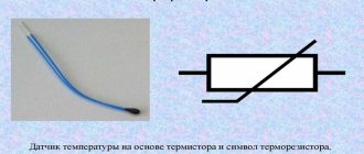
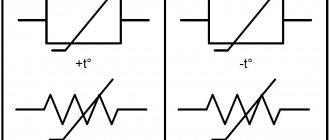
Thermistors or thermistors (TR) are semiconductor resistors with a nonlinear Volt-Ampere Characteristic (VAC). A characteristic feature of temperature-dependent resistors is that the resistance in the body of the element changes due to fluctuations in ambient temperature. Thermistors with negative and positive Temperature Coefficient of Resistance (TCR) are produced.Their scope of application is quite wide - they are used in circuits and temperature stabilization circuits of resistor amplifier systems, as well as in various types of devices and instruments for measurement, regulation and automation (measurement, level control and automatic adjustment of climate (temperature) and fire alarms).
The main characteristics of thermistors include:
- Nominal resistance Rн
- electrical resistance, the value of which is indicated on the case or indicated in the regulatory documentation, measured at a certain ambient temperature (usually 20°C). The values are set according to row E6 or E12.
- Temperature coefficient of resistance TKS
— characterizes a change (reversible) in resistance by one degree Celsius.
- Maximum permissible power dissipation Pmax
— the greatest power that a TR can dissipate for a long time without causing irreversible changes in characteristics. However, its temperature should not exceed the maximum operating temperature.
- Temperature sensitivity coefficient B
— determines the nature of the temperature dependence of this type of TR. Known as the “B constant”, it depends on the physical properties of the semiconductor material from which the temperature-sensitive element is made.
- Time constant t
— characterizes thermal inertia. It is equal to the time during which the resistance of a TR changes by 63% when it is transferred from an air environment with a temperature of 0°C to an air environment with a temperature of 100°C.
The dependence of the current that passes through the thermistor on the voltage applied to it (in the case of temperature equilibrium between the resistor and the environment) is determined by the current-voltage characteristic. Inertia shows how quickly the part will respond to changes in ambient temperature, that is, it determines the rate of change in the resistance of the element. Inertia is directly dependent on the design, size of the resistor and thermal conductivity of the environment. Stability determines the period of time during which an element retains its original properties (during use or storage).
| Range of nominal resistances at 20°C | Permissible deviation, ±% | Maximum power, at 20° C, mW | Operating temperature range, ° C | TCS at 20°С, %/°С | Constant V, K | Time constant t, s | Application area | Appearance | |
| Rod | |||||||||
| KMT-1 | 22 kOhm…1 MOhm | ±20 | 1000 | -60…180 | 4,2…8,4 | 3600…7200 | 85 | Temperature measurement and control, temperature compensation | |
| MMT-1 | 1 kOhm…220 kOhm | 600 | -60…125 | 2.4…5 | 2030…4300 | ||||
| CT3-1 | 680 kOhm…2.2 MOhm | ±10, ±20 | 3.35…3.95 | 2870…3395 | |||||
| KMT-4 | 22 kOhm…1 MOhm | ±20 | 650 | 4.2…8.4 | 3600…7200 | 115 | |||
| MMT-4 | 1 kOhm…220 kOhm | 560 | 2.4…5 | 3060…4300 | |||||
| CT3-6 | 6.8 kOhm, 8.2 kOhm | ±10 | 150 | -90…125 | 2.8…3.2 | 1200…2400 | 35 | ||
| MMT-6 | 10 kOhm…100 kOhm | ±20 | 50 | -60…125 | 2.4…5 | 2060…4300 | |||
| KMT-10 | 100 kOhm…3.3 MOhm | 250 for 2s | 0…125 | ≥4,2 | ≥3600 | 75 | Thermal control | ||
| KMT-11 | 10 | ||||||||
| C9T-1a | 150 Ohm…450 Ohm | 800 | -60…100 | 1600…2000 | 110 | Temperature regulation | |||
| Disk | |||||||||
| CT1-2 | 82 Ohm, 91 Ohm, 100 Ohm, 110 Ohm | ±5 | 700 | -60…85 | 4,4…4,9 | 3800…4200 | 60…100 | TK, temperature measurement and control | |
| CT4-2 | 2.1 kOhm…3.0 kOhm | -60…125 | 4,2…4,8 | 3170…4120 | Temperature measurement | ||||
| CT4-15 | 880 Ohm…1.12 kOhm | -60…155 | 3,4…3,8 | 2350…3260 | |||||
| KMT-8 | 100 Ohm…10 kOhm | ±10, ±20 | 600 | -60…70 | 4,2…8,4 | 3600…7200 | 900 | Temperature compensation | |
| MMT-8 | 1 Ohm…1 kOhm | 2,4…4 | 2060…3430 | ||||||
| MMT-9 | 10 Ohm…4.7 kOhm | 900 | -60…125 | 2,4…5 | 2060…4300 | ||||
| KMT-12 | 100 Ohm…10 kOhm | ±30 | 700 | 4,2…8,4 | 3600…7200 | TK, temperature measurement and control | |||
| MMT-12 | 4.7 Ohm…1 kOhm | 2,4…4 | 2060…3430 | ||||||
| MMT-13 | 10 Ohm…2.2 kOhm | ±20 | 600 | 2,4…5 | 2060…4300 | 100 | |||
| KMT-17v | 330 Ohm…22 kOhm | ±10, ±20 | 300 | -60…155 | 4,2…7 | 3600…6000 | 30 | ||
| CT1-17 | -60…100 | ||||||||
| CT3-17 | 33 Ohm…330 Ohm | 3,0…4,5 | 2580…3860 | ||||||
| CT4-17 | 1.5 kOhm…2.2 kOhm | ±10 | 500 | -80 … 100 | 3,8…4,2 | 3260…3600 | |||
| CT3-23 | 2.2 Ohm…4.7 kOhm | ±10, ±20 | 0 … 125 | 3,1…3,8 | 2600…3200 | TK | |||
| CT3-28 | 150 Ohm…3.3 kOhm | ±20 | -60 … 125 | 3…4,6 | 2580…3970 | ||||
| MMT-15 | 760 Ohm…1.21 kOhm | 2,6…4 | 2230…3430 | TK, temperature measurement and control | |||||
| PT | 80 Ohm…400 Ohm | ±20 | -60 … 150 | 4,4…4,8 | 3800…4100 | temperature measurement and control | |||
| PT-2 | |||||||||
| PT-1 | 400 Ohm…900 Ohm | 4,1…5,1 | 3500…4400 | Automatic control system sensors | |||||
| PT-3 | ±20 | 4,3…4,8 | 3700…4100 | ||||||
| PT-4 | 600 Ohm…800 Ohm | 4,4…4,9 | 3500…4200 | ||||||
| TR-3 | 1.2 kOhm, 12 kOhm | ±10 | 1000 | -60…125 | 3,9…4,8 | 3470…4270 | |||
| Beaded | |||||||||
| KMT-14 | 510; 680; 910 Ohm; 160; 200; 330 kOhm; 4.3; 7.5 MOhm at 150°C | ±20 | 100 | -100…300 | 2,1…2,5 | 3690…4510 | 10…60 | Temperature measurement and control | |
| 3,4…4,2 | 6120…7480 | ||||||||
| 3,5…4,3 | 6300…7700 | ||||||||
| CT3-14 | 1.5; 2.2 kOhm | 30 | -60…125 | 3,2…4,2 | 2600…3600 | 4 | |||
| MKMT-16 | 2.7; 5.1 kOhm | ±30 | 40 | -60…125 | 3,8…4,2 | 3260…3600 | 10 | ||
| CT1-18 | 1.5; 2.2; 22; 33 kOhm; 1.5; 2.2 MOhm at 150°C | ±20 | 45 | -60…300 | 2.25…5 at 150°C | 4050…9000 | 1 | ||
| CT3-18 | 680 Ohm…3.3 kOhm | 15 | -90…125 | 2,6…4,1 | 2250…3520 | ||||
| CT1-19 | 3.3…10; 100; 150 kOhm; 1.5; 2.2 MOhm at 150°C | 60 | -60…300 | 2.35…4 at 150°C | 4230…7200 | 3 | |||
| CT3-19 | 2.2; 10; 15 kOhm; | 45 | -90…125 | 3,4…4,5 | 2900…3850 | ||||
| CT3-22 | 1 kOhm at 25°C | ±30 | 8 | -60…85 | 3,1…4,2 | 2700…3700 | 15 | Variable resistance without moving contact | |
| CT3-25 | 1.5…6.8 kOhm | ±20 | -100…125 | 3,05…4,3 | 2600…3700 | 0,4 | Measurement | ||
| CT4-16 | 10…27 kOhm | ±5; ±10 | 150 | -60…155 | 3,45…4,45 | 2720…3960 | 30 | Temperature measurement, TC | |
| CT4-16a | 6.8; 10; 15 kOhm | ±1; ±2; ±5 | 180 | -60…200 | 4,05…4,45 | 3260…4100 | |||
| TR-1 | 15; 33 kOhm | ±10; ±20 | 20; 50 | -60…155 | 3,8…4,4 | 3200…3900 | 5…10 | ||
| TR-2 | |||||||||
| TR-4 | 1 kOhm | ±20 | 70 | -60…200 | 1,8…2,2 | 1600…1960 | 3 | Temperature measurement and control, TK | |
| Thermistors with negative TCR based on a semiconductor single crystal of synthetic diamond | |||||||||
| Type | Range of nominal resistances at 20°C | Permissible deviation, ±% | Maximum power, at 20° C, mW | Operating temperature range, ° C | TCS at 20°С, %/°С | Constant V, K | Time constant t, s | Application area | Appearance |
| TRA-1 | 0.01…10000 kOhm | ±5; ±10; ±20 | 500 | -200…+350 | 0,2…2,3 | 300…2500 | 1 | Measurement of temperature, liquid or gas flow rate, TK | |
| TRA-2 | 1…100 MOhm | 0,55…6,0 | 600…6000 | ||||||
| Thermistors with negative TCR - microwave power meters | |||||||||
| Type | Resistance at the main operating point, Ohm | Maximum power, mW | Operating temperature range, ° C | Sensitivity at operating point, Ohm/mW | TCS at 20°С, %/°С | Constant V, K | Time constant t, s | Appearance | |
| T8D | 140…160 | 15 | -60…85 | 20…30 | 1500 | 1 | |||
| T8E | 10 | 30…70 | — | ||||||
| T8M | 180…220 | 11 | 60…110 | — | — | ||||
| Т8Р | 115…135 | 12 | 10…19 | — | |||||
| Т8C1 | 110…130 | 24 | 10…40 | — | — | ||||
| Т8C2 | 140…160 | 19 | 12…25 | — | — | ||||
| Т8C3 | 140…160 | 23 | 10…50 | — | — | ||||
| T8S1M | 110…130 | 24 | 10…40 | — | — | ||||
| T8S2M | 140…160 | 19 | 12…25 | — | — | ||||
| Т8S3М | 140…160 | 23 | 10…50 | — | — | ||||
| T9 | 115…135 | 19 | 10…40 | — | — | ||||
| TS-1 | 150 | 12 | — | 0,6…3,4 | 0,8 | ||||
| TS-2 | 17,5 | — | 0,3…2,3 | 1,3 | |||||
| CT3-29 | 2.2 kOhm at 20°C, 200 when hot | 31 | 10…16 | 3,15…3,85 | 2700…3300 | 0,6…0,7 | |||
| CT3-32 | 2.2 kOhm at 20°C, 150 when hot | 18,6 | -60…70 | 20…30 | |||||
Note: The sensitivity of the TP at the operating point at an ambient temperature of 20°C is understood as the change in the resistance of the TP when the dissipated power changes by 1 mW.
| Thermistors of direct heating - voltage stabilizer | |||||||
| Type | Rated voltage, V | General voltage stabilization limit, V | Maximum permissible voltage change, V | Average operating current, mA | Current working area, mA | Maximum permissible short-term (2 s) overload, mA | Appearance |
| TP 2/0.5 | 2 | 1,6…3 | 0,4 | 0,5 | 0,2…2 | 4 | |
| TP 2/2 | 2 | 0,4…6 | 12 | ||||
| TP 6/2 | 6 | 4,2…7,8 | 1,2 | ||||
| Thermistors with negative TCS of indirect heating | |||||||||
| Type | Nominal resistance range | Rated power, mW | Operating temperature range, ° C | TCS at 20°С, %/°С | Maximum current in the heating circuit, mA | Constant V, K | Time constant t, s | Application area | Appearance |
| TKP-20 | 500 Ohm | 220 | -65…85 | 40 | 45 | Adjustable non-contact resistors | |||
| TCPM-20 | |||||||||
| TKP-50 | 2500 Ohm | 200 | 35 | 79 | |||||
| TCPM-50 | |||||||||
| TKP-300A | 10 kOhm | 24 | — | 20 | — | 17 | |||
| TCPM-300A | |||||||||
| ST1-21 | 6.8 kOhm - 150 kOhm | 60 | 3,25…5,75 | 25 | 2880…4920 | 15…40 | |||
| ST3-21 | 2,9…4,6 | 2560…3840 | |||||||
| ST1-27 | 680 Ohm - 1.5 kOhm | 70 | 4,3…5,25 | 27 | 3690…4510 | 4…6 | |||
| ST3-27 | 3…4,45 | 26 | 2560…3840 | ||||||
| ST1-30 | 33 kOhm | — | 4,2…5,1 | 120 | 3600…4400 | 6…12 | Measuring velocities of liquids and gases | ||
| ST1-31 | 4.7 kOhm | 194 | — | 44 | 3690…4510 | Adjustable non-contact resistors | |||
| ST3-31 | 680 Ohm | 90 | 3,15…3,85 | 29,1 | 2700…3300 | 4…6 | |||
| ST3-33 | — | 3…4 | 2790…3410 | 4…10 | |||||
| Thermistors with positive TCS - posistors | |||||||||
| Type | Range of nominal resistances at 20°C | Maximum power, W | Operating temperature range, ° C | TCS at 20°С, %/°С | Maximum current in the heating circuit, mA | Multiplicity of measurement in the area of positive TCS | Time constant t, s | Application area | Appearance |
| ST5-1 | 20…150 Ohm | 0,7 | -20…200 | 100…200 | — | — | 20 | Temperature measurement and control, fire alarm, thermal protection, current limitation and stabilization | |
| ST6-1A | 40…400 Ohm | 1,1 | -60…155 | 40…155 | — | 1000 at 25…140°С | |||
| ST6-1B | 180; 270 Ohm | 0,8 | -60…125 | 20…125 | — | 1000 at 25…100°С | |||
| ST6-3B | 1 - 10 kOhm | 0,2 | 10…125 | 15 | 100 at 25…80°С | 10 | |||
| ST6-4B | 100…400 Ohm | 0,8 | 20…125 | 1000 at 25…100°С | 40 | ||||
| ST6-4G | 5…25 kOhm | -20…125 | 2…6 | 5…15 | Temperature measurement and control | ||||
| ST11-1G | 100…300 Ohm | 6…9 | 20…80 | ||||||
| ST6-1B1 | 100…400 Ohm | -60…100 | 30…100 | 15 | 1000 at 25…100°С | 20 | Heating elements and temperature sensors, thermostatting. | ||
| ST6-2B | 10…100 Ohm | 1,3 | 10….100 | ||||||
| ST6-5B | 3…20 Ohm | 2,5 | -60…125 | 20…125 | 15 | 1000 | 10 | Current limitation and stabilization. | |
| ST6-6B | 5…25 Ohm | 180 | |||||||
| ST10-1 | 30…100 kOhm | 0,3…0,7 | -60…70 | -20…70 | 2…4 | 50 | TK | ||
| ST14-3 | 80…200 Ohm | 0,5 | -60…175 | 100…175 | — | — | — | Self-regulating heating elements of microwave devices | |
| ST15-2-127v | 15…35 Ohm | 3, Ulim=150V; I=24mA | -60…60 | 60…160 | 15 | 10000 at 25…160°С | — | In circuits for demagnetizing masks of color picture tubes | |
| ST15-2-220v | 20…50 Ohm | 3, Ulim=150V; I=12mA | -60…85 | ||||||
Description of the experimental setup
The current-voltage characteristics are measured according to the scheme shown in Fig. 3.
Fig.3. Electrical installation diagram
The measuring circuit is powered by a constant regulated voltage source with a built-in voltmeter. The current through the thermistor is measured with a milliammeter.
The MMT-4 thermistor is placed in a demonstration tube with terminals, which does not allow hot water to come into contact with the thermistor body; a liquid thermometer (it is advisable to use a mercury thermometer) can be installed in the tube to control the temperature, directly next to the thermistor.
Variable resistor R2 is only needed if an unregulated power supply is used.
Resistor MMT-4
The directory of precious metal content in radio components was created on the basis of reference data from organizations involved in the processing of scrap radio components, device passports, forms, labels and other open sources. It is worth noting that the actual content may differ by 20-30% downwards.
Content
Content of precious metals in the resistor: MMT-4
Gold: 0 Silver: 0.0150 Platinum: 0 MPG: 0 According to: Handbook of Precious Metals ORDER No. 70
Fixed resistors contain only silver, which is deposited on the terminals. With variable resistors everything is better, they can contain gold, silver, platinum and palladium alloys. Pretentious variable resistors are especially rich in precious metals.
The resistance of a resistor is its main characteristic. The basic unit of electrical resistance is the ohm (Ω). In practice, derivative units are also used - kiloohm (kOhm), megaohm (MOhm), gigaohm (GOhm). Precious metals are mainly found in variable and construction resistors, and palladium is often used in them in the form of runners or flux wires.
Types of resistors
There are three main types of resistors: A variable resistor is a resistor in which the electrical resistance between the moving contact and the terminals of the resistive element can be changed mechanically. Fixed resistors, the resistance of this resistor cannot be changed. As a rule, they have only two outputs. These resistors can only contain silver, in the form of silver-plated leads. Nonlinear. The resistance of components of this type changes under the influence of temperature (thermistors), light radiation (photoresistors), voltage (varistors) and other quantities.
Main characteristics of resistors
Nominal resistance (Ohm, kOhm, mOhm). Maximum power dissipation (0.25 W, 0.5 W, 1 W, etc.) Tolerance or accuracy class (the permissible spread of resistor parameters depends on this value).
Examples of alphanumeric designation of a resistor
Examples of alphanumeric designations for resistance expressed as an integer: 47 Ohm - 47 R; 47 kOhm – 47 K; 47 MOhm – 47 M. If a decimal fraction is used to express the resistance value, then the order of numbers and letters will be different, for example: 0.47 Ohm – R 47; 0.47 kOhm – K 47; 0.47 MOhm - M 47. If the resistance is expressed as a number other than zero and with a decimal fraction, then the letter in the designation plays the role of a comma, for example: 4.7 Ohm - 4R7; 4.7 kOhm – 4K7; 4.7 MOhm – 4M7. The permissible error is indicated in % and is indicated after the nominal value, for example ±7%, ±10%, ±40%. The accuracy class can be determined by a letter, depending on the manufacturer - Russian or Latin.
Share link:
Liked this:
Like
Similar
Work order
3.1. Removing the dependence of R(T) of the thermistor resistance on temperature. The thermistor is placed in a vessel with water, which is heated on an electric stove. Measure the resistance of the thermistor at different temperatures - from room temperature to a maximum of 90°C, with an interval of 10°C. Perform measurements for thermistors MMT-4 and MMT-1. Enter the results of the experiment into the table.
3.2. Determination of the thermal time constant of the thermistor. After measuring the resistance of the thermistor at 90 °C, quickly remove it from the water. Take the moment of extraction as t = 0. Turn off the thermostat.
While recording the time, measure the resistance of the thermistor as it cools until it increases approximately three times. Enter the measurement data into the table.
