Reversing a single-phase motor is an important part of its operation, which is widely used in a wide variety of systems with electric motors. We will look at how the rotor is started in the opposite direction, what back-turning is and how it is carried out at home.
AC induction motors are widely used in many industries that use electrical machines. Thanks to their high efficiency, simplicity of design and maintenance, such motors have occupied a strong energy niche. Moreover, they differ in the number of phases, which are influenced by the number of windings and many other factors. The most widely used are three- and single-phase motors, and the latter not only have a simplified operating principle, but are also capable of connecting to a 220 Volt network without any converters. In this article we will look at the principle of operation of a single-phase motor and how you can make it rotate in the fundamentally opposite direction.
Principle of operation
A single-phase asynchronous motor is a machine that has only one winding on the stator, which is powered by just one phase. In fact, even in the simplest design there are two windings, but the second acts as an auxiliary one and works exclusively when the engine is started, turning off during the process. Thus, the starting winding gives the rotor the necessary impulse, bringing the system out of balance - this is the simplest and most common way to push it.
The starting winding also differs from the working winding in size - it usually has half the number of slots. As in two-phase systems, both windings are located at right angles to each other. This allows you to generate the necessary force when starting work, then the starting phase is turned off, and then the engine maintains operation exclusively as a single-phase one.
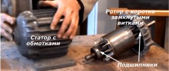
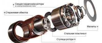
The design of the machine has a rotor and a stator, the first one must constantly rotate, and the second one must remain stationary. This is necessary to generate a magnetic field that will change over time. It is on the stator that the windings are located, while the rotor, through its rotation, ensures the operation of the entire mechanism. A single-phase motor has one of two types of rotors:
- short-circuited - also known as a “squirrel wheel”. It consists of a series of aluminum rods closed with rings at the ends;
- cylindrical - hollow inside, it is an empty cylinder.
Note that when the rotor rotates without using a starting winding, it enters a penetrating magnetic flux, which is generated by a pulsating field. If the system is at rest, then the rotor will not start in principle, since the total torque is zero, and both Ampere forces acting on the rotor completely compensate each other.
The situation changes if the rotor is pushed - it begins to move in the direction of the starting push. The law of electromagnetic induction begins to work, as a result of which the system generates corresponding currents in the direction of the push. However, the question arises: what determines its direction?
To do this, two factors need to be taken into account:
- placement of the starting winding relative to the rotor;
- phase shift of the current relative to the working winding.
If both factors satisfy the system parameters, then their combined action will be sufficient to generate a pulsating and rotating magnetic field. This sets the engine in motion, after which the starting phase is turned off, and then it operates on only one - it is enough to maintain the given rotation speed.
The bias in most cases is carried out using a special capacitor built into the system. Connected with the starting winding in a series circuit, it creates a phase shift of 90 degrees. From a technical point of view, the operator of the machine must press the button of the switch that supplies power to the circuit and release it only at the moment when the revolutions become equal to the corresponding rating indicated in the given frequency of the circuit.
Thus, for capacitor starting, reverse is carried out by creating a condition under which the push that starts the rotor is produced in the opposite direction than under normal conditions. This can be achieved if you correctly alternate the phases in both windings, which requires fine tuning. To do this, you need to switch the starting and working windings to change the overall polarity of the connection. You can perform a similar procedure manually by simply changing the terminals brought out. To understand which of them belongs to which winding, use a multimeter - a lower active resistance, which will help you find the working one.
Option 3: changing the starting winding to the working winding, and vice versa
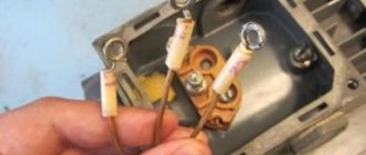
It is possible to organize the reverse of a single-phase 220V motor using the methods described above only if taps from both windings with all beginnings and ends come out of the housing: A, B, C and D. But there are often motors in which the manufacturer intentionally left them outside only 3 contacts. In this way, he protected the device from various “homemade products”. But still there is a way out.
The figure above shows a diagram of such a “problematic” motor. It only has three wires coming out of the housing. They are marked with brown, blue and purple colors. The green and red lines corresponding to the end B of the starting winding and the beginning C of the working winding are interconnected internally. We will not be able to access them without disassembling the engine. Therefore, it is not possible to change the rotor rotation using one of the first two options.
In this case, do this:
- Remove the capacitor from the initial terminal A;
- Connect it to the final terminal D;
- From wires A and D, as well as the phase, taps are made (you can reverse it using a key).
Look at the picture above. Now, if you connect the phase to tap D, the rotor rotates in one direction. If the phase wire is transferred to branch A, then the direction of rotation can be changed in the opposite direction. Reversing can be done by manually disconnecting and connecting the wires. Using a key will help make the job easier.
Important! The last version of the reversible connection diagram for an asynchronous single-phase motor is incorrect. It can only be used if the following conditions are met:
- The length of the starting and working windings is the same;
- Their cross-sectional area corresponds to each other;
- These wires are made of the same material.
All these quantities affect resistance. It must be constant at the windings. If suddenly the length or thickness of the wires differ from each other, then after you organize the reverse, it turns out that the resistance of the working winding will become the same as it was before for the starting winding, and vice versa. This may also cause the engine to fail to start.
Attention! Even if the length, thickness and material of the windings are the same, operation with a changed direction of rotation of the rotor should not be prolonged. This can lead to overheating and engine failure. The efficiency also leaves much to be desired.
Reverse the engine using the NVD button
In a broad sense, reverse means a change in the movement of the rotor in the opposite direction relative to its normal start. Note that this is a fairly important function that is necessary in the vast majority of systems. Reversing can be done in any type of electric motor, both asynchronous, running on alternating current, and for a motor running on direct current.
Since asynchronous motors, including single-phase ones, are used in most fields of activity and even in household appliances, reverse is a necessary function for performing basic mechanical actions. A striking example is lifting mechanisms that need to move in all directions, various locking devices of the “open-close” format and similar executive structures. For them, the need to reverse the rotor is constant, since its movement in both directions is a basic function, without which they will not be able to perform their duties.
Temporary reverse is not used very often, and is usually needed in emergency situations. For example, asynchronous motors installed in conveyors, escalators and pumps operate strictly in one direction. However, if the mechanism breaks or jams, reverse is activated, allowing you to stop or reverse the operation of the system.
Reverse is also used for sharp and rapid braking of the electric motor. In normal cases, the rotor continues to rotate even after the mechanism is disconnected from the network, since the inertia gained during operation is very reluctant to be spent. Thus, the motor operates even after the mains is turned off, which in some cases is extremely undesirable. A short-term start of reverse creates a counter-directional force that absorbs inertia, as a result of which the rotor can be stopped much faster than it stopped rotating naturally. In a professional environment, such a brake is called back-on.
Connecting a 220V motor to a single-phase network in reverse
In this case, it is possible to reverse the movement of the motor shaft if there is access to the terminals of its starting and operating windings. These motors have 4 outputs: two for the starting winding connected to the capacitor, two for the working one.
What kind of lighting do you prefer?
Built-in Chandelier
READ How to connect a Lenovo Tab 2 tablet to a computer via USB
If there is no information about the purpose of the windings, it can be obtained by dialing. The resistance of the starting winding will always be greater than the working winding due to the smaller cross-section of the wire with which it is wound.
In a simplified version of the motor connection diagram, 220 V is supplied to the working winding, one end of the starting winding per phase or network zero (it makes no difference). The engine will begin to rotate in a certain direction. To get a reverse circuit, you need to disconnect the end of the starting winding from the contact and connect the other end of the same winding there.
To obtain a complete working circuit diagram, you need the following equipment:
The reverse and forward circuit in this case is very similar to the connection circuit for a three-phase motor, but switching here occurs not of phases, but of the starting winding in one direction or the other.
What is the principle of reverse movement?
Since the operating principle of an alternating current electric motor is based on the rotation of magnetic fields in a certain direction, then to change it you will have to change the magnetic fields. The very principle of reverse operation is incredibly simple - you need to swap the wires responsible for the main rotation and launch. Since each of them is connected to both positive and negative, changing the wire completely inverts the polarity of the magnetic field. In turn, this means that it will begin to move in the opposite direction, dragging the rotor along with it, and with it the entire system in principle.
How to change rotation on a commutator motor.
- Physical change in the installation location of the brushes. This is irrational, since it is associated with the need to make changes to the design of the device. In addition, it leads to premature failure of the brushes, since the shape of the groove at their working end does not coincide with the shape of the commutator surface.
- By changing the position of the jumper between the brush assembly and the excitation winding in the terminal box, as well as the connection point of the power cable. Can be implemented using one multi-position switch or two magnetic starters.
Reverse circuit - implementation in practice
In order for the rotor to start rotating in the opposite direction, it is necessary to swap the second and third phases. Note that at first it will continue to move in the original direction by inertia, and only after some time it will enter a state of equilibrium, from which it will change direction.
The polarity of the starting winding, necessary to set the direction, can be done according to the circuit using a special control toggle switch. First of all, it must be selected based on the permitted motor voltage and current load, as well as the required fixed positions - 2 or 3. The current to the toggle switch should be drawn from the starting winding, since it does not work for so long and generally saves resources. This way you can reduce the cost of maintaining the entire system and the contact group in particular.
Experts advise reversing an asynchronous motor as follows:
- if the start-up is expected to be difficult, then it can be simplified with the help of an additional capacitor. This is only relevant for schemes that use a self-resetting NVD connection. Then the reverse toggle switch will turn on only if the rotor is braked, but not during operation, increasing the efficiency and stability of the system;
- The seat of the toggle switch for reverse must be protected from accidental operation. Since this is accompanied by huge current surges, this will save energy and engine life;
- if the mechanism does not reverse as required, then after connecting you need to check that the wires are connected correctly - often the terminals are confused and the whole circuit gets confused. Also, performance depends on the integrity of the wiring.
Given the fact that even the smallest problems can lead to reverse failure, it is important to thoroughly check the entire mechanism before starting it up. This will allow you to avoid breakdowns and emergency situations.
Subscribe to the newsletter
In order for mechanisms in production or at home, be it wood or metalworking machines, a cantilever pump, a conveyor belt, a crane beam, a sharpening machine, an electric lawn mower, a feed chopper or another device to work without breakdowns, it is necessary, first of all, for the electric motor shaft to rotate in the right direction.
In order to avoid mistakes and prevent rotation of the mechanism shaft in the opposite direction, in accordance with paragraph 2.5.3 of the “Rules for the technical operation of consumer electrical installations,” arrows in the direction of rotation of the electric motor .
Motor shaft rotation direction
The direction of rotation of the electric motor is determined from the single end of the shaft. If the engine has two shaft ends, then rotation is determined from the side of the shaft, which has a larger diameter. According to GOST 26772-85, the right direction corresponds to clockwise shaft movement. For the most common three-phase motors with a squirrel-cage rotor, the shaft will rotate to the right if the sequence of phases through which voltage is supplied to the ends of the stator windings corresponds to the alphabetical sequence of their markings - U1, V1, W1.
Right hand rotation
For single-phase motors with a squirrel-cage rotor, the shaft will rotate clockwise when the phase is supplied to the end of the working winding.
Changing the direction of shaft rotation in three-phase electric motors
The operation of some mechanisms requires left-hand rotation of the shaft. Knowing how to change the direction of rotation of an electric motor , this can be done without any modification or alteration of the drive motor itself. To change the direction of movement you need:
- de-energize the electric motor;
- remove the terminal box cover;
- rearrange the cores of the power cable in accordance with the diagram shown in Fig. 3: reconnect the black insulated wire (L3) to pin V1 in the terminal box, and reconnect the brown wire (L2) to pin W1.
Left-hand rotation
If the operation of the engine requires constant switching of the engine from right-hand rotation to left-hand rotation, its connection is carried out according to a special circuit,
Reversing a single-phase electric motor
You can start the rotation of a single-phase asynchronous electric motor by reconnecting the phase to the beginning of the working winding.
Knowing how to change the direction of rotation of an electric motor, you can connect a single-phase electric motor with the ability to switch from right-hand rotation to left-hand rotation using a three-pin switch.
Commutator single-phase motors and their features
A single-phase motor is the most common motor in household conditions, which is often reproduced with one’s own hands. The reason for this lies in the single-phase 220V network supplied to most workshops, houses and private plots. However, before starting work, it is important to determine what type of motor you have in front of you - commutator or asynchronous. In most situations, there are markings on the mechanism, but if it came into your hands after repair or reconstruction, then it would be safer to pay attention to the presence of brushes in the mechanism, located near the commutator, as well as a copper drum, which is divided into equal sections.
Commutator motors are exclusively single-phase and are very common in household appliances. Among their advantages it is worth highlighting:
- quick start - immediately after the electricity is supplied, the motor begins to accelerate at a high number of revolutions;
- Convenience of reverse - thanks to the system, it is not difficult to reverse the rotor movement in the opposite direction. To do this, you need to change the polarity of the magnetic field;
- rotation speed adjustment - by changing the voltage amplitude and cutoff angle, you can control the intensity of the rotor.
For these reasons, commutator motors are used in household and construction equipment. However, they also have a number of disadvantages:
- high noise - when reaching high speeds, the engine begins to make a lot of noise. This smooths out at low rotations, but not as often;
- difficulty of maintenance - the commutator motor must be checked and cleaned regularly. Graphite from erasable brushes contaminates the current collector and disables the entire system.
We have already discussed the structure and principle of operation of asynchronous motors above. Unlike collector engines, such engines operate almost imperceptibly even at high speeds. Therefore, they are used in equipment that is critical to have low noise limits during long-term operation - for example, refrigerators, air conditioners and climate control systems.
General features of the part
Among the key parameters evaluating the motor shaft, it is worth highlighting the diameter and free reach length. The last indicator determines the part that is located outside the housing and transmits torque.
Visually, the shaft has the shape of a steel rod, along its entire length with different diameters. In the middle of the magnetic drive is the thickest part of the shaft, because it accounts for the lion's share of all engine loads. Next come elbows with smaller diameters, including bearings of dimensions corresponding to the calculations of the output ring indicators.
The exact diameter indicator directly depends on the upcoming conditions and load levels that are pre-set to the electric motor during manufacturing.
Reverse capacitor motor
Due to the peculiarities of the mechanism, the capacitor engine only activates reverse if there are capacitors present. If you exclude them from the system, the motor will turn on, but the start will not occur, since sufficient force is not generated to start.
The first circuit includes a capacitor installed in the starting winding power circuit. Having an excellent start, such a mechanism greatly sags in power, which turns out to be below the nominal. The second connection scheme operates in the opposite way - by connecting a capacitor to the working winding circuit, you get a relatively difficult start, but the performance characteristics remain at a high level. Thus, both circuits find their application in different conditions - the first is needed for devices with heavy starting, and the second in devices that vitally require performance.
The third option involves installing two capacitors at once. This option is most often chosen, since it takes the best of both schemes - an excellent start and decent performance, but in return it requires more careful setup, regular maintenance and a special PVS button. During operation, both windings, both starting and working, remain active, and the first, even when turned off, continues to operate through the capacitor.
The key point in implementing reverse using capacitors is their correct choice. To correctly calculate their characteristics, experts use a complex formula with several variables. However, in practice everything turns out to be simpler if you follow a couple of recommendations:
- for the working capacitor, you should choose characteristics in the region of 70-80 μF per 1 kW of total engine power;
- for a starting capacitor, such indicators should be 2 or even 3 times higher;
- The capacitor voltage must exceed the mains voltage by at least one and a half times. For example, for a standard single-phase network of 220 V, you should select a capacity of 330, 380 V or more.
Note that there are specialized capacitors on the electronics market that were originally designed for starting. They are marked accordingly and provide a smooth start.
Subscribe to the newsletter
In order for mechanisms in production or at home, be it wood or metalworking machines, a cantilever pump, a conveyor belt, a crane beam, a sharpening machine, an electric lawn mower, a feed chopper or another device to work without breakdowns, it is necessary, first of all, for the electric motor shaft to rotate in the right direction.
In order to avoid mistakes and prevent rotation of the mechanism shaft in the opposite direction, in accordance with paragraph 2.5.3 of the “Rules for the technical operation of consumer electrical installations,” arrows in the direction of rotation of the electric motor .
Motor shaft rotation direction
The direction of rotation of the electric motor is determined from the single end of the shaft. If the engine has two shaft ends, then rotation is determined from the side of the shaft, which has a larger diameter. According to GOST 26772-85, the right direction corresponds to clockwise shaft movement. For the most common three-phase motors with a squirrel-cage rotor, the shaft will rotate to the right if the sequence of phases through which voltage is supplied to the ends of the stator windings corresponds to the alphabetical sequence of their markings - U1, V1, W1.
Right hand rotation
For single-phase motors with a squirrel-cage rotor, the shaft will rotate clockwise when the phase is supplied to the end of the working winding.
Changing the direction of shaft rotation in three-phase electric motors
The operation of some mechanisms requires left-hand rotation of the shaft. Knowing how to change the direction of rotation of an electric motor , this can be done without any modification or alteration of the drive motor itself. To change the direction of movement you need:
- de-energize the electric motor;
- remove the terminal box cover;
- rearrange the cores of the power cable in accordance with the diagram shown in Fig. 3: reconnect the black insulated wire (L3) to pin V1 in the terminal box, and reconnect the brown wire (L2) to pin W1.
Left-hand rotation
If the operation of the engine requires constant switching of the engine from right-hand rotation to left-hand rotation, its connection is carried out according to a special circuit,
Reversing a single-phase electric motor
You can start the rotation of a single-phase asynchronous electric motor by reconnecting the phase to the beginning of the working winding.
Knowing how to change the direction of rotation of an electric motor, you can connect a single-phase electric motor with the ability to switch from right-hand rotation to left-hand rotation using a three-pin switch.
DIY reversible connection of a single-phase asynchronous motor
Before choosing a connection diagram for a single-phase asynchronous motor, it is important to find out whether to reverse it. If for real work you will often need to change the direction of rotation of the rotor, then it is advisable to organize reversal with the introduction of a push-button station. If one-sided rotation is enough for you, then the most common scheme without the ability to switch will do. But what should you do if, after connecting via it, you decide that the direction still needs to be changed?
Reversing circuits for a single-phase asynchronous motor without opening the housing
If you don’t want to interfere with the system of an automatic asynchronous motor, and for one reason or another there is no access under the housing, you can use one of three fairly simple reverse methods.
Reconnecting the working winding
We have already discussed a similar connection diagram above - it is used most often due to its simplicity. It does not require opening the housing or turning over the winding - it is enough to simply reconnect the terminals of the working wires so that the phase moves from the initial to the final contact, and zero - vice versa.
Reconnecting the starting winding
The system is the same as in the previous version, but with the difference that the wires will have to be changed at the starting winding. After reconnection, the rotor torque should also change.
Complete winding replacement
If you want to create a reliable connection, or the motor model is atypical (for example, with three wires instead of four), you should completely replace the winding. For this, a capacitor is used, which is connected to the final terminal, and reverse taps are launched from the wires. The advantage of this scheme is the fact that the reverse can be controlled if you connect the wires manually.
Option 1: reconnecting the working winding
To change the direction of rotation of the motor, you can only swap the beginning and end of the working (permanently on) winding, as shown in the figure. You might think that to do this you would have to open the case, take out the winding and turn it over. There is no need to do this, because it is enough to work with the contacts from the outside:
- There should be four wires coming out of the housing. 2 of them correspond to the beginnings of the working and starting windings, and 2 to their ends. Determine which pair belongs only to the working winding.
- You will see that two lines are connected to this pair: phase and zero. With the motor turned off, reverse the phase by changing the phase from the initial winding contact to the final one, and zero - from the final to the initial one. Or vice versa.
As a result, we get a diagram where points C and D change places with each other. Now the rotor of the asynchronous motor will rotate in the other direction.
conclusions
As you can see, reversing a single-phase motor is not something complicated - on the contrary, it is widely used in many systems and mechanisms as part of the operation of the engine. However, in cases where reverse rotation is not provided, you have to look for an alternative way to reverse the rotation. Depending on the design of the motor, this can be done without disassembling the entire mechanism. It is only important to carry out the work with great attention to detail and with knowledge of the matter, to draw a diagram so that problems and emergency situations do not arise in the future.
Formulation of the problem
Let's imagine that an asynchronous single-phase motor, already connected with the introduction of a starting-charging capacity, initially has a shaft rotation oriented clockwise, as in the picture below.
Let's clarify the fundamental points:
- Point A marks the beginning of the starting winding, and point B marks its end. A coffee colored wire is connected to the initial terminal A, and a greenish colored wire is connected to the final terminal.
- Point C marks the beginning of the working winding, and point D marks its end. A reddish wire is connected to the initial contact, and a blue wire is connected to the final one.
- The direction of rotation of the rotor is indicated by arrows.
We set ourselves the task of reversing a single-phase motor without opening its housing so that the rotor begins to spin in the other direction (in this example, against the movement of the clock hand). It can be solved using 3 methods. Let's look at them in more detail.