Electrician in the house
Encyclopedia about electricity from A to Z
Masters catalog
Find the best master or company in your city
Simple and extremely reliable device
Any electric motor is a device capable of converting electrical energy into kinetic energy, that is, rotational energy, which is transmitted through circuits to driven devices. Electric motors are used almost everywhere today. These devices, which have remained virtually unchanged over the past 150 years, can even be found in toothbrushes.
Today we will talk to you about single-phase AC electric motors, find out how they are designed and due to what forces they are driven.
- Basic information Operating principle of a single-phase motor
- Motor connection
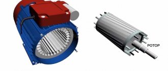
- Asynchronous motor
basic information
Synchronous single-phase AC motor powered by public network
So, a feature of a single-phase motor is that it can be powered from a standard electrical network with a frequency of 50 Hz and a voltage of 220 V.
- Such electric motors are installed mainly in low-power devices, since they are significantly inferior in efficiency to two-phase and three-phase analogues.
- The power of these units varies from 5 W to 10 kW.
- The single-phase motor connection circuit significantly affects its efficiency, which is approximately equal to 70% of the performance of a three-phase motor of the same power. They also have less starting torque and higher overload capacity.
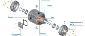
Electric motor cutaway
- In fact, if you look at the structure of such a motor, it will have 2 phases, but since, in fact, only one of them is used, it is called single-phase.
- The structure of the motor is very classic - a moving part (rotor or armature) and a stationary part (stator).
- The rotation of the moving parts of the engine occurs due to the interaction of magnetic fields - more on this a little later.
- The undoubted advantage of such a motor can be considered a simple and reliable design with a squirrel-cage rotor.
- And the main disadvantage can be considered the inability to independently generate a magnetic field, which does not allow it to start on its own when connected to the power supply.
- It is believed that in order for the rotor to start moving, at least 2 windings are required, as well as a displacement of one relative to the second by a certain degree.
AC induction motor
- If we compare all these points, we can understand the following.
- On the stator of a single-phase electric motor there is a starting winding, which is shifted relative to the working, main winding by 90 degrees.
- In the circuit feeding the winding, I include a phase-shifting device - capacitors, inductors, active resistors.
- That is, in fact, we are talking about the same motors of two- and three-phase types, only the phase shift is achieved not through connection, but through matching circuits.
Operating principle of a single-phase motor
Single Phase AC Synchronous Motor
Now let's try to systematize what we wrote in the previous chapter so that the principle of operation of such devices becomes clear to everyone.
How does a single-phase asynchronous electric motor work?
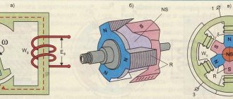
- So, when the power is connected, current begins to flow through the stator windings. The movement of current generates a pulsating magnetic field. Why is it pulsating, because the current in public networks has a frequency of 50 Hz, that is, it changes the direction of its movement 50 times per second. The magnetic field parameters change accordingly
- We all know about such a phenomenon as electromagnetic induction. If someone doesn’t know, then run to read - in short, this phenomenon generates an electric current in a conductor, which moves across a magnetic field, and there is no difference what will move - the conductor or the field.
- If the device does not have triggers, then the rotor will remain motionless, since there is still no current in it, and therefore no magnetic field, and the magnetic fields from the current in the stator are equivalent, and pull, so to speak, in different directions, like a swan , crayfish and pike.
- But if the rotor is given a push in any direction, the electromotive force (EMF) will instantly begin to grow in it, which will begin to generate its own magnetic field. As a result of the interaction of these fields, the engine will continue to rotate in the same direction, despite the fact that the main magnetic field is constantly changing its direction.
Single-phase AC commutator motor - operating principle
- The starting winding, which we have already mentioned, forces the rotor to move. What makes this more precise is the resulting magnetic field from the main and starting windings.
- This winding requires switching on only when starting the motor.
Interesting to know! In low-power motors, the starting winding is short-circuited.
- The moment the starting winding turns on is associated with the start button - usually it must be held for several seconds until the engine begins to rotate at normal speed.
- When the contact on the button opens, the motor switches completely to single-phase mode.
- It is important to remember that the start-up phase is not intended to operate for a long time - usually its active time is about 3 seconds. If you try to exceed this value, the winding will begin to overheat, which can lead to failure of the element.
- It becomes clear that manual control of engine starting is ineffective and unreliable, so this process is automated in modern devices. Thermal relays and centrifugal switches are installed in them.
- The first element controls the heating of both windings and turns off the power if the temperature reaches a critical value.
- The second turns off the power to the starting phase as soon as the rotor accelerates to the required speed.
Motor connection
How to connect a commutator single-phase AC motor
So, we have already realized that to operate such a motor requires only one phase of 220 V, that is, it is plugged into an ordinary outlet, which, in fact, makes these devices so popular despite the low efficiency and other disadvantages.
Interesting to know! Almost all household appliances are equipped with just such motors.
Various connection options
- Single-phase AC motors are divided into three types by connection: a version with a starting winding and a working capacitor.
- In the first, the starting winding is powered through a capacitor only during start - in fact, we described it in the previous chapter.
- In the second, it is permanently connected through a capacitor.
- The third uses a resistor instead of a capacitor.
Commutator single-phase AC motor from a washing machine
- For the last type of connection, a starting resistor can be used, which is connected to the starting winding in series. Due to this, it is possible to obtain a phase shift of 30 degrees, which is quite enough to spin up the engine.
- Also, the additional winding itself may have high active resistance.
- A phase shift can also be achieved by making the starting phase have high resistance and lower inductance.
Capacitor starting has the following features:
- To achieve the maximum starting torque sufficient to start the engine, you need a rotating circular magnetic field. This occurs when the windings are shifted relative to each other by 90 degrees - it immediately becomes clear that neither the resistor nor the inductor can set such a value. But if you choose the right capacitance of the capacitor - well, you understand...
- The capacitor must be selected based on current consumption.
Capacitor and alternating current
Interesting to know! On our website there is a very informative article about how capacitors behave in an alternating current circuit. If interested, be sure to check it out.
By the way, if you are trying to connect such a motor to the network yourself, but do not know which terminals belong to which winding, just measure their resistance. For the main one it will be about 12 ohms, and for the starting one - 30.
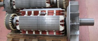
Structure of an asynchronous single-phase motor
Single Phase AC Brushed Motor
So, in the first part of the article, we discussed the general concepts about single-phase motors, the principle of their operation and connection. Such information would be enough for a superficial study, but we are not entirely satisfied with this approach. For lovers of technical details, let's now look at everything in more detail.
Asynchronous motor
Electric motors are either synchronous or asynchronous. The difference between them is that in synchronous, the speed of rotation of the armature coincides with the rotation of the magnetic field, while in asynchronous the rotor lags somewhat behind.
- The last option is the most common, as it has a simpler design and is very reliable. Synchronous ones are used only in those areas where control of engine speed is very important.
- You have probably already noticed that the word phase refers to different concepts - the number of supply wires, the windings on the stator, and the angular shift. And we even said that single-phase motors actually have two phases, but they are called such precisely by the number of supply wires.
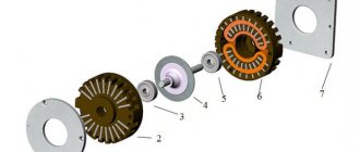
- We also wrote that the motor has moving and fixed parts. Let's look at their structure in more detail.
Single-phase AC commutator motors
- The rotor of the unit is a shaft that is supported in the engine housing using rotation bearings. Due to them, it rotates freely around its axis. The structure of this element will differ depending on whether the engine is brushed or brushless. Let's start with the second one.
- A magnetic circuit is fixed to the shaft of the brushless phase rotor, which is assembled from laminated steel plates.
- On the outside of the magnetic circuit there are grooves in which the winding rods are located - usually made of copper.
Motor with phase-type rotor
- At the ends, the rods are connected to rings that short-circuit them - they are called closing rings.
Structure of a wound rotor
- A current will flow inside this winding, which is induced by the magnetic field of the stator - it has no external connections.
- The magnetic core serves for better passage of the magnetic field that is created in the rotor.
- Such devices are characterized by high reliability, since they do not have rubbing parts. The motor rotation speed is controlled only by the current on the main stator winding.
- A single-phase AC commutator motor is not much different in structure from the rotor of a DC motor. Actually, such motors are universal and can be powered by both alternating and direct current.
- The rotor phases are connected to the power supply through a commutator, which is in contact with the brushes, which in turn are already connected to the supply circuit.
- The structure of such engines is more complex, and their reliability will also be lower, but they are more flexible in control.
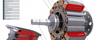
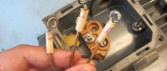
In the photo - the stator of the electric motor
- The stator is the passive part of the electric motor - it is motionless and consists of a magnetic core and winding.
- The purpose of this element is to generate a stationary or rotating magnetic field.
- A single-phase motor will have four terminals coming from the stator - two for the working winding and two for the starting winding. We have already written how to distinguish them.
In addition to these elements, the engines have the following components:
- The frame and body of the device , which hold all the working parts and allow you to fix the device on the surface;
- External electrical circuit - power button, speed control device, wires and devices for bypassing the additional winding;
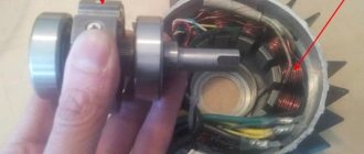
- Impeller – active cooling of the engine, also located on the shaft;
- Rotation bearings.
Layout and operating principle
The moving part of a commutator motor, like any other, is mechanically balanced and secured in rotation bearings mounted in a stationary frame.
The stationary stator and rotating rotor have their own windings made of insulated wire. An electric current flows through them, creating magnetic fields with their own poles: north N and south S.
The interaction of these two electromagnetic fields creates rotation of the rotor.
Since voltage must be constantly supplied to both windings, and the rotor rotates, a special device is mounted for it: a commutator with a brush mechanism.