In household appliances, hand-held power tools, automotive electrical equipment and automation systems, a commutator AC motor is often used, the connection diagram of which, as well as the device, are similar to DC motors.
Their widespread use is explained by their compactness, low weight, low cost and ease of operation. In this segment, motors with high frequency and low power are most in demand.
Operating principle and design features
This device is quite specific, having, due to its similarity with DC machines, similar characteristics and inherent advantages.
The difference from DC motors is the material of the stator housing, made of sheets of electrical steel, due to which it is possible to reduce eddy current losses.
So that the engine can operate from a regular network, i.e. 220 V, field windings are connected in series.
These motors, called universal due to the fact that they operate on alternating and direct current, are single- and three-phase.
Video: Universal brushed motor
DIY reversible connection of a single-phase asynchronous motor
- directly from a three-phase network (in this case, you need to swap any two of the three phase wires);
- the electric motor is powered by a capacitor from a single-phase network (here we need to disconnect the output of the capacitor, which is connected to one of the wires that powers it, and then switch to the other);
- the electric motor is powered by a three-phase inverter (here it is better to trust the instructions for use).
Useful tips Connection diagrams Principles of operation of devices Main concepts Meters from Energomer Precautions Incandescent lamps Video instructions for the master Testing with a multimeter
What does the structure consist of?
The design of an AC electric motor includes, in addition to the rotor and stator:
- tachogenerator;
- brush-collector mechanism.
The armature current interacts with the magnetic flux of the field winding, causing rotor rotation in the collector mechanism. Current is supplied through the brushes to the commutator, which is the rotor assembly and is connected in series to the stator winding. It is assembled from plates with a trapezoidal cross-section.
The principle of operation of such an engine can be demonstrated using the well-known experiment from school with a rotating frame, which was placed between opposite poles of a magnetic field. It rotates under the influence of dynamic forces when current flows through it. When changing the direction of the current, the frame does not change the direction of rotation.
High idle speeds caused by the maximum torque when connecting the field windings in series can lead to failure of the mechanism.
Connection diagram (simplified)
A typical connection diagram provides for the output of up to ten contacts to the contact strip. The current L flowing through one of the brushes enters the commutator and armature, then passes to the stator windings through the second brush and jumper, leaving the neutral N.
This method of connection does not provide for reversing the motor, since connecting the windings in parallel leads to a simultaneous change in the poles of the magnetic fields. As a result, the direction of the moment is always the same.
We recommend:
It is possible to change the direction of rotation if you change the locations of the winding outputs on the contact strip. The motor is turned on directly when the rotor and stator outputs are connected to a brush-commutator mechanism. To turn on the second speed, the terminals of half the winding are used. We must not forget that from the moment of such connection the motor operates at maximum power, so its operation time cannot exceed 15 seconds.
Video: Connecting and adjusting engine speed from a washing machine
Methods for changing directions in a commutator motor with application diagrams
Most of the tools have a commutator motor. This is one of the common and affordable engines that has excellent characteristics. Actually, this, and even the low price, determines its significance.
Electric motors have become an integral part of people's lives, simplifying it and taking a lot of work on themselves. They provide the production of everyday and construction equipment and are represented by one of the auxiliary parts of production equipment.
What is a commutator motor and its features
The commutator is the engine element in contact with the brushes. This department guarantees the transfer of electricity to the working division of the unit. A chronic current commutator motor is a rotating direct current electrical apparatus that converts continuous current energy into machine energy, where one winding, which assists in the process of generating energy, is connected to a heat exchanger. Operates through a constant and intermittent flow of energy, power 300–800 W, number of armature turns 11,500–15,000 rpm.
Commutator electric motors are: direct and alternating current;
The latter are universal and operate both from a constant and from a replaceable flow. They remain popular even if they have brushes. Brushes are known to be not very convenient, as they wear out and spark. This element requires continuous monitoring and industrial maintenance.
The advantages of collector engines include the possibility of soft adjustment of speed over a wide range and low cost. Like other electric motors, the commutator motor consists of a stator and a rotor (often called the “armature”). Its distinctive feature is the existence of a collector unit on the shaft, through which power is transmitted to the machine. The mechanism of continuous and alternating current commutator motors is almost the same, but has some differences.
Continuous current commutator motor
The smallest engines of the provided type (units of Watt) are stored in the housing:
· three-pole rotor on plain bearings;
· collector section of 2 brushes, which are connected to each other with 3 copper plates;
· two-pole stator made of continuous magnets.
Such motors are mainly used in infant toys, music players, dryers, electric razors, cordless screwdrivers, etc. (working force 3-9 volts).
Engines of higher power (tens of watts) are respectively composed of:
· semi-polar rotor on bearings; collector unit of four graphite brushes;
· four-pole stator made of permanent magnets.
However, this consistency of the apparatus is used in most electric motors in new cars (working force 12 or 24 Volts): driving the propellers of cooling and ventilation systems, windshield wipers, and washer pumps.
Variable flux commutator motor
An alternating current commutator motor is a rather specific device, which has all the perfections of the long-term current mechanism and, regardless, is characterized by the same properties. The difference between these units is that the upholstery of the stator of an unstable current motor, to reduce costs in vortex energy, is made from separate sheets of electrical steel. The drive windings of the equipment are introduced one by one to optimize the output in a 220V household network.
There are also three-phase ones, whose ability to operate from direct and alternating current is also called universal data. Turning off the stator and rotor, the mechanism contains a brush-commutator apparatus and a tachogenerator. The circulation of the rotor in the commutator motor is determined by the joint performance of the armature flux and the magnetic current of the excitation winding.
By using a brush, the current is redirected to a heat exchanger organized from trapezoidal separation plates and is represented by one of the rotor units, alternately combined with the stator windings.
Product principle
The tool combines a fixed part, the stator, and a replaceable part, the rotor. Exciting windings are placed in the stator, the rotor monitors the transmission of the emerging machine force. Also part of the rotor is the shaft.
Actually, the principle of behavior does not differ from other engines; the rotor initiates turning in the magnetic sphere due to the currents induced on it. But how exactly and why are these currents induced? To understand, you need to remember how electromotive power is created in a constant magnetic field. If a rectangular frame is placed in the field of a continuous magnet, it begins to rotate under the influence of the current in it. The direction of rotation is determined by the gimlet rule. For a constant field, it says this: if you place your right hand in the field so that the magnetic outlines fit into the palm, the outstretched fingers will show the direction of movement.
How to change the movement in a commutator engine
The first of the current-collecting brushes is connected to the stator winding, and the feeding force is directed to the other brush and another cord of the stator winding. In order for the location of the plug in the socket to change, a synchronous change in the poles of the rotor and stator magnets occurs. Therefore, the course of rotation will not change. Moreover, as happens in a long-term current engine with a simultaneous change in the polarity of the supply force on the excitation and armature windings. Changing the “phase-zero” sequence must only be done on one element of the electrical machine - the collector, which guarantees both spatial and electrical separation of the wires - the armature coils are protected.
This can be done in a couple of ways:
· Manually changing the location of the brush design. This is rare, because it looks like changes have been made to the composition of the device. Moreover, the result will be early failure of the brushes, because the shape of the exhaust at their effective output will not be the same as the shape of the commutator plane.
· Replacing the location of the switch among the brush assembly and winding in the terminal box, and then the connection point of the power cable. It is possible to create with the power of one multi-position switch or a pair of magnetic starters.
How to smoothly change the course of rotation of a commutator engine
If you simply change the opposite of the input force on the commutator motor, the direction of rotation of the rotor will not change. In addition, you need to understand that in high power motors the armature winding will be switched. When switching the stator windings, a self-inductive force appears that reaches magnitudes that can eliminate the heart from functioning. The leads of the field winding must be swapped. When a third cord is present, it is not used.
It is not possible to implement reverse on every commutator motor; if a rotation indicator is directed in the housing, then it cannot be used in reversing devices. All high-turn motors are specialized to rotate in one direction. For example, in an electric motor that is used in grinders. With an engine that has low speeds, circulation is possible in different directions. The program for switching on its windings is similar to that on continuous current motors with sequential excitation.
In fact, the entire range of electric motors for domestic use, at home or in the country, simultaneous - commutator. Rarely can they be asynchronous. The commutator motor is used in washing machines to spin the drum, electric drills, and so on. Such motors are attached to the winding and do not move. In addition, this motor has a winding on the armature. The force from the commutator is directed to both of these windings. Repairing such an engine is cheap, but it is easy to implement at home. It just requires an understanding of the device and compliance with safety precautions. It is also advisable to check the connection keys for the operability of the device and the power cords. These characteristics can be examined using an indicator screwdriver or a multimeter.
Connection schemes
The standard connection method involves placing up to 10 contacts on a contact strip. The flow L flowing from the side of one of the brushes is arranged on the commutator and armature, then passes to the stator windings through the second brush and jumper, protruding into the neutral N. A similar connection method does not provide for motor reversal, since the synchronous connection of the windings leads to a simultaneous change of poles in the magnetic fields.
Consequently, the direction of the circumstance is always the same. It is possible to adjust the direction of rotation when you can change the outputs on the contact strip in places in the winding. The motor is connected cleanly if the rotor and stator wires are connected to the brush-commutator apparatus. To switch the second speed, only half-winding cords are used.
It is important to remember that from the factor of such inclusion, the heart of the instrument operates at its greatest power, therefore, its operating time should not exceed 15 seconds. Primitively, this method can be depicted with similar points:
· a command from the electrical circuit is served to the triac gate;
· the damper opens, the flow flows through the stator windings, activating the circulation of the motor armature M;
· instantaneous values of the torsion frequency are reorganized by the tachogenerator into electronic signals that create feedback with control pulses;
· In the final moment, the rotation of the rotor remains uniform at any strength;
· with the additional use of relays R and R1, the motor is reversed.
Rotation modification
Before “changing brushes” or other wires, take a closer look at how the brushes are adjusted in relation to the commutator. If the brushes are placed vertically to the surface of the cylinder, which forms the commutator, then it is possible to change the direction of rotation of the engine using any method, only two technologies: change the position of the wires among themselves, suitable for the brushes, or the wires that are installed to the excitation winding (stator). But when the brushes are not inserted vertically, it is not advisable to further change the direction of rotation. The rotor will spin, but there will be an increased generation of sparks and rapid wear of the brushes.
It is easy to inspect the design of the brushes: remove the brush and look at the section of the excavation; if it is symmetrical, the brushes are perpendicular, so vice versa. You can also listen to the sound produced by brushes when turning the heat exchanger manually - with an invariant installation, there will be one for any direction of rotation.
Collector motor speed regulator
If the alternating current motor is turned on at absolute power, current is transferred with the entire load power, which is repeated 7-8 times. This current bends the motor windings and produces heat that will be released for a long time. This can significantly reduce engine survivability. In short, a converter is a step inverter that guarantees a paired change of energy.
The recommended speed stabilizer is specialized for working in conjunction with commutator motors and is a completely analog device. The regulator has a feedback connection for the rotation frequency; it also does not require any additional tachogenerator devices. The most commonly known type of stabilizer for the circulation frequency of the main motor of cassette tape recorders is a stabilizer with positive flow feedback. The regulation is parametric, therefore, the harmonic is quite strongly modified when the overload on the motor shaft changes.
To improve the quality of work in the stabilizer, it is necessary to establish a feedback connection based on the rotation frequency. Given such data, it is normal to install a special sensor for the motor shaft. Mostly optical only. Such a converter contains an optocoupler, the optical flow is stopped by an impeller (or a disk with holes), and then it is mounted on the motor shaft. The impeller stops the optical flow, and at the end of the optocoupler, pulses are added with the motor rotation frequency raised by the sum of the slots in the impeller.
From time to time, another type of sensor is adapted - magnetic. When a gear made of ferromagnetic material is placed on the motor shaft, near which a head with a magnet is fixed. When the gear rotates at the head terminals, there is an unstable force with an amplitude of about a millivolt, and a frequency equal to the rotational frequency of the engine, raised by the sum of the teeth on the gear. This flow includes an unstable component, which includes a harmonic, which has a frequency equal to the engine circulation frequency, raised by the number of collector plates. Motors, which are more often used in tape recorders, have three collector plates. Therefore, this harmonic is equal to triple the engine rotation frequency. The regulator is built only on this principle.
How to choose a gearbox
There are quite a few characteristics that will help you select a regulator:
· Type of control. For commutator motors, there are regulators with a vectorial or scalar guidance system. The main ones are more often used, however, others are considered more reliable;
· One of the desirable factors when choosing a galvanic frequency converter. You need to choose a frequency driver with a power that corresponds to the maximum allowed on the protected instrument. But for a low-voltage motor, it is preferable to choose a stabilizer stronger than the permissible Watt value;
Of course, here everything is provided for each individually, but if possible, it is necessary to purchase a gearbox for the electric motor, whose basic circuit has a wide range of permissible voltages;
· Frequency coverage. Frequency conversion is the key theme of the provided unit, so try to find a type that will best suit your needs. Roughly, for the sake of a hand router, 1000 Hertz would be a pretty good figure;
· According to other criteria. This is the warranty period, the amount of inputs, coverage (for machines and hand-held devices there is a specific attachment). At the same time, it is still necessary to understand that there is a so-called comprehensive circulation stabilizer. This is a frequency unit for brushless motors.
Advantages and disadvantages of collectors
The advantages of commutator electric motors are:
· Elementary device.
· Noble speed up to 10,000 rpm.
· Good torque even at low speeds.
· Low cost.
· Possibility of coordinating haste over a wide area.
· Low initial fluids and loads.
In the rotor you can see that each winding is a similar frame. Only it consists not of one wire, but of several, but this does not change the essence. With the help of a collector unit, at some point in time, the coil is connected to pressure and a flow passes through it and a magnetic field is tied around the conductor. It cooperates with the stator field. It depends on the type, whether long-term magnets are used there or whether a non-stop current flows in the windings, creating its own magnetic field at the poles.
The rotor and stator apparatus are designed so that, with their assistance, they “push” the rotor in the desired direction. The more force is applied to the rotor windings, the stronger the powerful sphere the stator produces, the stronger their reaction and the faster the rotor turns because it is faced with enormous force. Also, with the method of reducing force, the interaction decreases, and so does the resulting speed of rotation. Therefore, everything you need to coordinate the voltage can be done using even a simple auto potentiometer (variable resistance).
Satisfactory qualities, but there are also disadvantages, and they are quite serious. The disadvantages of commutator electric motors are:
· High degree of hum when driving.
· Especially when exposed to high speeds.
· The brushes rub against the trimmer apparatus, resulting in noise.
· Brushes spark and wear out
· The need for periodic maintenance of the collector unit.
· Low stability of characteristics when the load changes.
· Increased failure rate due to the presence of a commutator and brushes, a short period of serviceability of this unit.
In general, the collector heart is a good choice; otherwise it would not be installed on household appliances. With normal operation, such motors function for years. They can work normally for 10-15 years without accidents.
Checking the commutator motor for damage
The most difficult task that can be done with such a device is disassembly. Oddly enough, a brushed motor is not easy to disassemble. It will take a long time to analyze the dismantling of the motor for all device options; it is preferable to determine a special manual naturally for your type of mechanism. It is important not to neglect safety precautions; all devices must be turned off during disassembly.
Take tools with insulating material. If the electric motor is dismantled, try applying voltage to it. If it works, but the sparks in the brushes have increased (the tails of the sparks when circling are uneven, at times they fit more than 90°), most likely, the time has come to replace them or adjust the attachment of the device.
An unstable connection may cause problems. This may also mean interturn bridging inside. Devices should only be replaced with ones that are the same as the previous ones. The brushes are generally secured with a retainer or bolts. Sometimes they are fixed on a special lever. When the brushes are normal, but poorly attached, it is imperative to attach the springs.
When the contacts on the device have darkened, you need to clean it. A good way is to use sandpaper with a light grit. When this method does not help, then the source of the failure may be wear of the bearings. Also, when too much noise or excessive vibration is noticeable, it is likely that the bearings need to be replaced.
When the unit cannot be turned on in any way, visually check the integrity of the windings and the absence of blackening. Burnt insulation must be cleaned; if graphite dust is present, everything must be thoroughly cleaned. The ashes cause a short circuit. All wiring must be tested with a multimeter. When the wrapping does not provide conductivity, it is possible that in this case the restoration of the unit will become more expensive than a new one.
Engine control
In practice, various methods of regulating engine operation are used. This can be an electronic circuit where the regulating element is a triac, which “passes” a given voltage to the motor. It works like an instantaneous key, opening when a control impulse is received at its gate.
The principle of operation implemented in circuits with a triac is based on full-wave phase control, where the voltage supplied to the motor is tied to the pulses that arrive at the electrode. In this case, the frequency with which the armature rotates is directly proportional to the voltage supplied to the windings.
Simplified, this principle can be described by the following points:
- a signal from an electronic circuit is supplied to the triac gate;
- the gate opens, current flows through the stator windings, causing the motor armature M to rotate;
- instantaneous rotation speed values are converted by the tachogenerator into electrical signals, forming feedback with control pulses;
- as a result, the rotation of the rotor remains uniform under any load;
- Using relays R and R1, the motor is reversed.
Another circuit is a phase-pulse thyristoran.
Reversing diagram of a three-phase motor and a push-button station
Each system that provides reverse of a three-phase electric motor has specific push-button contacts combined into a common push-button post. The operation of this system is closely related to the functioning of the remaining elements of the circuit.
Everyone knows that the magnetic starter contactor is turned on using a control pulse received after pressing the start button. This button primarily supplies voltage to the control coil.
The switched-on state of the contactor is maintained and maintained thanks to the self-retaining principle. It consists of connecting in parallel (bypassing) an auxiliary contact to the start button, which supplies voltage to the coil. In this regard, it is no longer necessary to hold the START button pressed. Thus, the magnetic starter can turn off only after the control coil circuit is broken, so the circuit requires a button with a break contact. In this regard, control buttons combined into a push-button station are equipped with two pairs of contacts - normally open (NO) and normally closed (NC).
Machine advantages and disadvantages
The advantages include:
- small sizes;
- versatility, i.e. work on constant and alternating voltage;
- high starting torque;
- independence from network frequency;
- speed;
- soft adjustment of rotation speed over a wide range when varying the supply voltage.
Disadvantages are also associated with the use of a brush-collector junction, which entails:
- reducing the service life of the mechanism;
- sparks occurring between the brushes and the commutator;
- high noise level;
- a large number of collector elements.
Basic faults
The sparking that occurs between the brushes and the commutator is the most important issue that requires attention. To avoid more serious malfunctions, such as peeling and deformation of the lamellas or overheating of the lamellas, a worn-out brush must be replaced.
In addition, a short circuit between the armature and stator windings is possible, causing strong sparking at the commutator-brush junction or a significant drop in the magnetic field.
To extend the service life of the engine, two conditions must be met - a professional manufacturer and a competent user, i.e. strict adherence to operating hours.
Video: Brushed electric motor
We are returning again to the world of entertaining things - like electrical engineering , because I think that we all simply need this knowledge in our daily lives.
Read also: How to determine cable cross-section by eye
Typical faults
The brush-commutator mechanism requires the greatest attention, in which sparking is observed even when the new engine is running. Worn out brushes should be replaced to prevent more serious problems: overheating of the commutator lamellas, their deformation and peeling. In addition, an interturn short circuit of the armature or stator windings may occur, which results in a significant drop in the magnetic field or strong sparking of the commutator-brush junction.
Premature failure of a universal commutator motor can be avoided by proper operation of the device and the professionalism of the manufacturer during the assembly process of the product.
Connecting a single-phase commutator motor - AC
In this topic, you need to understand exactly how a single-phase AC commutator motor is connected, for example, after it has been repaired. The electrical circuit in Fig. 1 gives us an idea of the nature of the electrical connections, that is, here we can notice that the two stator windings of the electric motor in the electrical circuit are in series connection, and the two rotor windings of the electric motor relative to the external voltage source are connected in parallel and the electrical circuit for this example, it is closed on the rotor windings of the electric motor.
Who among us analyzed household electricity consumers as:
and further, they will agree with me that for the electrical circuit in Fig. 1 one more element is missing - a capacitor. Therefore, to this name of the motor type you can also add the name capacitor electric motor. If you follow logical thinking, then the capacitor in the electric motor circuit is necessarily connected to the starting winding of the stator, which serves to initially shift the rotor. Accordingly, we came to the conclusion that the capacitor must be directly in series connection with the starting winding. For example, a diagram of a single-phase motor with working and starting stator windings is shown, where the resistance on each winding will take its own value (Fig. 2).
Depending on the types of asynchronous motors and their application (Fig. 3), there are the following connection diagrams to a single-phase network:
a) ohmic phase shift, bifilar method of winding the starting winding;
b) capacitive phase shift with a starting capacitor;
c) capacitive phase shift with a starting and running capacitor;
d) capacitive phase shift with a working capacitor.
The diagrams indicate the following designations:
Before connecting a commutator single-phase motor , it is necessary to determine:
stator windings. The capacitor, with its capacitance and voltage ratings, and the corresponding data for a particular type of motor, should be connected to the stator starting winding - in series. The resistance of the stator windings takes the following average values:
- working winding 10-13 Ohm;
- starting winding 30-35 Ohm;
- total winding resistance 40-45 Ohm,
- for some types of household appliances. By measuring the resistance at the wire terminals of the stator windings, you can determine the starting winding with its average value. That is, the resistance of the starting winding takes the average value between the working winding and the total resistance of the two windings - working and starting.
Reversing diagram of a three-phase motor in a single-phase network
Quite often, three-phase electric motors are used in domestic conditions and are connected to a single-phase network. For such cases, a reversible circuit for connecting an electric motor in a single-phase network is provided. The principle of operation of such a circuit is very simple: to perform reverse, capacitors are used, the power of which is switched between the poles of the supply voltage. The circuit is controlled by a button.
Since the supply voltage is 220 V, the motor windings will be connected as a star, and three terminals will be connected to the terminal block. On the control button, a jumper is installed between the terminals, after which the capacitor output is connected to one of them. The second terminal of the capacitor is connected to the winding of the electric motor, which is not connected to the network.
The switch is then connected to the motor, then the supply voltage is applied. The finished system needs to be turned on and the reverse operation checked.
Control of a commutator motor - without a rheostat
To control a commutator motor - without a rheostat, a packet switch is quite suitable, with the help of which the contact group is switched - in the switch Fig. 4.
In this example, depending on the switching position, the direction of rotation of the electric motor rotor will change, operation is carried out at a constant speed and engine speed, only the polarity of the stator windings changes.
cam packet switch
To control the rotation speed of the electric motor rotor, you can use a triac rotation speed controller. This electrical installation product, like all others, is selected taking into account the rated current and voltage values - the connected load and the power of the electrical energy consumer are taken into account.
The consumer power, as is clearly seen from the formula in Fig. 5, is the product of current and voltage. Why is it necessary to carry out preliminary calculations at all? The load, as we know, is connected through a residual current circuit breaker. To install and connect a residual current circuit breaker, take into account the calculation of the load current strength in Fig. 6.
triac motor speed controller
In short, to imagine what a triac regulator is, you again need to remember the basics of electronics. The triac, which is part of the control circuit, performs the function of a regulating element - to power the electric motor (Fig. 7).
The figure shows the conclusions of the triac:
When a pulse arrives at input G, the triac opens (Fig. 8), that is, it acts as an electronic key to power the electric motor.
The photograph shows an image of the electronic control module. An electronic control module is found in automatic washing machines operating in a preset, automatic mode.
Indesit washing machine electronic control module
Connecting a commutator motor - via a rheostat
This schematic diagram, Fig. 9, shows the connection of the load to the output terminals of the generator through a rheostat. The load here is an electric incandescent lamp. The rheostat in the electrical circuit is connected in series, the load light bulb is connected in parallel in the circuit. In the same way, instead of this load, you can connect a commutator motor powered by electrical energy sources, such as:
or from an external energy source, that is, from the electrical network. When connecting a commutator motor, you need to take into account the electrical diagram of the stator windings and the type of motor, as is permissible for the following diagram in Fig. 10.
The electrical circuit is a circuit of a universal commutator motor, where the motor can operate on both alternating and direct current.
At one time, I made a certain number of electric emery machines, electric motors were mounted on a platform and then connected, an attachment for installing an emery wheel was attached to the rotor shaft, therefore, in my practice I had to connect various types of electric motors.
Read also: Device for end drilling
The given example of electric emery sanders is a rather interesting and useful topic for our everyday needs.
It remains to wish you successful repairs for various types of household appliances.
The article was not written by a technically literate moron, a diagram of a brushless motor, but a description of a brushed motor and vice versa.
Hello electrician. What circuits do you mean with the names: “brushless and brushed motors”? The diagrams provide an explanation of the connection of the windings of the commutator motor. You do not need to introduce yourself as an electrician, but indicate your name. For example, I have a first name, patronymic and last name - Viktor Georgievich Povaga. I live in Siberia, I work under an agreement with Yandex.Direct. Next time, if you receive such a letter, I will contact the Internet company to search for you and then, before the court, you will prove “who I am.” All the best to you, “electrician.”
Victor Georgievich! Thank you very much for the useful article.
Hello. I don’t understand anything about electrics, but I need to connect the IP-22 DC electric motor to a regular network
Hello. In my practice, I have not seen this type of IP-22 electric motor. I don’t understand what you are talking about here - the IP-22 fire detector or the electric motor? Indicate the technical specifications for your electric motor and country of origin so that I can navigate your question.
Good afternoon, Victor! Tell me, will a triac converter regulate the rotation speed of the UL-062-UHL4 commutator motor without reducing the torque on the shaft? Frequency converters cope with this issue, but their use to control this engine model is not permissible.
Greetings Valentin. The rotation speed of the universal commutator motor can be controlled by a triac power regulator. A triac converter can be understood as a triac voltage stabilizer.
I'm afraid to offend the author, but in my opinion, there really is confusion with the names of engine types. Commutator and single-phase asynchronous are two different types of motors. If a capacitor is present in a commutator motor, it is, in principle, an optional element. Most often, sometimes in combination with chokes, to protect the network from interference generated by the engine (filter). The engine itself will work without a capacitor, one can only argue about the spark extinguishing effect. Therefore, calling a commutator motor a capacitor motor is misleading. In an asynchronous single-phase motor, the capacitor serves to shift the PHASE in the starting winding. Without it - a phase shift, the rotor will not really start to rotate. After spinning up to speeds close to the nominal speed, the engine will operate without a starting winding, but with significantly less torque. Phase shift can be achieved in other ways - using inductance or a resistive load. Then it will not be an asynchronous motor with CAPACITOR starting (in this particular case).
I'm afraid to offend the author, but there really is confusion with the names of electric motors. In a commutator motor, the capacitor is not a necessary element. The power supply circuit of a commutator motor may contain a capacitor, often in combination with inductors, but this is to protect the network from interference generated by the motor commutator (filter). It is not required for engine operation. One can only argue about the need for it to extinguish sparks. Therefore, calling a commutator motor a capacitor motor is not correct. In an asynchronous “single-phase” motor, a capacitor in the starting winding circuit serves to shift the phase in it. And this is also only an option, although the most common one. The phase shift can be achieved by including an inductance or active resistance in the starting winding circuit. So it is more appropriate to talk about capacitor starting of an asynchronous electric motor in a single-phase network. In this case, it would be more correct to call the motor two-phase. One phase is from the network, the second is artificially shifted. After starting, when the engine reaches speed close to the nominal one, the starting winding can be turned off, the engine will work, but its torque will be significantly less.
Hello. Here, in general, I hastened to express my opinion, calling the commutator motor a capacitor motor. It was nice talking with you. Happy belated holidays to you.
Tell me how to connect the UL-062 engine to the 220 network
Hello. I did not find a diagram for this electric motor. If you believe the information that I was able to find on the Internet, then connecting the motor (UL-062) looks like this: an alternating voltage of 220 Volts is connected to the contact terminals (on the terminal block) O1Y2 and S1Sh2, a jumper is installed on the other two contact terminals (a segment wires). Before connecting, I recommend checking the operation of the electric motor at low voltage.
There are 6 terminals on the terminal block, sometimes there are 8. What to connect where
Single-phase 220V electric motors are widely used in a variety of household and industrial devices: refrigerators, washing machines, pumps, drills, sharpening and similar processing machines. Their technical characteristics are somewhat inferior to those of three-phase motors. There are two most common types of single-phase electric motors for power frequency AC power:
Read also: How to use a stapler or stapler correctly
The former are simpler in design, but have a number of disadvantages, the main of which are difficulties in changing the direction and speed of rotation of the rotor.
Next, single-phase asynchronous electric motors and commutator AC motors are considered.
How to change the direction of rotation of a single-phase asynchronous motor
Rice. 1 Motor connection diagram for a single-phase asynchronous motor with a starting capacitor.
Let's take as a basis an already connected single-phase asynchronous motor with a clockwise rotation direction (Fig. 1).
- points A, B conventionally indicate the beginning and end of the starting winding; for clarity, brown and green wires are connected to these points, respectively.
- Points C and B conventionally indicate the beginning and end of the working winding; for clarity, red and blue wires are connected to these points, respectively.
- arrows indicate the direction of rotation of the rotor of an asynchronous motor
Task.
Change the direction of rotation of the single-phase asynchronous motor in the other direction - counterclockwise. To do this, it is enough to reconnect one of the windings of a single-phase asynchronous motor - either working or starting.
Option #1
We change the direction of rotation of a single-phase asynchronous motor by reconnecting the working winding.
Fig.2 With this connection of the working winding, relative to Fig. 1, single phase induction motor will rotate in the opposite direction.
Option No. 2
We change the direction of rotation of a single-phase asynchronous motor by reconnecting the starting winding.
Fig.3 With this connection of the starting winding, relative to Fig. 1, single phase induction motor will rotate in the opposite direction.
Important note.
This method of changing the direction of rotation of a single-phase asynchronous motor is possible only if the motor has separate taps of the starting and operating windings.
Fig.4 With this connection of the motor windings, reverse is impossible.
In Fig. Figure 4 shows a fairly common version of a single-phase asynchronous motor, in which the ends of windings B and C, the green and red wires, respectively, are connected inside the housing. Such a motor has three terminals, instead of four as in Fig. 4 brown, purple, blue wire.
Option 3: changing the starting winding to the working winding, and vice versa
If the operation of the engine requires constant switching of the engine from right-hand rotation to left-hand rotation, its connection is carried out according to a special circuit,
Expert opinion
It-Technology, Electrical power and electronics specialist
Ask questions to the “Specialist for modernization of energy generation systems”
Simplified connection diagram After the steps described above, we get a diagram, as in the figure above, points A and B have swapped places, which means the rotor began to turn in the opposite direction. Ask, I'm in touch!
Single-phase asynchronous electric motors
Device and principle of operation
The power of such a single-phase 220V motor can, depending on the design, range from 5 W to 10 kW. Its rotor is usually a short-circuited winding (“squirrel cage”) - copper or aluminum rods closed at the ends.
Such a single-phase motor usually has two windings offset by 90° relative to each other. The working (main) one occupies most of the stator slots, and the starting (auxiliary) one occupies the remaining part. And it is called single-phase because it has only one working winding.
Alternating current flowing through the main winding creates a periodically changing magnetic field. It can be considered to consist of two circular ones with the same amplitude, rotating towards each other.
According to the law of electromagnetic induction, in closed turns of the rotor, a changing magnetic flux creates an induced current that interacts with the field that generates it. If the rotor is stationary, the moments of the forces acting on it are the same, as a result of which the rotor remains stationary.
If the rotor begins to rotate, then the equality of the moments of these forces will be violated, since the sliding of its turns relative to the rotating magnetic fields will become different. As a consequence, the Ampere force acting on the rotor turns from the direct magnetic field will be significantly greater than from the reverse one.
An induced current in the rotor turns can only arise when they cross the magnetic field lines. And to do this, they must rotate at a speed slightly lower than the field rotation frequency (with one pair of poles - 3000 rpm). Hence the name that such electric motors received, asynchronous.
As the mechanical load increases, the rotation speed decreases and the magnitude of the induction current in the rotor turns increases. As a result, both the mechanical power of the engine and the power of the alternating current it consumes increase.
Startup and connection diagram
It is clear that it is inconvenient to manually spin the rotor every time you start the electric motor. The starting winding is used to create the initial starting torque. Since it makes a right angle with the working winding, in order to create a rotating magnetic field, the current in it must be shifted in phase relative to the current in the working winding by also 90°.
This can be achieved by including a phase-shifting element in its power supply circuit. A resistor or inductor cannot provide a phase shift of 90°, so in most situations it is logical to use a capacitor as a phase-shifting element. In this case, a single-phase electric motor has the best starting properties.
When the phase-shifting element is a capacitor, single-phase electric motors can be structurally as follows:
- with a starting capacitor (Fig. a);
- with starting and working (Fig. b);
- only with a working capacitor (Fig. c).
The first (most common) option involves connecting the starting winding with a capacitor for a short time during the start-up, after which they are turned off. It can be implemented using a time relay, or even simply by closing the circuit while pressing the start button. This starting circuit is characterized by a relatively small starting current, but in rated mode the characteristics are low. The reason is that the stator field is elliptical (it is stronger in the pole direction than in the perpendicular direction).
A circuit with a working, always-on capacitor works better in nominal mode, but has mediocre starting characteristics. The option with a starting and running capacitor is intermediate between the two described above. Calculating the values of their capacitances is relatively simple: for the working one 0.75 μF per 1 kW of power, for the starting one - 2.5 times more.
Reversing three-phase asynchronous machines
The direction of movement of the rotating magnetic field of asynchronous electric motors depends on the order of the phases, regardless of whether its stator windings are connected by a star or a triangle. For example, if phases A, B, C are applied to input terminals 1, 2 and 3, respectively, then the rotation will go (supposedly) clockwise, and if to terminals 2, 1, and 3, then counterclockwise. The connection diagram via a magnetic starter will save you from the need to unscrew the nuts in the terminal box and physically rearrange the wires.
Three-phase asynchronous machines at 380 volts are usually connected with a magnetic starter, in which three contacts are located on the same frame and close simultaneously, subject to the action of the so-called retractor coil - a magnetic solenoid operating on both 380 and 220 volts. This saves the operator from close contact with live parts, which can be unsafe at currents above 20 amperes.
For reverse starting, a pair of starters is used. The supply voltage terminals at the input are connected in a direct manner: 1–1, 2–2, 3–3. And at the exit counter: 4–5, 5–4, 6–6. To avoid a short circuit when accidentally pressing two “Start” buttons on the control panel simultaneously, voltage is supplied to the retractor coils through additional contacts of opposite starters. So that when the main group of contacts is closed, the line that goes to the solenoid of the adjacent device is open.
The control panel is equipped with a three-button post with single-position – one action per press – buttons: one “Stop” and two “Start”. The wiring in it is as follows:
- one phase wire is fed to the “Stop” button (it is always normally closed) and jumpers from it to the “Start” buttons, which are always normally open.
- From the “Stop” button there are two wires to additional contacts of the starters, which close when they are triggered. This ensures blocking.
- From the “Start” buttons, cross one wire to the additional contacts of the starters, which open when they are triggered.
Read more about connection diagrams for magnetic starters for three-phase electric motors here.
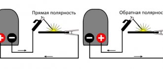
AC brushed motor
Consider a brushed AC motor. Universal commutator motors can be powered from both AC and DC sources. They are often used in power tools, sewing and washing machines, meat grinders - where reverse is needed, adjustment of the rotor speed or its rotation at a frequency of more than 3000 rpm.
The stator and rotor windings of a commutator motor are connected in series. Current is supplied to the rotor windings through brushes in contact with the commutator plates, to which the ends of the rotor windings are connected.
Reversing a single-phase motor with a commutator is carried out by changing the polarity of the stator or rotor windings being connected to the network, and the rotation speed can be adjusted by changing the amount of current in the windings.
The main disadvantages of such an engine:
- high price;
- the complexity of the device, the practical impossibility of repairing it independently;
- significant noise level, difficult to control, creating radio interference.
It remains to add that when using devices containing a single-phase electric motor, close attention should be paid to the choice of its type, connection diagram, and how to correctly calculate the elements.
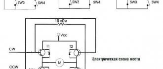
Connecting a commutator motor with reverse
When reversing such an engine, you need to remember that:
- Not all brushed motors can be reversed. If there is an arrow indicating the direction of rotation, the motor cannot be reversed.
- Motors with high rotational speed can only operate in one direction, for example, angle grinders.
- If the speed is low, then you can change the direction (drills, washing machines, etc.).
Above is a diagram of a commutator motor with reverse, powered by various types of current. To change the direction, it will be enough to change the polarity on the rotor or stator winding, just like in motors with a constant current.
By simply changing the polarity of the supply voltage, the rotor rotation will not change. This must be taken into account when connecting a commutator motor with reverse.
Keep in mind that in power units with high power, the armature winding is switched. When the windings switch, the inducing voltage itself begins to increase, reaching values that lead to motor breakdown.
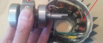
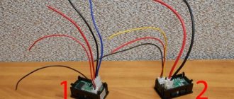
Home craftsmen often use different types of motors to create their crafts. This can be a brush motor installed on automatic washing machines, which are quite convenient because they are connected directly to the two hundred and twenty volt home network.
They do not require additional capacitors, and the rotation speed can be changed with a conventional power regulator. 6-7 wires go to the terminal block.
It depends on the type of motor:
- Two conductors are fed to the commutator brushes.
- Two wires from the speed sensor.
- The exciting windings have two or three conductors. The third conductor regulates the speed.
Reversing the washing machine motor is done by rearranging the leads of the exciting winding. The third pin, if present, is not used.