Very often, novice radio amateurs ask the same question: - How to connect a universal Chinese voltmeter-ampmeter to a homemade charger or regulated power supply? Lately I have been literally inundated with questions about how to connect, where to connect. Therefore, I decided to write a specially separate article in which I will tell you in detail how and how to connect a Chinese voltmeter-ampmeter to a charger or a homemade regulated power supply.
Today, there are two popular Chinese, universal models of voltmeters and ammeters with a built-in shunt, which all beginners and professional radio amateurs, without exception, love to buy in China on AliExpress.
Let's take a closer look at the two models of the most popular voltmeters and ammeters made in China.
Both devices have five wires for connecting to the power supply. The first one on the left has three thick wires (black, blue, red) and two thin ones (black, red). Thin wires are designed to power the device: red plus, black minus. Thick wires: Black minus ammeter, blue ammeter output, red voltmeter input.
The second device also has five wires, three thin (black, red, yellow) and two thick wires (black, red). Thin wires are designed to power the device: red plus, black minus, yellow voltmeter input. Thick wires: black minus ammeter, red ammeter output.
Every Chinese universal measuring device (UMU) has a built-in measuring shunt for an ammeter, and this is a big plus, because there is no need to “farm” anything, it is done according to the “set it and forget it” principle. In some KUIPs, the shunt is curved like the letter “M” and shiny; I got copies with a copper “P” shaped shunt. As I understand it, the shape and color of the shunt does not affect the quality of measurements in any way.
The devices on the board have tuning SMD resistors with the help of which it is possible to correct the readings of the voltmeter and ammeter.
This figure shows a diagram of connecting a voltmeter-ampmeter of the first model to a charger from a computer power supply.
The device is powered from a separate power source; in this case, it is a five-volt charger from the phone, which can be easily placed in the power supply housing.
The fact is that if you connect a voltmeter-ampmeter to the regulated output of the power supply, then when the voltage drops below 4.5V, the device will simply stop working.
The fan speed will also decrease, but at low voltage the power supply heatsinks will be a little warm and nothing bad will happen.
When the output voltage is more than 12V, the L7812CV voltage stabilizer comes into operation and thereby maintains a constant voltage on the fan of no more than 12V.
This figure shows a diagram of connecting a voltmeter and ammeter of the second model to a charger from a computer power supply.
With a charger from a computer power supply, everything is clear. Let's look at the diagram for connecting a Chinese voltmeter-ampmeter of the first model to an adjustable power supply.
The top part of the diagram shows a short-circuit protected regulated power supply consisting of a diode bridge, a capacitor, an LM317 voltage regulator, an MJE13009 transistor, a variable resistor and three fixed resistors.
Thickness gauge readings for ixtrail
At the bottom of the circuit, the fan and the Chinese voltmeter-ampmeter are connected through the L7812CV voltage stabilizer to the output of the diode bridge in parallel with capacitor C1. The stabilized voltage on the fan and control unit is no more than 12V.
This figure shows a diagram of connecting a Chinese voltmeter-ampmeter of the second model to an adjustable power supply.
Many radio amateurs prefer to install analog Chinese measuring instruments (MCIs), which have not lost their popularity over the years, in chargers and regulated power supplies. Therefore, I propose to consider the connection diagram of a classic pointer voltmeter and ammeter.
This figure shows a wiring diagram for a voltmeter and an ammeter with a built-in current measuring shunt.
The voltmeter is connected in parallel to the power source, observing polarity. The device should have plus and minus marks. The ammeter is usually connected to the negative wire after the voltmeter. You can also connect the positive wire into the gap; the method of connecting the device does not affect the accuracy of measurements. The main condition is maintaining polarity.
Sometimes there are ammeters without a built-in current-measuring shunt. Then the shunt has to be purchased separately. To avoid additional costs, before purchasing an ammeter, always check with the seller about the presence of a shunt inside the device. Sometimes the cost of a separate shunt is higher than the cost of a device with a built-in shunt.
This figure shows a diagram of connecting a voltmeter and ammeter with a separate current-measuring shunt to the power supply.
Content
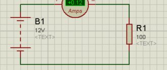
Current strength $I$ is an important characteristic in electricity. It directly depends on the magnitude of the electric charge $q$ transferred by the particles and on the time $t$ during which this charge passes through the cross section of the conductor.
It is not always possible to look inside a conductor, measure the transferred charge and calculate the current strength using the formula $I = \frac{q}{t}$. But it is possible to measure the current using a special device.
This device is called an ammeter . In this lesson you will learn how to use it to measure current and how to properly connect it to an electrical circuit.
Adjustment of the measuring system
For the manufacture of factory products, materials are used that do not change their characteristics over a wide temperature range. Therefore, the best option is to select a ready-made shunt and adjust it for your purposes by reducing the cross-section and length of its conductor to match the calculated value. But to make a shunt for an ammeter, you can also use improvised materials: copper or steel wire, even paper clips will do.
Now you need a power supply with a voltage regulator to deliver the required current. For the load, you can use a resistor of appropriate power or incandescent lamps.
First, we achieve compliance with the total deflection of the instrument needle at the maximum value of the measured value. At this stage, we select the resistance of our homemade product to the maximum possible coincidence with the final mark on the scale.
Then we check whether the intermediate risks coincide with their corresponding values. If not, we disassemble the ammeter and redraw the scale.
And when everything worked out, we install the finished device in its place.
Source: electriktop.ru
Ammeter
An ammeter is a device for measuring current in an electrical circuit.
In terms of operation and appearance, an ammeter is very similar to a galvanometer. Its design has been modified so that it is possible not only to detect the presence of current in the circuit, but also to measure its strength .
In what units is the ammeter scale calibrated? Since it measures current, its scale will be graduated in amperes .
Different types of ammeters may differ from each other depending on the application. Figure 1, a shows a demonstration ammeter . Such devices are most often used in schools when demonstrating experiments.
Figure 1, b shows an ammeter, which is often used for laboratory work.
Figure 1. Demonstration and laboratory ammeters
As you can see, these two ammeters are designed to measure a specific range of current values. The scale of the first ammeter will show a maximum value of $3 \space A$, and the second - $2 \space A$. It is not recommended to exceed these values, as the devices may fail.
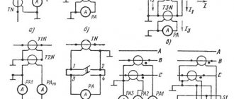
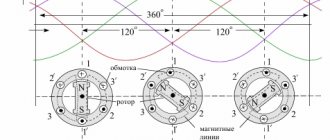
Purpose and design features of instrument transformers
Step-down blocks are used in measuring and computing systems. They have one main and several additional coils. Ammeters are connected to a secondary circuit, where the primary and secondary currents are directly proportional to each other. The current strength depends on the number of turns and the internal resistance of the wire. This voltage is safe for operating personnel and allows work to be carried out without risk to life.
The windings of the measuring units are made on a ferrite rod. When voltage is applied to the main coil, a magnetic field is generated that varies in space. Such oscillations generate electromotive force in the secondary windings.
Rules for connecting an ammeter to an electrical circuit
- The ammeter must be connected in series with the device/conductor in which the current is to be measured (Figure 3)
Figure 3. Series connection of an ammeter to an electrical circuit
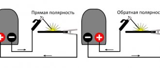
- The ammeter has two terminals for connecting conductors. The terminal with the “+” sign must be connected to the wire coming from the positive pole of the current source. And, accordingly, the terminal with the “-” sign must be connected to the wire coming from the negative pole of the current source (Figure 4).
Figure 4. Correct connection of the ammeter, taking into account the positive and negative poles of the current source
- You cannot connect an ammeter to a circuit in which there is no current consumer (receiver) (Figure 5). This may cause the device to malfunction.
Figure 5. Impossibility of connecting an ammeter to a circuit without an electricity consumer
Electrical voltage measurement process
When working with electrical appliances, special care must be taken. Any sudden movement may cause a short circuit. What to consider during the workflow? Safety precautions include several simple rules:
Correct fixation of the probes. When testing the voltage, it is necessary to hold the measuring parts safely. You should not touch them to each other. It is not recommended to touch the probes when connecting the voltmeter to an electronic circuit. This may cause a short circuit.
The black probe is installed to one of the parts of the DC conductor. Voltage drops can be correctly measured in a parallel position of the meters.
The red probe makes a tangential movement. If the device has a maximum voltage, its exact values will appear on the device.
The maximum measuring range is set on the device. If there are any problems in the electrical circuit, then note the active movement of the arrow towards the high mark.
When the research has come to an end, they move on to deciphering it.
Measuring current with an ammeter
The first rule for connecting an ammeter to a circuit is that it is connected in series. Is there a difference where exactly with this connection we place the ammeter?
Let's assemble an electrical circuit. It will consist of a current source, a key, a light bulb and an ammeter (Figure 6).
Figure 6. Series connection of an ammeter (option No. 1)
After closing the circuit, we record the current strength shown by the ammeter.
Now let's move the ammeter in the circuit so that it stands after the lamp, and not before it (Figure 7).
The ammeter will show us the same current value as in the previous case.
Figure 7. Series connection of an ammeter (option No. 2)
Now let’s connect two ammeters to the circuit at once (Figure 8). And what will we see? They will show the same current values , exactly the same as in previous experiments.
Figure 8. Series connection of two ammeters in an electrical circuit
What does this tell us?
In a circuit with a series connection of conductors (so that the end of one conductor is connected to the beginning of another), the current strength in all parts of the circuit is the same.
Why is it the same? The fact is that the charge that passes through any cross section of the conductors of the circuit in $t = 1 \space s$ is the same. After all, the current flows evenly through all the wires of the circuit, without accumulating anywhere. Its flow can be compared to the flow of water through pipes.
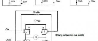
How do ammeter and voltmeter work?
The designs discussed above are suitable for creating one or another device. The difference is not only in the connection diagram. The markings and resistance of the induction coil differ. The built-in resistor limits the current/power in the ammeter/voltmeter, respectively.
In the first version, it performs the functions of a shunt. A parallel connection with minimal electrical resistance ensures that most of the current flows through this circuit. This protects the inductive element from damage.
In the second, a resistance is selected that is many times greater than the corresponding value of the coil. Another feature is the choice of resistor material with minimal changes in operating parameters with increasing (decreasing) temperature.
Safe and dangerous current limits
Working with electrical circuits can be dangerous if safety instructions are not followed. If we are talking about direct current (the magnitude of the current and its direction do not change over time), then the effects of such current on the human body are shown in Table 1.
| $I$, $ma$ | Impact on the human body |
| 0 — 3 | Not felt |
| 4 — 7 | Itching. Warming sensation |
| 8 — 10 | Increased heating |
| 11 — 25 | Even more intense heating, slight contractions of the arm muscles |
| 26 — 80 | Strong feeling of heating. Contractions of the arm muscles. Convulsions, difficulty breathing. |
| 81 — 100 | Respiratory paralysis |
Table 1. Effect of direct current on the human body
Why control the charge current in the battery?
The use of a measuring device can be considered using the example of a typical technological operation. A serviced car battery is infected using a special technique. Set and maintain the current value at 10% of the capacity specified in the passport data. This prevents excessive release of explosive gases. The duration of the procedure (24 hours or more) implies the need to supplement the device with automatic shutdown means.
Using the information provided, you can independently select a suitable device, perform measurements, and assemble a shunt circuit. At the preliminary preparation stage, the expected operating range and operating conditions should be clarified. When purchasing, it is recommended to study the manufacturer's official instructions.
Exercises
Exercise No. 1
When the ammeter was connected to the circuit as shown in Figure 9, a, the current strength was $0.5 \space A$.
What will be the readings of the ammeter when it is connected to the same circuit as shown in Figure 9, b? Figure 9. Options for connecting an ammeter to an electrical circuit
The current strength will be exactly the same. The ammeter will show a value of $0.5 \space A$. This is explained by the fact that in this electrical circuit all elements are connected in series. In this case, the current strength in all sections of the circuit is the same.
Exercise No. 2
How can you check the accuracy of an ammeter reading by using another ammeter that has been verified to be accurate?
It is possible to assemble a circuit as in Figure 6 using an accurate ammeter. Record the current value that it will show. Then replace it with another one, the one whose accuracy we want to check. Next, all that remains is to simply compare the readings of this ammeter with those obtained earlier.
You can do this in another way. To do this, you need to assemble a circuit, as in Figure 8, with serial connections of all elements. We already know that in such a circuit two working ammeters should show the same values . The main thing during such a check is to note for yourself which ammeter shows accurate measurement results, so as not to get confused.
Exercise #3
Consider the ammeters given in Figure 1. Determine the scale division value of each ammeter.
What is the highest current they can measure? Redraw the ammeter scale (see Figure 1, a) in your notebook and show what the position of the arrow will be at a current strength of $0.3 \space A$ and $1.5 \space A$. The scale of the demonstration ammeter from Figure 1, a, will have a division value equal to $0.2 \space A$.
The scale of the laboratory ammeter from Figure 1, b will have a division value equal to $0.05 \space A$.
In Figure 10, a we depicted the scale of a demonstration ammeter, which shows the value $I = 0.3 \space A$, and in Figure 10, b - $I = 1.5 \space A$.
Figure 10. Current values on the ammeter scale