Issues covered in the PUE
Regulation of the operating procedure for various types of protective systems can be presented in the form of a certain set of requirements relating to the arrangement of individual structures.
According to them, the functional readiness of grounding loops, which include a whole set of structural elements, must be confirmed by the following technical data:
- Description of the design and composition of protective devices used in existing electrical installations;
- Formulas for calculating their sizes, as well as the resistance standards of grounding devices (GD);
- Tables with correction factors that allow you to introduce corrections for the quality and condition of the soil at the location of the contour (taking into account the material of individual elements);
- The procedure for organizing and conducting control tests available for grounding systems.
On a note. The presence of documented data on the performance characteristics and reliability of the functioning of the grounding loop of a private house, for example, will eliminate the possibility of electric shock to animals and residents.
When installing it, you are required to act in strict accordance with the PUE, as well as comply with all requirements regarding the operation of this protective device.
Why do grounding in a private house?
The operation of electrical appliances in a residential building is accompanied by the risk of short circuits or damage to the insulating coating of the wires. Such areas are dangerous to human life. If he touches faulty electrical equipment, he will receive an electric shock because... the body is a good conductor.
Therefore, for the safety of residents, all country cottages must be equipped with grounding devices, which also prevent premature failure of household electrical appliances.
Circuit design
Components
Ground loop
The previously mentioned grounding resistance (Rз) of the circuit is the main parameter controlled at all stages of its operation and determines the effectiveness of its use. This value must be so small as to provide a free path for the emergency current tending to flow into the ground.
Note! The most important factor that has a decisive influence on the value of grounding resistance is the quality and condition of the soil at the site of the installation.
Based on this, the charger in question or the ground loop of the charge circuit (which in our case is the same thing) must have a design that meets the following requirements:
- It must include a set of metal rods or pins with a length of at least 2 meters and a diameter of 10 to 25 millimeters;
- They are connected to each other (necessarily for welding) by plates of the same metal into a structure of a certain shape, forming a so-called “grounding conductor”;
- In addition, the device includes a supply copper busbar (also called electrical) with a cross-section determined by the type of equipment being protected and the magnitude of the drain current (see the table in the figure below).
Tire Section Table
Additional Information. Conventionally, this design includes connecting copper wires in the form of a bundle or braid.
These component devices are necessary to connect the elements of the protected equipment with the descent (copper busbar).
Differences in device location
According to the provisions of the PUE, the protective circuit can have both external and internal design, and each of them is subject to special requirements. The latter establishes not only the permissible resistance of the ground loop, but also stipulates the conditions for measuring this parameter in each particular case (outside and inside the object).
When dividing grounding systems according to their location, it should be remembered that only for external structures the question of how the grounding resistance is normalized is correct, since it is usually absent indoors. Internal structures are characterized by wiring of electrical busbars along the entire perimeter of the premises, to which grounded parts of equipment and devices are connected through flexible copper conductors.
For structural elements grounded outside the facility, the concept of re-grounding resistance is introduced, which appeared as a result of the special organization of protection at the substation. The fact is that when forming a neutral protective conductor or a working conductor combined with it at the supply station, the neutral point of the equipment (step-down transformer, in particular) is already grounded once.
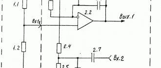
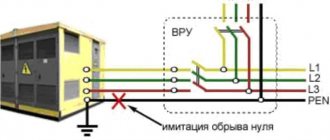
Therefore, when another local grounding is made at the opposite end of the same wire (usually a PEN or PE bus connected directly to the consumer panel), it can rightfully be called repeated. The organization of this type of protection is shown in the figure below.
Re-grounding
Important! The presence of local or repeated grounding allows you to insure yourself in case of damage to the protective neutral wire PEN (PE - in the TN-CS power supply system).
Such a malfunction is usually found in technical literature under the name “zero burnout.”
Technical requirements for the organization of grounding of electrical installations
Ultrasound is used to protect people and equipment from the destructive effects of electric current. Safety is ensured by connecting the protected enclosures of electrical installations to the ground. Work on organizing grounding networks is regulated by the provisions of GOST 12.1.030-81, according to which protective grounding of an electrical installation should be carried out under the following parameters:
- at rated voltage values of 380 V or more alternating current and more than 440 V or more direct current - at any values;
- at rated voltage values of 42-380 V AC 110-440 V. For work associated with increased danger.
A properly organized grounding system for electrical installations can neutralize excess potential of any power and protect people, equipment and buildings from the effects of electric current, whether surges caused by turning on or off power equipment or lightning.
The operating principle is based on the difference in resistance of the human body and ultrasound. Excess potential is diverted in the direction of a lower indicator, i.e. towards the protective circuit.
Selection of natural ground electrodes
According to the rules for the construction of electrical installations, their housings must be connected to artificial or natural grounding conductors. The following metal objects are used as natural ones:
- frames of underground metal structures having direct contact with the ground;
- protective covers for cables laid underground;
- metal pipes, with the exception of gas and oil pipelines;
- railway rails.
Contact of the object with the natural ground electrode must be made in at least two places. The advantages of this method are simplicity, efficiency and cost reduction in organizing an electrical safety system.
The following objects cannot be selected as natural grounding conductors:
- pipelines of flammable and explosive gases and liquids;
- pipes coated with anti-corrosion insulation;
- sewer pipelines;
- central heating pipes.
Current flow resistance
Grounding works according to the following principle: the current flowing into the ground through the fault point first passes to the body of the electrical installation and from it through the ultrasound into the ground. Obviously, when organizing grounding networks up to 1000 Volts, it is important to create a chain that ensures excess charge flows into the ground.
Grounding resistance values for networks for various purposes:
| Purpose of the network | Maximum resistance value, Ohm |
| Private houses 220, 380 Volt | 30 |
| Industrial equipment | 4 |
| Current source at voltages of 660, 380 and 220 Volts | 2, 4, 8 |
| Private house when connecting a gas pipeline | 10 |
| Communication line protection devices | 2 (less often 4) |
| Telecommunications equipment | 2 or 4 |
To obtain the resistance indicators established by the standards, standard procedures should be followed:
- Increase the area of contact between the parts of the grounding device and the ground.
- Ensure high-quality contact between the device elements and the connecting busbars.
- Strengthen soil conductivity by moistening or increasing its salinity.
To monitor compliance of resistance with prescribed standards, its level should be checked at least once every six years.
Ultrasound operation in case of violation of protective insulation of electrical equipment
Violation of the integrity of the protective insulation often leads to a phase short circuit to the housing. Further developments depend on the quality of the electrical safety system. The following options are possible:
- There is no grounding, the residual current device is not installed. The most unfavorable situation. When you touch the body, a strong blow is felt.
- The housing is connected to the grounding system, there is no RCD. If the leakage current is high, the machine will operate and turn off the supply line or circuit. This option can lead to the accumulation of excess potential on the case if the resistance of the junctions and the fuse rating are high. This situation is dangerous for people.
- There is no grounding, the residual current device is installed. The leakage current will trigger the RCD and the person will only have time to feel a weak electric shock.
- The housing is connected to grounding, an RCD is installed - the most reliable option, ensuring the protection of people and equipment due to the fact that the protective devices complement and partially duplicate each other. When a phase is short-circuited to the housing, the excess potential drains through the grounding system. At the same time, the residual current device reacts to the leak and turns off the current supply, eliminating the possibility of electric shock to people. If the leakage current significantly exceeds the capabilities of the RCD, the machine may trip and duplicate its function.
Influence of soil on resistance Rз
Grounding calculation
It has been practically proven that the resistance of the grounding device is largely determined by the condition of the soil at the location of the ground electrode. In turn, the characteristics of the soil in the area of protective work depend on the following factors:
- Soil moisture at the work site;
Additional Information. When assessing moisture content, you should know that shale and clay retain water well, while sandy soils, on the contrary, do not.
- The presence of rocky components in the soil, in which it is simply impossible to arrange grounding (in this case, you have to choose another place);
- Possibility of artificial soil moisture during particularly dry summer periods;
- Chemical composition of the soil (presence of salt components in it).
Depending on the composition of the soil, it can be classified as one or another type (see photo below).
Different types of soil
Based on the peculiarities of the formation of the resistance of the ground electrode, which suggests its decrease when moistened and the salt concentration increases, in case of emergency, portions of the wet chemical NaCl are artificially introduced into the soil.
Good soils from the point of view of grounding arrangement are loamy soils with a high content of peat components and salts.
Which is better - homemade contours or a purchased kit?
To equip the grounding of a country house, you can buy a ready-made device kit. This will allow you to quickly install the structure, often without even the use of welding equipment. To connect individual elements, manufacturers make special fasteners.
Factory designs are considered more reliable because... All parts are made of stainless metal and are additionally treated with protective compounds. But they are expensive - from 7,000 to 10,000 rubles.
A grounding system assembled with your own hands from materials available at home allows the owners of a private cottage to save a lot of money. And if you correctly calculate the circuit and carry out the installation work efficiently, the homemade design will last no less than the factory one.
Design and types of circuits
The task and features of grounding transformers.
The standard ground loop is made not only in the form of a triangle, which is optimal for most conditions; it can be in the shape of a line, a rectangle, an angle, or even an arc (oval). When considering each of these structures from the point of view of their resistance, the following should be noted:
- The basis of the design is pins or rods driven into the ground;
- They are connected to each other by metal strips cut to length (the so-called “metal bond”);
- A copper busbar is welded to one of the pins or to a strip of metal, laid in a separate groove, as shown in the figure below.
Laying the busbar to the short circuit structure
The choice of a triangle as the main type of ground electrode is explained by the fact that in this case it is possible to obtain the maximum dispersion zone with a small occupied area. The material costs for such a structure are minimal, and the resistance to spreading in the ground, if properly constructed, complies with the standards.
The distance between the pins of a triangular contour is usually chosen equal to the length, and the maximum distance from one to the other can be twice as large. So, if the pins are buried 250 centimeters into the ground, it can reach 5 meters. Only if these conditions are met is it possible to obtain optimal characteristics of a structure buried in the ground.
The linear contour is a chain of pins driven into the ground at a certain pitch of approximately 5-10 meters (see the figure below).
Linear distributed circuit
In some cases, depending on terrain conditions, the structure is constructed in the form of a semicircle; in this case, the pins are located at the same distance from one another. In such a distributed device, the resistance should be minimal precisely at the points of contact of the rods with the ground. To achieve the required R3 value, as many pins as possible are hammered in.
All other types of structures are modifications of the ground electrodes described above, and the requirements for drainage resistance are derived from those already considered.
Types of material (profiles)
According to the requirements of the PUE, which contain instructions on what the resistance of current flow in the ground should be, in most cases this indicator is set at a level of no more than 4 ohms. To obtain this value, you usually have to make a lot of effort to adhere to the same technology requirements.
First of all, this concerns the materials used in assembling the grounding loop, selected based on the following conditions:
- When choosing pins, preference should be given to ferrous metal blanks;
- The most commonly used rod is a standard size of 16-20 mm or a corner with parameters 50x50x5 mm and a metal thickness of about 5 mm;
- It is not allowed to use reinforcement as circuit elements, since it has a hardened surface that affects the normal flow of current;
- For these purposes, it is pure rod that is suitable, and not its reinforcement substitute.
Note! For areas with dry summers, thick-walled metal pipe blanks are best suited, the lower end of which is flattened into a cone, and then several holes are drilled in this part of the pipe.
According to the provisions of the PUE, before placing them in the ground, holes of the required length are first drilled, since driving them in manually is quite problematic. In the case of a particularly dry summer and a sharp deterioration in the parameters of the ground electrode, a concentrated saline solution is poured into the hollow parts of the pipes, which makes it possible to obtain the resistance that should be in accordance with the requirements of the PUE. The length of pipe blanks is selected within 2.5-3 meters, which is quite enough for most Russian regions.
This type of profile blanks has special requirements regarding the order of their placement in the soil and consists of the following:
- Firstly, the pipe elements of the protective circuit must be placed at a depth exceeding the soil freezing level by at least 80-100 cm;
- Secondly, in particularly dry areas, approximately a third of the length of the ground electrode should reach wet soil layers;
- Thirdly, when fulfilling the second condition, one should focus on the peculiarities of the location of the so-called “groundwater” in a given region. If they are located at a significant depth, according to the rule formulated in the provisions of the PUE, it will be necessary to prepare longer pipe sections.
The type and profile of the pin blanks used in the construction of the grounding switch can be found in the figure below.
Acceptable pin profiles
In practice, in most regions of Russia, a steel corner and a strip of the same metal are usually used. In order to obtain more accurate parameters of the grounding elements used, geological survey data will be required. If this information is available, it will be possible to involve specialists in calculating the parameters of the ground electrode.
What is metal bonding made of?
The elements connecting the pins (metal bond) are usually made of the following electrical materials:
- A typical copper busbar with a cross-section of less than 10 mm2;
- Aluminum strip with a cross section of about 16 mm2;
- Steel strip 100 mm2 (standard size – 25x5 mm).
Classic metal ties are usually made in the form of steel strips cut to size and welded to the corners or heads of the rod.
Important! The quality of the welding joint determines whether a given grounding device or circuit can pass verification tests for compliance of the contact resistance with the standardized value (4 Ohms).
When using more expensive aluminum (copper) strips, a bolt of a suitable size is attached to them for welding, on which the supply busbars are subsequently fixed. The main thing you need to pay attention to when arranging any connections is the reliability of the resulting contact.
To do this, before preparing the bolted joint, it is necessary to thoroughly clean both parts to be connected until the shine of clean metal appears. Additionally, it is advisable to sand these places, and after tightening the bolt, tighten it well, which will ensure more reliable contact.
Chapter 1.7 grounding and electrical safety precautions
MINISTRY OF FUEL AND ENERGY OF UKRAINE
ORDER
August 28, 2006 №
305 Kyiv
On approval and entry into force of the new edition of Chapter 1.7 of the Electrical Installation Rules
In order to put into effect a new edition of Chapter 1.7 “Grounding and protective measures for electrical safety” of the Electrical Installation Rules (hereinafter referred to as the PUE)
I ORDER:
1. Approve the new edition of Chapter 1.7 of the PUE “Grounding and protective measures for electrical safety”, which comes into force on January 1, 2007 (attached).
2. The self-supporting division “Scientific and Engineering Energy Service (Belousov V.I.) should add Chapter 1.7 of the PUE to the register and computer data bank of current regulatory documents of the Ministry of Fuel and Energy.
3. The association of energy enterprises “Industry Reserve Investment Fund for Energy Development” (V.T. Kodaneva) ensures the publication and distribution of Chapter 1.7 of the PUE based on orders from interested organizations and actual payment.
4. Department for Electric Power Issues (Mezhenny S.Ya.), Association of Energy Enterprises "Industry Reserve Investment Fund for Energy Development" (Kodaneva V.T.) and the Institute "Ukrselenergoproekt" (Lyakh V.V.) within a month from the date signing an order to develop a program of measures for the implementation of the new chapter 1.7 of the PUE.
5. The Ukrselenergoproekt Institute (V.V. Lyakh) to provide scientific and technical support for the process of implementing the new edition of Chapter 1.7 of the PUE.
6. From the moment the new edition of Chapter 1.7 of the PUE comes into force, Chapter 1.7 of the PUE of the sixth edition “Grounding and protective measures for electrical safety”, approved on April 30, 1980 by the Main Technical Directorate and State Energy Supervision of the USSR Ministry of Energy, shall be declared invalid.
7. Control over the implementation of this order shall be entrusted to the Deputy Minister of Fuel and Energy of Ukraine O. M. Sheberstov.
Minister Yu. Boyko
APPROVED Order of the Ministry of Fuel and Energy of Ukraine dated August 28, 2006 No. 305
Application area
1.7.1. This chapter of the Rules applies to electrical installations of alternating and direct current intended for the production, conversion, transformation, transmission and distribution of electricity that are designed, built or reconstructed, and contains general requirements for their electrical safety both in normal operation of electrical installations and in the event of damage isolation. The requirements of this chapter may also be applied to existing electrical installations in order to improve their electrical safety.
Electrical safety measures in electrical installations with voltage up to 1 kV of buildings and structures (residential, administrative, public, workshop, etc.) are regulated by DBN V.2.5-27-2006 and other regulatory documents in force in Ukraine.
1.7.2. With regard to electrical safety measures, electrical installations are divided into:
— electrical installations with voltage up to 1 kV in electrical networks with a solidly grounded neutral;
— electrical installations with voltage up to I kV in electrical networks with an insulated neutral;
— electrical installations with voltages above 1 kV in electrical networks with an isolated, compensated and/or neutral grounded through a resistor;
— electrical installations with voltages above 1 kV in electrical networks with a solidly grounded or effectively grounded neutral.
Note.
The requirements of this chapter for electrical installations with voltage up to 1 kV also apply to electrical installations with voltage up to 1.5 kV of direct and rectified current, the alternating component of which does not exceed 10% of the effective value.
Terms and definitions
1.7.3. electrical safety
— no threat from the electrical installation to life, health and property of people, animals, plants and the environment, exceeding the permissible risk.
1.7.4. Electrical network with effectively grounded neutral point
- a three-phase electrical network with a voltage above 1 kV, in which the ground fault coefficient does not exceed
1.4.
Ground fault coefficient in a three-phase network
- the ratio of the potential difference between the undamaged phase and the earth at the point of an earth fault of another or two other phases to the potential difference between the phase and the earth at this point before the fault.
1.7.5. Solidly grounded neutral
- neutral of a generator or transformer, connected to a grounding device directly or through low resistance (for example, through current transformers). The output of a single-phase current source or the pole of a direct current source in two-wire networks, as well as the middle point of the source in three-wire AC and DC networks can also be solidly grounded.
Midpoint
- a common point between two symmetrical circuit elements, the opposite ends of which are connected to different linear conductors of the same circuit.
Linear (phase) conductor
- a conductor that is energized during normal operation of an electrical installation and is used for the transmission and distribution of electrical energy, but is not a midpoint conductor or a neutral conductor.
1.7.6. Isolated Neutral
- neutral of a generator or transformer, not connected to a grounding device or connected to it through a high resistance of signaling, measuring and other similar devices, the presence of which has practically no effect on the ground fault current.
Compensated neutral
- neutral of a generator or transformer connected to a grounding device through arc suppression reactors to compensate for capacitive current in the network during single-phase ground faults.
Neutral grounded through a resistor
— the neutral of a generator or transformer in a network with an isolated or compensated neutral, connected to a grounding device through a resistor, for example, to protect the network from overvoltages and/or to perform selective protection in the event of a ground fault, which leads to an increase in the fault current.
1.7.7. Conductive part
- any part that has the property of conducting electric current.
1.7.8. Conductor
- a conductive part designed to conduct an electric current of a certain value.
1.7.9. Live part
- a conductor or conductive part which, in the course of its normal operation, is live, including a neutral conductor, but not a PEN conductor.
1.7.10. Exposed conductive part
- a conductive part of an electrical installation that is accessible to touch, which during operation is not under operating voltage, but may become energized if the insulation of conductive parts is damaged (for example, the housing of electrical equipment, etc.).
Source: https://ohranatruda.in.ua/pages/4996/
Self-production
After preparing all the necessary materials and choosing a suitable place for arranging the grounding, you can proceed to the direct operations of assembling the grounding loop. At the preparatory stage, pipe or other profile sections are cut, the size of which is chosen to be 20-30 cm larger than the calculated one (this is necessary to compensate for the bending of the top of the workpiece when it is driven into the ground).
Additional Information. To make it easier to hammer in such sections, it is recommended to sharpen their lower edge using a grinder with a trimming disc.
Simultaneously with the preparation of point pin grounding conductors, the stage of excavation begins, consisting of the preparation of grooves with beveled edges (to better retain the soil from shedding).
The order of operations performed during excavation work is as follows:
- First, the site for the future ground loop is prepared (cleared) and its markings are made;
- Then, using the already applied markings, grooves are dug with a depth of 70-80 cm and a width of about 50 cm (the depth is chosen to minimize corrosion of metal bonds);
- After this, the pins, cut to length, are driven in at the designated points so that about 20 cm protrude above the surface (see photo below);
Arrangement of a grounding loop
- Upon completion of the installation of all vertical elements, their upper parts are cut off, and the contact pads are thoroughly cleaned, after which metal connections are welded to them;
- After all welding seams have cooled, they are cleaned with a grinder and a grinding disc, and then painted with a special tar-based protective paint;
Note! Only the areas of welded joints that are most susceptible to corrosion are painted.
- Next, from the short-circuit point closest to the residential building, a ditch is dug to the same depth that was dug under the metal connections (its width may be slightly smaller, since the connecting strip is made solid and does not require welding);
- Then a strip of metal with a standard size of at least 25x4 mm is laid in the prepared trench, which is subsequently welded to a pin or jumper (metal bond);
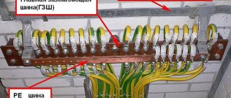
- At the final stage of work, near the wall of the house, the already laid metal strip is raised to a height of about 200 mm, where a busbar (wire) is connected to it by bolting or welding, going to the main distribution board (photo below).
Input of grounding into the house
To connect the finished grounding to the existing power supply circuit, you will need to familiarize yourself with the existing grounding schemes.
Entering the house
The circuit is connected to the grounding bus of the distribution system using a steel strip with a standard size of 24x4 mm or copper and flexible wire with a cross-section of 10 mm². In some cases, specifically specified in the PUE, it is allowed to use aluminum wire with a cross-section of 16 mm² for this purpose (see figure below).
Scheme of grounding installation in the panel
If there is a choice between the options proposed above, preference is given to copper wire, which has the most suitable characteristics for the task.
In the final part of the review, we draw the attention of users to the fact that it is not very easy to make a grounding loop with your own hands, since when carrying out this work, strict compliance with the requirements of the PUE is necessary. For those who are not completely confident in their abilities, there is always a “backup” way out - to invite representatives of an organization specializing in the manufacture of groundings.
What is required for grounding
To independently arrange a grounding system for a country residential building, you will need the following tools and materials:
- bayonet shovel;
- sledgehammer;
- set of wrenches;
- welding machine;
- perforator;
- Bulgarian;
- corner 50x50 mm made of stainless steel (2 m long);
- copper wire with a cross section of 6 mm²;
- a stainless steel strip 4x40 mm (its length is equal to the distance from the porch of a residential building to the location of the ground loop);
- 3 metal strips (each length is 120 cm, minimum thickness is 4 mm, width is 4 cm);
- bolt M10 or M8.
It is not recommended to skimp on the thickness of the electrodes - the reliability and service life of the grounding structure depends on this.
Video
Coffee capsule Nescafe Dolce Gusto Cappuccino, 3 packs of 16 capsules
1305 ₽ More details
Coffee capsules Nescafe Dolce Gusto Cappuccino, 8 servings (16 capsules)
435 ₽ More details
Batteries