Is grounding necessary in a private house?
When using any electrical appliances in the house, there is always a risk of damaging the insulation of the wires or shorting them to the housing.
In this case, any person touching the dangerous zone leads to electric shock, which can end tragically. The current always tends to the ground, and the human body becomes a conductor connecting the damaged device to the ground. What does grounding do? Essentially, it is a system that provides the shortest path for electrical current. According to the law of physics, he selects the conductor with the lowest electrical resistance, and the circuit has this property. Almost all the current is directed to the ground electrode, and therefore only a small part of it will pass through the human body, which cannot cause harm. Thus, the ground loop ensures electrical safety. Regulatory documents (GOSTs, SNiP, PUE) indicate that any private, residential building must be equipped with it for alternating current networks with voltages above 40 V and alternating current networks with voltages above 100 V.
In addition to ensuring safety, the grounding system increases the reliability and durability of household appliances. It ensures stable operation of installations, protection against overvoltage and various network interferences, and reduces the impact of external sources of electromagnetic radiation.
Grounding should not be confused with lightning rods (lightning rods). Although the principle of their operation is similar, they perform different tasks. The job of a lightning rod is to divert lightning into the ground when it hits a house. In this case, a powerful electric charge arises, which should not enter the internal network, because can simply melt a wire or cable. That is why the lightning rod line runs from the receivers on the roof along the outer contour and should not be combined with the grounding, internal line. The lightning rod and grounding may have a common underground circuit (if it has a margin in cross-section), but the wiring must be separated.
Types of protection against electric shock
In accordance with paragraph 1.1 of GOST 12.1.030-81, protective grounding or grounding (zero-ground connection) is designed to protect people from electric shock in the event of insulation damage when they touch metal non-current-carrying parts of electrical equipment.
Grounding is an intentional or accidental electrical connection of metal parts of electrical equipment, electrical installations, or a network point to a grounding device, busbar or other protective equipment (clause 01-10-09 GOST R 57190-2016).
This could be reinforcement in the ground, building structures or special electrodes. This measure is a mandatory deliberate protection of both residential and non-residential assets.
Grounding is the deliberate connection of metal parts that are not energized in the normal state with a neutral protective conductor (solidly grounded neutral of a transformer or generator).
In accordance with paragraphs 1.1.2, 1.1.3, 1.7 of GOST 12.1.030-81, grounding must be done by electrically connecting metal parts of electrical equipment to a grounded point of the power supply using a neutral protective conductor (PE).
For neutral protective and grounding conductors, you can use: special conductors, as well as metal structures of buildings and structures.
Protective grounding and grounding of electrical equipment must be carried out without fail when using an alternating current voltage with a nominal value of 220 (1 phase) and 380V (3 phases) and higher and a direct current voltage of 440V and higher. In addition, according to clause 1.7.13 of the PUE, the power supply for electrical receivers must be supplied from a 380/220 V network with a TN-S or TN-CS grounding system.
Grounding schemes: which one is better to make?
The grounding system of a private house depends on the type of network connection to it. Most often, it is performed according to the TN-C principle. Such a network is provided by a two-core cable or two-wire overhead line at a voltage of 220 V and a four-core cable or four-wire line at 380 V. In other words, a phase (L) and a combined protective neutral wire (PEN) are supplied to the house. In full-fledged, modern networks, the PEN conductor is divided into separate wires - working or neutral (N) and protective (PE), and the supply is carried out by a three-wire or five-wire line, respectively. Taking into account the above options, the grounding scheme can be of 2 types.
TN-CS system
Provides for dividing the PEN input into parallel conductors. To do this, in the input cabinet the PEN conductor is divided into 3 buses: N (“neutral”), PE (“ground”) and a splitter bus for 4 connections. Further, conductors N and PE cannot contact each other. The PE bus is connected to the cabinet body, and the N-conductor is installed on insulators. The grounding circuit is connected to the bus splitter. A jumper with a cross-section of at least 10 sq. mm (for copper) is installed between the N-conductor and the ground electrode. In further wiring, “neutral” and “ground” do not intersect.
Reference! It is important to consider that this system is effective only when installing an RCD and a differential-type circuit breaker.
TT system
In such a circuit, it is not necessary to split the conductors, because the neutral and earth conductors are already separated in a suitable network. The cabinet simply makes the correct connection. The grounding circuit is connected to the (residential) PE wire.
The question of which grounding system is better does not have a clear answer. The CT circuit is simpler to install and does not require additional protective devices. However, the vast majority of networks operate on the TN-C principle, which forces the use of the TN-CS scheme. In addition, electrical installations with two-wire power supply are often used in everyday life. When the CT is grounded, the housing of such devices becomes energized if the insulation is damaged. In this case, TN-CS grounding turns out to be much more reliable.
Grounding connection procedure
- The phase wire leading from the apartment is connected to the bus to which the old wire was connected.
- Connecting the working neutral wire N to a bus having neutral wires.
- Connecting the grounding PE wire (neutral protective) to the panel body.
Features of grounding connection.
Connecting all grounding wires located in the panel to 1 clamp (bolt) is prohibited. For this purpose, use different bolts. The best option is to use a busbar: it is screwed to the panel, and then the PE wire is connected.
Be sure to consider the following:
- If the input is three-phase, all conductors must have the same cross-section (if they are copper, the cross-section should be no more than 16 sq. mm).
- No more than 2 conductors of the same cross-section are clamped under one terminal of the machine.
- To obtain a uniform load, it is best to use a 3-phase connection to the hob.
Each metal part in the bathroom, starting with pipes, bathtubs, heated floor screens and others, as well as the grounding conductor of the socket , if there is one in the room, is connected to the DSUP (KUP) bus, located here. The outlet is powered using a three-wire circuit.
How to connect grounding with your own hands.
The cross-section of all PE conductors with mechanical protection must be 2.5 square meters. mm, and without mechanical protection - 4 sq. mm. The cross-section of the conductor going from the DSUP bus to the PE floor panel bus should be 6 square meters. mm.
It is advisable to make the connection so that the lighting circuit and power (socket) circuits are disconnected. But it is possible to connect mixed power supply. The lines going to power units (stove, oven, automatic washing machine) are connected separately.
Some new type of apartment buildings, which have been built since 1997, are equipped with the TN-S system, which provides for the separation of neutral conductors - working and protective. This type of grounding is considered more reliable. When the house is connected, a grounding wire is laid separately, along with which the phase and neutral wires are laid from the substation to the electrical panels of the building. This creates all the necessary conditions for connecting grounding in apartments , which is carried out in the same way as described above.
How to connect grounding in a panel
It’s hard to imagine coziness and comfort in a private house or apartment without an established power supply system. Electricity consumption is constantly increasing, making it more difficult to protect people and pets from electric shock. Risks can be eliminated and the consequences of injuries can be minimized using a grounding system that connects points of the electrical network or energy consumer to a grounding structure.
Design and purpose of grounding devices
Such structures are divided into working and protective devices.
- The worker is used to organize the safe operation of industrial units. Also common in private households.
- A protective grounding system is required for electrical networks in the residential sector.
Installation of a grounding device (GD) is required in accordance with the Rules for the Construction of Electrical Installations and the Rules for the Operation of Consumer Electrical Installations.
People touching live parts exposed as a result of improper operation of electrical equipment, design defects, deterioration of insulation and other reasons is common. Poor-quality design of the charger and its installation can lead to serious consequences for people: electric shock, burns, disruption of the heart and other human organs, electric shock often leads to amputation of limbs, disability and even death.
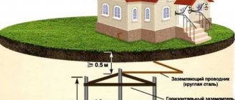
The grounding system consists of external and internal parts, which are joined in the electrical panel. An external grounding device consists of a complex of metal electrodes and conductors that drain emergency current from electrical equipment into the ground in places that are safe for people. The electrodes are called ground electrodes. Electrical conductors are grounding conductors; they are pins 1.5 m long and 1 mm in diameter.
They are manufactured industrially from copper or copper-plated steel. Their main advantage is increased current conductivity. They are driven into the ground with hammers or sledgehammers to a depth of 50 cm; contact with the ground must be as strong as possible, otherwise the structure’s ability to drain current will deteriorate.
The simple design is made from a single electrode. Used in lightning rods or to protect remote objects and equipment. In individual farms, preference is given to multi-electrode devices. They are placed in one row and are called linear memory profiles. The standard chain length is 6 meters. They are connected to each other using brass couplings; the fastening is threaded; welding is not recommended. Grounding conductors are installed through terminals. Twisting and soldering of cores are excluded.
Don't miss: Wire Size Chart. How to collect data yourself
A device such as a ground loop (closed version) is still common. It is constructed at a distance no closer than 1 meter and no further than 10 meters from the house. Placed in a trench in the form of an equilateral triangle. Side length 3 m, depth – 50 cm, width – 40 cm. Grounding conductors are driven into the corners. The same operation is performed with other vertical electrodes (no more than five units). Grounding conductors in the lower supporting part are welded to horizontal products.
They are made of copper, copper or zinc coated steel angle (5 mm flange, 40 mm strip). A standard stainless steel angle of any profile is often used. The products are not painted, as in this case the electrical properties will deteriorate due to weakened contact with the ground.
The design of the circuit is simple; you can do it yourself. But the work is simplified when using ready-made grounding devices on the market, complete with grounding wires. Financial losses will be recouped through the use of high-quality materials that are resistant to corrosion and have a long service life.
Let's analyze the situation with diagrams
From the point of view of the flow of electric current, there is no difference between grounding and grounding. The neutral wire in any case has electrical contact with physical ground.
Accordingly, when a phase is shorted to the housing, the same short circuit will occur and the circuit breaker will turn off. Of course, (subject to proper connection: the socket must have a third ground contact, just like an electrical appliance. For this reason, electricians, violating the requirements of the Electrical Installation Rules, often separate the ground bus from the zero contact of the input panel.
Let's imagine a situation where the neutral wire is broken for some reason:
- loss of contact due to corrosion (in old high-rise buildings this is a working situation);
- mechanical rupture of the cable due to repair work with violations of technology (unfortunately, also not uncommon);
- unauthorized intervention by a home-grown “electrician”;
- accident at the substation (only the zero bus may be disconnected).
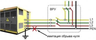
In the diagram it looks like this:
When organizing protective grounding, the electrical circuit between the physical “ground” and the grounding contact of the electrical appliance is broken. The installation becomes defenseless. In addition, a free phase without a load can create a potential equal to the input voltage at the nearest substation. Typically this is 600 volts. You can imagine the damage that will be caused to the electrical equipment that is turned on at this moment. In this case, there is no current leakage to the physical ground, and the circuit breaker will not trip.
Imagine that at this moment you simultaneously touch a phase (a breakdown on the body of an electrical installation) and a metal object that has a physical connection with the ground (a water tap or a heating radiator). You can get electrocuted at 600 volts.
Now let's see what the difference is between grounding and neutralizing (in our diagram). If the zero bus breaks, the power to all electrical installations in this circuit will simply disappear. There will be no electric shock under any circumstances: the electrical circuit between the physical ground and the grounding contact of electrical appliances is not broken. We have already preserved our health. Now let's see what happens to electrical installations. The maximum damage is a burnt-out incandescent lamp closest to the input panel. Moreover, trouble will only occur if the voltage on the phase wire increases. The current strength will increase (according to Ohm's law), the circuit breaker will work, and perhaps other electrical appliances will not be affected.
It is for this reason that the PUE strictly prescribes: protective grounding and grounding of electrical installations must be organized independently of each other, using different lines.
For reference: Wire color coding is usually used:
- The phase is brown or white.
- The working zero is blue.
- Protective grounding is a yellow-green shell.
If you have a modern home, then grounding and grounding are carried out in accordance with the Electrical Installation Rules. This can be easily checked by looking at the input cable in the panel. In addition, you can check the correct connection yourself.
Example of the need for grounding
Grounding a bathtub in an apartment
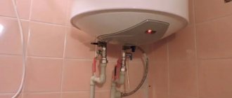
Grounding the electrical wiring is necessary to prevent shock from capacitive current resulting from voltage leakage through the branch of the LC filter, the middle of which is connected to the body of the device. Such filtering devices are used, for example, in some models of washing machines. When connecting the washing machine to an ungrounded socket, the potential difference between the surface of the device and the person next door will be equal to the input voltage divided by 2. The described case is also fraught with the possibility of false triggering of the RCD.
If you grab zero with one hand and the phase with the other, the body will become a conductor between different potentials
Another example is preventing the consequences of electromagnetic incompatibility of devices connected to the network. If the zero working cable breaks, then all devices connected to the network fail. Grounding is also important to protect electronic computing devices from electrical discharge emanating from the human body. It has low power, but sometimes it is enough for the device to fail or begin to freeze. The grounding system equalizes the potentials, thereby preventing a situation where, when the heating pipe and the computer's operating panel touch simultaneously, the latter begins to malfunction due to an electrical discharge.
Connecting the external part of the charger to the shield
To determine the exact procedure for connecting the grounding to the panel, knowledge of the method of using the neutral is required. It can be isolated and grounded. The insulated core is used in networks with increased voltage values of 3-35 kV. With a power supply of 380 V and 220 V, both options work effectively. However, the new PUE rules require the neutral to be grounded. The circuits must be built for voltages up to 1000 V.
Popular grounding systems are TN-C, TN-S, TN-CS. Two-phase TN-C is outdated, but is still used in buildings that have a long service life. Their replacement is associated with technical and financial difficulties. In this circuit, the neutral conductor is used as a protective ground wire. From a practical point of view, for residents of apartments and houses, cable and conductor products with 4 cores are beneficial: their cost is lower and installation work is simpler.
The question of how to connect grounding in a multi-storey building is of interest. The conductors are connected to the common memory bus. The bus is then routed to the electrical panel housing on the floor. The process of converting TN-C to TN-CS in the home panel is similar. The idea is to connect the neutral protective conductors to a single bus of the charger and then attach it with a jumper to the zero bus.
The main disadvantage is associated with the risk of damage to the neutral wire. Then the grounding structure will become unusable. Regulatory documents have introduced a ban on the use of TN-C in new buildings. But it will take decades to completely replace the system.
The principle of operation of TN-S is based on the fact that the zero operating and protective lines are supplied to the consumer by separate conductors from the transformer substation. In the Russian Federation and CIS countries, an intermediate version of TN-CS is common, in which the conductors are separated directly upon entry into the house. In both options, the safety functions are performed by a residual current device (RCD).
How to make grounding when there is none
Regarding the question of how to make grounding in an apartment if there is none at all, the following should be noted. In this situation, three options are possible, namely:
- Use of RCD.
- Installation of the local circuit.
- Other techniques.
Let's look at each of them in more detail.
RCD connection
If grounding in an apartment is not provided for by the design, and it is absolutely impossible to do without it, it is allowed to use special RCD devices. These devices react to the slightest current leakage from the housings of the protected equipment and instantly disconnect the damaged supply line from the general 220 V network (photo below).
RCD residual current device. Connection diagram in the apartment
Installation of an individual circuit
Residents of panel buildings often agree to arrange grounding in their apartments with their own hands, which will require a separate grounding electrode. To implement this idea, a copper core with a cross-section of at least 4 mm square is thrown from the common panel towards the basement along the installation riser. The next steps are as follows:
- A structure is being built next to the entrance, the shape and composition of which is shown in the figure below.
- To obtain it, three metal corners of a suitable cross-section are driven into the corners of a pit dug in the form of a regular triangle.
- Then they are welded together with wide metal strips.
- Upon completion of welding, a grounding copper wire lowered from the access panel is attached to one corner of the triangular structure on a bolted connection.
You can read more about this design in our article “Grounding loop, what it is and how it works”
Ground loop
In addition, you will need to completely update the apartment electrical wiring, which should have a third grounded wire.
At the final stage of the work, it remains to connect the third core of the updated electrical wiring to the grounding plate of the shield.
Dangerous methods of protection
Individual users simply connect a dropped ground wire to a contact point on the central heating radiator to provide grounding. They count on the fact that the heating riser can serve as a natural grounding device.
The mistake of all such “masters” is that not a single outlet from heating pipes buried in the ground guarantees reliable contact with it within the permissible resistance limit (no more than 30 Ohms).
Important! The transition resistance depends on the condition of the joints and connections in the pipes, which over time, due to rust, conduct current poorly.
As a result of this, a chain ensuring its unhindered drainage in emergency mode is not formed. In this case, the dangerous potential from the body of the washing machine with a damaged phase wire is transferred through the grounding conductor to the battery.
This potential does not drop to zero (as it should happen with properly grounded grounding), but has a value close to a value dangerous for humans. Moreover, it is transmitted to both the lower and upper sections of the riser. Thus, due to illiterate grounding, it is possible to cause electrical injury to people living in the neighboring apartment.
In addition to this method, the previously discussed zeroing is also considered unsafe. Its danger lies in the fact that if the neutral wire accidentally breaks in the area from the TPP to the house, a voltage of 220 Volts will act on the housings of all grounded household appliances without exception.
How to properly connect zero to ground
Incorrect connection of zero to ground can cause tragedy, instead of protection. In a common house input device (IDU), the combined zero must be divided into working and protective conductors. Then the protective zero should be routed to the shields on the floors, and then to the apartments.
This results in a five-wire network:
- 3 phases;
- N;
- P.E.
Don't miss: Voltage Stabilizers
PE must be connected to the third contact of the sockets. In old houses there is a four-wire network:
- 3 phases;
- combined zero
If the PE conductor is made in the form of an aluminum busbar, then its cross-section must be at least 16 mm², if the copper busbar (brass) is at least 10 mm2. This rule is valid for ASU, otherwise you should be guided by the table below. Cross-section of phase conductors, mm2 Smallest cross-section of protective conductors, mm2 S≤ 16 S 16 16 S>35 S/2
Circuit breakers and other disconnecting devices cannot be installed on the PE protective conductor; it must be non-switchable. It is necessary to separate the combined PEN zero before the machines and RCDs, after them they should not be connected anywhere!
Forbidden:
- Connect the protective and neutral contacts in the socket with a jumper, because if the zero is broken, dangerous phase voltage will appear on the housings of household appliances;
- connect the neutral and protective conductors with one screw (bolt) on the busbar in the shield;
- PE and N must be connected to different buses, and each wire from each apartment must be screwed with its own screw (bolt). It is necessary to take measures against loosening of bolts and protecting them from corrosion and mechanical damage (clause 1.7.139 of PUE 7).
This connection is used in modern power supply of residential premises or private houses. Which meets the requirements of PEU-7 (clause 7.1.13) for direct and alternating current networks with a voltage of 220/380 volts. After separation, combining them is strictly prohibited.
In a private house, we often receive two or four wires from overhead power lines. Most often there are 2 situations:
Situation #1 is a good case. Your electrical panel stands on a support, and a re-grounding is driven under it. There are two buses PE and N in the electrical panel. The zero from the support and the wire from the grounding conductor go to the PE bus. There is a jumper between the PE and N buses, from the N bus there is a working zero to the house, from the PE bus there is a protective zero to the house. Buses PE and N can be installed in the house in the distribution board, then the neutral is connected to the ground on one bus in the metering board as in the photo below.
The point is to connect the zero and grounding at the input to all RCDs and automatic circuit breakers, and from this point lead the phase, neutral and ground to the consumers.
Such boards are now often assembled when connecting new private houses to the power grid. In this case, the input circuit breaker is installed in phase, the zero from the overhead power line goes directly to the meter, and the division of the zero (connection to the grounding conductor) is made after it. Less often this is done before the meter, but energy sales are often against such a decision. Why? Nobody knows, they argue about the possibility of electricity theft (the question is how?).
Situation No. 2 - The metering board can be either on a support or in the house or on its facade, it doesn’t matter. You have a sealed input machine and a meter, respectively, you have one or three phases and zero. How to make grounding and is it necessary to connect it to zero? If the overhead power line is new, it is necessary. As in the previous case, you will receive a TN-CS system. Then: the zero from the meter is connected to the PE bus, to which is a wire from the ground electrode (which you will make yourself on your site).
If the overhead power line is old, there is no need to connect the neutral and the ground (Chapter 1.7. PUE clause 1.7.59). Make a TT system (without connecting PE to N). In this case, be sure to use an RCD!
In both situations, each wire on the busbars must be tightened with its own bolt - do not put multiple PE or N conductors under one bolt (or screw).
Why ground
It is known that in old buildings, power supply to risers is organized using a grounding system of the “TN - C” type.
The specified scheme is implemented in such a way that a cable consisting of only 4 cores is suitable from the substation to the input device, namely: three phase L1, L2, L3 and a combined conductor PEN. Moreover, if there is no grounding loop in the house, then the electrical panels of the apartments are left without local (repeated) grounding.
The only way the “ground” can get to the consumer’s apartment is from the substation through the PEN conductor.
Some electricians mistakenly believe that to arrange grounding in this situation, it is enough to connect the protective wire PE, combined with the working N, to the body of the input panel. However, such a connection in an apartment not only does not solve the problem, but is also extremely dangerous!
If the PEN wire is damaged or burned out (which happens quite often), the phase voltage through the load circuit reaches all neutral wires N.
And if these latter are electrically connected on the body of the panel with a protective conductor, then a voltage of 220 Volts will appear on all the housings of devices in the apartment connected to them. That's why you should think carefully before following the advice of short-sighted electricians.
The only correct solution in this situation is to arrange your own separate grounding loop. For many residents of panel houses with ground floor apartments, this option is quite accessible and is quite often implemented in practice.
Under the windows, several metal rods are driven into the ground, which are then tied along the contour and connected by a copper busbar to a PE conductor laid throughout the apartment together with two others (phase and neutral).
But what if your house does not have protective grounding at all?
It is clear that when carrying out major repairs, electricians will replace the wiring in accordance with the Electrical Installation Rules. At a minimum, three independent wires will appear in your input panel: phase, working zero and protective ground. All that remains is to replace the wiring in the outlet network.
But major repairs can be carried out in a few years, and today you are already using a boiler and washing machine without grounding, or even worse - with a protective grounding. There is only one way out: organize grounding yourself. If you live in a private house, the technical side of the issue is significantly simplified. But for high-rise buildings, the cost and complexity of the work depends on the floor.
An alternative is to organize a grounding bus with your neighbors, with junction boxes on each staircase.
The tire must be one-piece until it is inserted into the ground. Near the foundation, preferably not in the road surface, but in a flower bed, a grounding loop is organized in accordance with the Electrical Installation Rules. Each resident of the entrance can connect to the common bus and bring “ground” into the apartment. Then there are two options:
- Organize a grounding contact group in the distribution panel, and replace all electrical wiring with three-wire wiring.
- Inside the baseboard, stretch the earth cable under each socket and insert it into the mounting boxes.
Either way, you will protect both your electrical appliances and, most importantly, your health.
Design
The system is made of metal. Structural elements can be water pipelines, gas pipelines and any other metal pipes, as well as a sewer well, steel elements of the building. Ventilation and air conditioning systems are often used for grounding purposes.
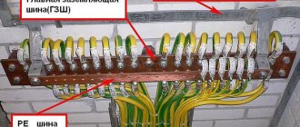
Copper for grounding bus in reel
According to the Electrical Installation Rules (abbreviated as PUE), grounding devices can be not only steel, but also copper. Moreover, copper is the best option, since this metal has excellent electrical conductivity, is slightly oxidized under the influence of voltage, and is not subject to rust. It should be noted that steel is used much more often for the manufacture of grounding bars, but this is due to its lower price. It is not recommended to make grounding strips from aluminum, since this metal quickly corrodes and is characterized by insufficient resistance.
Note! The main grounding bus is characterized by a smaller cross-sectional area compared to the protective wire or neutral of the working wire of the power line.
For the PE bus in electrical installations up to 1000 V, the cross-section of the conductors must be different depending on the metal. In the case of a copper conductor, the cross-section must be more than 10 square millimeters, for aluminum this figure is 16 square millimeters, and for steel - 75 square millimeters.
A nineteen-inch copper grounding bus must provide areas for simultaneous connection of 14 or 18 guides. Thus, there will be from 14 to 18 mounting bolts on one strip. The strip is most often equipped with a pair of insulators and is placed in a special cabinet (the so-called cabinet No. 19) and is connected to the ground loop via a PVZ wire. A nineteen-inch bus is used to connect contacts with a cross-section of 2.5 square millimeters.
According to GOST requirements, the main grounding bus must have at least five simultaneous connections.
The grounding device can be made of copper-plated steel. Sheet thickness is 14.2 millimeters. Such a kit will not be cheap, but it will acquire all the properties characteristic of copper conductors.
Note! Fourteen connectors are usually sufficient for ten or more apartments, provided the load is evenly distributed.
Grounding bars are available in two types - REC-ET2-M and REC-ET. The first model is mounted on special profiles in mounting cabinets. But the grounding bus holder, whose galvanic coating protects the product from corrosion, will not work without a special organizer, with which you can connect up to nine consumers.
Errors when installing memory
Typical disadvantages often encountered in practice include:
- Use as a contour of metal fences or masts. Current resistance is not taken into account and creates the risk of severe electric shock to people in the event of an accident in the system.
- Connecting the circuit directly to the housing of electrical appliances, bypassing the grounding bars in the panel.
- Installation of separate switches in the neutral conductor. If the device fails, electrical appliances may become energized. Sometimes the neutral wire contact is not strong. The consequences are the same.
- Use of products of smaller cross-section or thickness for grounding conductors. Such electrodes quickly fail under the influence of corrosion.
- Use as a grounding conductor for the working “zero”. There is an increased likelihood that the system will be energized.
- Location of horizontal grounding conductors on the surface of the earth. In the event of an accident, the affected area will increase.
- Ground connection to the heating pipe. It is impossible to say which direction the stray currents will take, since the situation in the neighboring apartment is unknown. The likelihood of electric shock to strangers increases.
Upon completion of installation work, the system is checked. Attention is drawn to the value of current dissipation resistance. To carry out this work, it is advisable to involve a specialist with the appropriate equipment.
Application
The grounding bus is used as an integral element of the protective circuit when diverting power lines to apartment buildings and industrial buildings. Grounding serves the function of protecting humans and other living organisms from the effects of current when electrical appliances are running. Busbars are used in systems with power up to 1000 V.
The bus is designed to act as a connecting element for many conductors at the same time, and also ensures the operation of the entire grounding system of the structure. The main grounding bus (GGB) is assigned the function of equalizing potential indicators in the electrical network. Thanks to this element, the conductor is separated and the contacts are connected. The contacts transmit electrical discharges, which is required for the normal functioning of individual systems in the building.