My bitter experience as an electrician allows me to say: If your “grounding” is done properly - that is, in the panel there is a place for connecting the “grounding” conductors, and all plugs and sockets have “grounding” contacts - I envy you, and you have nothing to worry about worry.
Grounding connection rules
What is the problem, why can’t you connect the ground wire to heating or water supply pipes?
In reality, in urban conditions, stray currents and other interfering factors are so great that anything can end up on the heating radiator. However, the main problem is that the tripping current of the circuit breakers is quite high. Accordingly, one of the options for a possible accident is a short-circuit breakdown of a phase to the housing with a leakage current just somewhere on the border of the machine’s operation, that is, at best 16 amperes. Total, we divide 220V by 16A - we get 15 ohms. Just some thirty meters of pipes, and you get 15 ohms. And the current flowed somewhere, towards the uncut forest. But that doesn't matter anymore. The important thing is that in the neighboring apartment (which is 3 meters away, not 30, the voltage on the tap is almost the same 220), but on, say, a sewer pipe there is a real zero, or so.
And now the question is - what will happen to the neighbor if he, sitting in the bathroom (connected to the sewer by opening the plug) touches the tap? Did you guess it?
The prize is prison. Under an article about violation of electrical safety rules that resulted in casualties.
We must not forget that you cannot imitate a “grounding” circuit by connecting “zero working” and “zero protective” conductors in a European socket, as some “craftsmen” sometimes practice. Such a replacement is extremely dangerous. Cases of burning out of the “working zero” in the shield are not uncommon. After this, on the body of your refrigerator, computer, etc. 220V is placed very firmly.
The consequences will be approximately the same as with a neighbor, with the difference that no one will be held responsible for this except the one who made such a connection. But as practice shows, this is done by the owners themselves, because... They consider themselves sufficient specialists not to call electricians.
“Grounding” and “grounding”
One of the options for “grounding” is “grounding”. But not as in the case described above. The fact is that there is a zero potential on the switchboard body on your floor, or more precisely, the neutral wire passing through this very switchboard simply has contact with the switchboard body through a bolted connection. Neutral conductors from the apartments located on this floor are also connected to the shield body. Let's take a closer look at this point. What we see is that each of these ends is threaded under its own bolt (in practice, however, these ends are often connected in pairs). This is where we need to connect our newly made conductor, which will later be called “grounding”.
This situation also has its own nuances. What prevents the “zero” from burning out at the entrance to the house. Actually, nothing. We can only hope that there are fewer houses in the city than apartments, and therefore the percentage of occurrence of such a problem is much lower. But this is again a Russian “maybe”, which does not solve the problem.
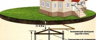
The only correct decision in this situation. Take a metal corner 40x40 or 50x50, 3 meters long, hammer it into the ground so that they don’t stumble over it, namely, dig a hole two shovel bayonets deep and drive our corner there as much as possible, and from it draw a PV-3 wire (flexible , stranded), with a cross-section of at least 6 mm. sq. to your switchboard.
Ideally, the “grounding loop” should consist of 3 – 4 corners, which are welded with a metal strip of the same width. The distance between the corners should be 2 m.
Just don’t drill a hole in the ground with a meter-long drill and lower the pin there. It is not right. And the efficiency of such grounding is close to zero.
But, as with any method, there are downsides. You are, of course, lucky if you live in a private house, or at least on the first floor. But what about those who live on the 7th-8th floor? Should you stock up on 30-meter wire?
So how to find a way out of this situation? I’m afraid that even the most experienced electricians will not give you the answer to this question.
What is required for house wiring
For wiring around the house, you will need a copper grounding wire of appropriate length and a cross-section of at least 1.5 mm. sq. and, of course, a socket with a “grounding” contact. Box, plinth, bracket - a matter of aesthetics. The ideal option is when you are doing renovations. In this case, I recommend choosing a cable with three cores in double insulation, preferably VVG. One end of the wire goes under the free bolt of the distribution board bus connected to the panel body, and the other end goes to the “grounding” contact of the socket. If there is an RCD in the panel, the grounding conductor should not have contact with the N conductor anywhere on the line (otherwise the RCD will trip).
How to connect grounding in a panel
It’s hard to imagine coziness and comfort in a private house or apartment without an established power supply system. Electricity consumption is constantly increasing, making it more difficult to protect people and pets from electric shock. Risks can be eliminated and the consequences of injuries can be minimized using a grounding system that connects points of the electrical network or energy consumer to a grounding structure.
How to connect zero and ground in an electrical panel and in what cases is this necessary?
How to correctly connect neutral and ground in the electrical panel of a private house or apartment.
Why do you need to connect the neutral wire to ground? What does the PUE say? When designing the power supply of buildings and structures, which include both working and protective grounding, the likelihood of voltage dangerous to the life and health of people appearing on the conductive (metal) housings of devices and equipment must be minimized. In this article we will talk about how to connect zero and ground and why it is needed. For those who are not interested in the preface and theory, the practical implementation is described at the end of the article. Content:
- Types of protection against electric shock
- Grounding systems
- Differences between grounding and grounding
- How to properly connect zero to ground
Design and purpose of grounding devices
Such structures are divided into working and protective devices.
- The worker is used to organize the safe operation of industrial units. Also common in private households.
- A protective grounding system is required for electrical networks in the residential sector.
Installation of a grounding device (GD) is required in accordance with the Rules for the Construction of Electrical Installations and the Rules for the Operation of Consumer Electrical Installations.
People touching live parts exposed as a result of improper operation of electrical equipment, design defects, deterioration of insulation and other reasons is common. Poor-quality design of the charger and its installation can lead to serious consequences for people: electric shock, burns, disruption of the heart and other human organs, electric shock often leads to amputation of limbs, disability and even death.
The grounding system consists of external and internal parts, which are joined in the electrical panel. An external grounding device consists of a complex of metal electrodes and conductors that drain emergency current from electrical equipment into the ground in places that are safe for people. The electrodes are called ground electrodes. Electrical conductors are grounding conductors; they are pins 1.5 m long and 1 mm in diameter.
They are manufactured industrially from copper or copper-plated steel. Their main advantage is increased current conductivity. They are driven into the ground with hammers or sledgehammers to a depth of 50 cm; contact with the ground must be as strong as possible, otherwise the structure’s ability to drain current will deteriorate.
The simple design is made from a single electrode. Used in lightning rods or to protect remote objects and equipment. In individual farms, preference is given to multi-electrode devices. They are placed in one row and are called linear memory profiles. The standard chain length is 6 meters. They are connected to each other using brass couplings; the fastening is threaded; welding is not recommended. Grounding conductors are installed through terminals. Twisting and soldering of cores are excluded.
A device such as a ground loop (closed version) is still common. It is constructed at a distance no closer than 1 meter and no further than 10 meters from the house. Placed in a trench in the form of an equilateral triangle. Side length 3 m, depth – 50 cm, width – 40 cm. Grounding conductors are driven into the corners. The same operation is performed with other vertical electrodes (no more than five units). Grounding conductors in the lower supporting part are welded to horizontal products.
They are made of copper, copper or zinc coated steel angle (5 mm flange, 40 mm strip). A standard stainless steel angle of any profile is often used. The products are not painted, as in this case the electrical properties will deteriorate due to weakened contact with the ground.
The design of the circuit is simple; you can do it yourself. But the work is simplified when using ready-made grounding devices on the market, complete with grounding wires. Financial losses will be recouped through the use of high-quality materials that are resistant to corrosion and have a long service life.
The main elements of the grounding connection diagram for a country house and the rules for their implementation
The grounding connection diagram in a country house is as follows: electrical appliance - socket - electrical panel - grounding conductor - ground loop - ground.
The connection begins with the installation of a grounding device in the local area in accordance with the rules defined in Chapter 1.7 of the PUE, 7th edition. The ground electrode is a metal structure that has a large contact area with the ground. Designed to equalize the potential difference and reduce the potential of grounded equipment in the event of a short circuit to the housing or the appearance of excess voltage in the electrical network. The design and depth of its installation is determined based on the soil resistance in the area (for example, dry sand or wet black soil).
From the grounding device (grounding) made on the site, we lay a grounding conductor, which is connected to the main grounding bus using a bolted connection, clamp or welding. We select a conductor with a cross-section of at least 6 mm2 for copper and 50 mm2 for steel, and it must meet the requirements for protective conductors specified in Table 54.2 of GOST R 50571.5.54-2013, and for the TT system have a cross-section of at least 25 mm2 for copper. If the conductor is bare and laid in the ground, then its cross-section must correspond to that given in table 54.1 of GOST R GOST R 50571.5.54-2013.
In the electrical panel, the grounding conductor is connected through a grounding bus to protective conductors laid to sockets that have a grounding contact and other electrical receivers in the house. As a result, each electrical appliance is connected to the grounding system.
Connecting the external part of the charger to the shield
To determine the exact procedure for connecting the grounding to the panel, knowledge of the method of using the neutral is required. It can be isolated and grounded. The insulated core is used in networks with increased voltage values of 3-35 kV. With a power supply of 380 V and 220 V, both options work effectively. However, the new PUE rules require the neutral to be grounded. The circuits must be built for voltages up to 1000 V.
Popular grounding systems are TN-C, TN-S, TN-CS. Two-phase TN-C is outdated, but is still used in buildings that have a long service life. Their replacement is associated with technical and financial difficulties. In this circuit, the neutral conductor is used as a protective ground wire. From a practical point of view, for residents of apartments and houses, cable and conductor products with 4 cores are beneficial: their cost is lower and installation work is simpler.
The question of how to connect grounding in a multi-storey building is of interest. The conductors are connected to the common memory bus. The bus is then routed to the electrical panel housing on the floor. The process of converting TN-C to TN-CS in the home panel is similar. The idea is to connect the neutral protective conductors to a single bus of the charger and then attach it with a jumper to the zero bus.
The main disadvantage is associated with the risk of damage to the neutral wire. Then the grounding structure will become unusable. Regulatory documents have introduced a ban on the use of TN-C in new buildings. But it will take decades to completely replace the system.
The principle of operation of TN-S is based on the fact that the zero operating and protective lines are supplied to the consumer by separate conductors from the transformer substation. In the Russian Federation and CIS countries, an intermediate version of TN-CS is common, in which the conductors are separated directly upon entry into the house. In both options, the safety functions are performed by a residual current device (RCD).
Dependence of the connection diagram on the type of grounding system
Grounding of residential buildings is carried out using the following systems: TN (subsystems TN-C, TN-S, TN-CS) or TT. The first letter in the name indicates the grounding of the power source, the second - the grounding of open parts of electrical equipment.
The subsequent letters after N indicate the combination in one conductor or the separation of the functions of the zero working and zero protective conductors. S - zero working (N) and zero protective (PE) conductors are separated. C - the functions of the neutral protective and neutral working conductors are combined in one conductor (PEN conductor).
Electrical safety is fully ensured when a decrease in the resistance of the ground electrode does not entail an increase in the ground fault current. Let's consider how the grounding connection diagram depends on the electrical network system implemented at the facility.
Grounding system TN-S
Figure 1. TN-S system
At facilities equipped with an electrical network using the TN-S system, the neutral working and protective conductors are separated along the entire length, and in the event of a phase insulation breakdown, the emergency current is discharged through the protective PE conductor. RCD devices and automatic circuit breakers, which react to the occurrence of current leakage through the protective zero, disconnect the network with the load.
The advantage of the TN-S grounding subsystem is the reliable protection of electrical equipment and people from damage by emergency current when using electrical networks. Due to this, this system is considered to be the most modern and safe.
To carry out grounding using the TN-S system, it is necessary to lay a separate grounding wire from the transformer substation to your building, which will lead to a significant increase in the cost of the project. For this reason, the TN-S grounding subsystem is practically not used for grounding private sector facilities.
TN-C grounding system. The need to switch to TN-CS
Figure 2. TN-S system
Grounding using the TN-C system is most common for old residential buildings. The advantage is that it is cost effective and easy to implement. A significant drawback is the absence of a separate PE conductor, which eliminates the presence of grounding in the sockets of a country house and the possibility of equalizing potentials in the bathroom.
Electric current is supplied to suburban buildings via overhead lines. Two conductors are suitable for the structure itself: phase L and combined PEN. It is possible to connect grounding only if there is three-wire wiring in a private house, which requires converting the TN-C system to TN-CS by separating the neutral working and neutral protective conductors in the electrical panel (see clause 1.7.132 of the PUE, 7th edition) .
Grounding connection using the TN-CS system
The TN-CS grounding subsystem is characterized by the combination of the neutral working and neutral protective conductors in the area from the power lines to the entrance to the building. Grounding according to this system is quite simple in technical design, due to which it is recommended for wide use. The disadvantage is the need for constant modernization in order to avoid breakage of the PEN conductor, as a result of which electrical appliances may be exposed to dangerous potential.
Let's consider the grounding connection diagram in a country house using the TN-CS system using the example of a transition to it from the TN-C system.
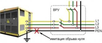
Figure 3. Main distribution board diagram
As already noted, to obtain three-wire wiring, it is necessary to correctly separate the PEN conductor in the distribution panel of the house. We start by installing a busbar into the electrical panel, ensuring a strong metal connection with it, and connecting the combined PEN conductor coming from the side of the power line to this busbar. We connect the PEN bus with a jumper to the next installed PE bus. Now the PEN bus acts as the bus of the zero working conductor N.
Figure 4. Ground connection diagram (transition from TN-C to TN-CS) Figure 5. TN-CS ground connection diagram
Errors when installing memory
Typical disadvantages often encountered in practice include:
- Use as a contour of metal fences or masts. Current resistance is not taken into account and creates the risk of severe electric shock to people in the event of an accident in the system.
- Connecting the circuit directly to the housing of electrical appliances, bypassing the grounding bars in the panel.
- Installation of separate switches in the neutral conductor. If the device fails, electrical appliances may become energized. Sometimes the neutral wire contact is not strong. The consequences are the same.
- Use of products of smaller cross-section or thickness for grounding conductors. Such electrodes quickly fail under the influence of corrosion.
- Use as a grounding conductor for the working “zero”. There is an increased likelihood that the system will be energized.
- Location of horizontal grounding conductors on the surface of the earth. In the event of an accident, the affected area will increase.
- Ground connection to the heating pipe. It is impossible to say which direction the stray currents will take, since the situation in the neighboring apartment is unknown. The likelihood of electric shock to strangers increases.
Upon completion of installation work, the system is checked. Attention is drawn to the value of current dissipation resistance. To carry out this work, it is advisable to involve a specialist with the appropriate equipment.
Types of protection against electric shock
In accordance with paragraph 1.1 of GOST 12.1.030-81, protective grounding or grounding (zero-ground connection) is designed to protect people from electric shock in the event of insulation damage when they touch metal non-current-carrying parts of electrical equipment.
Grounding is an intentional or accidental electrical connection of metal parts of electrical equipment, electrical installations, or a network point to a grounding device, busbar or other protective equipment (clause 01-10-09 GOST R 57190-2016).
This could be reinforcement in the ground, building structures or special electrodes. This measure is a mandatory deliberate protection of both residential and non-residential assets.
Grounding is the deliberate connection of metal parts that are not energized in the normal state with a neutral protective conductor (solidly grounded neutral of a transformer or generator).
In accordance with paragraphs 1.1.2, 1.1.3, 1.7 of GOST 12.1.030-81, grounding must be done by electrically connecting metal parts of electrical equipment to a grounded point of the power supply using a neutral protective conductor (PE).
For neutral protective and grounding conductors, you can use: special conductors, as well as metal structures of buildings and structures.
Protective grounding and grounding of electrical equipment must be carried out without fail when using an alternating current voltage with a nominal value of 220 (1 phase) and 380V (3 phases) and higher and a direct current voltage of 440V and higher. In addition, according to clause 1.7.13 of the PUE, the power supply for electrical receivers must be supplied from a 380/220 V network with a TN-S or TN-CS grounding system.
An example of a metering board with an RCD for a private house | TT grounding system
Installing a selective residual current device (RCD) in the metering panel of a house can significantly improve fire safety. This is especially true if you use a grounding system - TT
In this article we will look at the step-by-step assembly of the metering board diagram for a private house in which an RCD is installed . This assembly complies with the Technical Specifications, which are most often issued by energy supply companies:
– Dedicated power 15 kW
-Input cable – SIP – Self-supporting insulated wire (4 pcs: 3 phases and PEN)
– An additional grounding loop in the area from which a 1x16mm.sq. conductor is laid to the shield.
The circuit is designed for the type of CT grounding , in which the PEN coming from the transformer becomes a working ZERO, and the protective zero (grounding) is taken from an additional circuit mounted on the site. They are not connected to each other anywhere.
We have already considered the option with the TN-CS system, where the neutral and grounding are brought to one point in the shield, only after which they are separated.
All common metering panel assemblies, including those with surge protectors and those with a socket, for different grounding methods, are available HERE.
Why do you need grounding in a private house or apartment?
In simple words, grounding is necessary to protect a person from possible electric shock in an apartment or private house.
The operating principle of protective grounding is the removal of electric current into the ground from metal electrical appliances when they malfunction.
In a new apartment or during the construction of a house, it is necessary to carry out work on laying a grounding cable and connecting it to the “earth circuit”, either a common house or an individual one. Electrical appliances consume a large amount of energy, their cases are metal and conduct current well, so pay particular attention to grounding: washing machines and refrigerators, cooktops and ovens, electric boilers and heating boilers, microwave ovens.
Correct operation of grounding is based on the fact that:
- The potential difference between the grounded object and other current-conducting objects that have their own grounding is reduced to a non-hazardous value.
- In a working electrical network, the appearance of a current leak will lead to rapid operation of the RCD protective device.
- When a current leaks and a grounded conductive object comes into contact with a phase wire, this current must be discharged.
Attention! The grounding loop will work correctly when combined with the use of residual current devices (RCDs). If the device fails, the current on grounded objects will not exceed a dangerous value. The non-working section of the network will be instantly turned off during the response time of the RCD.
From this we can draw conclusions:
- The most dangerous option for humans is when the body of the electrical device is not grounded and there is no RCD.
- If the housing is grounded and there is no RCD, then this option is not safe enough, since with a high resistance of the ground electrode and large fuse ratings, the potential on the grounded conductor can reach very high values.
- If the housing is not grounded, but the RCD is installed, current leakage can occur through the body of a person who simultaneously touches the faulty device and an object that is naturally grounded. The RCD disconnects a section of the network as soon as a leak occurs. But a person will receive only a short-term electric shock that does not cause harm to health. But the RCD may be faulty, so it’s better not to risk it and do everything according to the next option.
- The device body is grounded and an RCD is installed. This is the best option, since two protective solutions are implemented.
Housing installation
When installing outside the home, it is recommended to use steel electrical panels (No. 1 in the image), which can be locked. The degree of protection from dust or moisture must be at least IP54.
Typically, the shield is mounted at the boundary of the site, for example, on a power line support, a building wall or a fence. Depending on the ease of access to it for inspectors. It is best to bring wires and cables inside for switching, preferably from below, using sealed leads. This way you will ensure maximum tightness and significantly protect the electrical installation as a whole.
All modern switchboard equipment is mounted on DIN rails. Make sure that the shield you purchase has them installed or included. Otherwise, you will have to buy an additional DIN rail.
How to properly connect zero to ground
Incorrect connection of zero to ground can cause tragedy, instead of protection. In a common house input device (IDU), the combined zero must be divided into working and protective conductors. Then the protective zero should be routed to the shields on the floors, and then to the apartments.
This results in a five-wire network:
- 3 phases;
- N;
- P.E.
Don't miss: What is a power cable and what does it consist of? Power cable. Power cables. Detailed review
PE must be connected to the third contact of the sockets. In old houses there is a four-wire network:
- 3 phases;
- combined zero
If the PE conductor is made in the form of an aluminum busbar, then its cross-section must be at least 16 mm², if the copper busbar (brass) is at least 10 mm2. This rule is valid for ASU, otherwise you should be guided by the table below. Cross-section of phase conductors, mm2 Smallest cross-section of protective conductors, mm2 S≤ 16 S 16 16 S>35 S/2
Circuit breakers and other disconnecting devices cannot be installed on the PE protective conductor; it must be non-switchable. It is necessary to separate the combined PEN zero before the machines and RCDs, after them they should not be connected anywhere!
Forbidden:
- Connect the protective and neutral contacts in the socket with a jumper, because if the zero is broken, dangerous phase voltage will appear on the housings of household appliances;
- connect the neutral and protective conductors with one screw (bolt) on the busbar in the shield;
- PE and N must be connected to different buses, and each wire from each apartment must be screwed with its own screw (bolt). It is necessary to take measures against loosening of bolts and protecting them from corrosion and mechanical damage (clause 1.7.139 of PUE 7).
This connection is used in modern power supply of residential premises or private houses. Which meets the requirements of PEU-7 (clause 7.1.13) for direct and alternating current networks with a voltage of 220/380 volts. After separation, combining them is strictly prohibited.
In a private house, we often receive two or four wires from overhead power lines. Most often there are 2 situations:
Situation #1 is a good case. Your electrical panel stands on a support, and a re-grounding is driven under it. There are two buses PE and N in the electrical panel. The zero from the support and the wire from the grounding conductor go to the PE bus. There is a jumper between the PE and N buses, from the N bus there is a working zero to the house, from the PE bus there is a protective zero to the house. Buses PE and N can be installed in the house in the distribution board, then the neutral is connected to the ground on one bus in the metering board as in the photo below. The point is to connect the zero and grounding at the input to all RCDs and automatic circuit breakers, and from this point lead the phase, neutral and ground to the consumers.
Such boards are now often assembled when connecting new private houses to the power grid. In this case, the input circuit breaker is installed in phase, the zero from the overhead power line goes directly to the meter, and the division of the zero (connection to the grounding conductor) is made after it. Less often this is done before the meter, but energy sales are often against such a decision. Why? Nobody knows, they argue about the possibility of electricity theft (the question is how?).
Situation No. 2 - The metering board can be either on a support or in the house or on its facade, it doesn’t matter. You have a sealed input machine and a meter, respectively, you have one or three phases and zero. How to make grounding and is it necessary to connect it to zero? If the overhead power line is new, it is necessary. As in the previous case, you will receive a TN-CS system. Then: the zero from the meter is connected to the PE bus, to which is a wire from the ground electrode (which you will make yourself on your site).
If the overhead power line is old, there is no need to connect the neutral and the ground (Chapter 1.7. PUE clause 1.7.59). Make a TT system (without connecting PE to N). In this case, be sure to use an RCD!
In both situations, each wire on the busbars must be tightened with its own bolt - do not put multiple PE or N conductors under one bolt (or screw).
Installation of a box for an input circuit breaker
In order to prevent unauthorized connection, bypassing the electric meter, all switching and protective devices located before it must be closed in boxes (No. 2 in the image) and sealed.
So, during installation, we first install a special housing for the AB (circuit breaker). It differs in that it has “ears” for easy filling. In a three-phase 380V network, the box is installed on at least three modules so that the Circuit Breaker fits there.
TN-CS system in your home
As described above, this is easy to determine - count the number of power wires in the shield, there should be 5. Just be sure to make sure that the zero bus is disconnected from the housing!
Grounding in the apartment in this case is done as follows:
- ⚡
the phase of your power cable is connected to the old place where the old wiring was previously connected. It is not recommended to switch to another phase on your own. As a rule, the load in the entrance is already distributed, and your initiative may affect the voltage imbalance; - ⚡
The zero core is connected to the zero bus. It must be disconnected from the body and not have any connection with it; - ⚡
The ground wire is connected to the housing. Do not connect your wire under bolts where neighboring apartments are already connected. Select a separate mounting location.
If your home has a modern TN-S system, the connection mechanism is the same.
Installation of the machine
The input machine (No. 3 in the image) is installed in a separate housing, which is closed with a casing. Later, representatives of the energy sales company will seal it, install a seal and check it every time readings are taken or control rounds are taken.
For three-phase 380V networks, with an allocated power of 15 kW, the rating of the circuit breaker should be 25A.
DIY grounding device: step-by-step instructions
If you are asking the question: “how to make grounding at the dacha?”, then to complete this process you will need the following tool:
- a welding machine or inverter for welding rolled metal and bringing the circuit to the foundation of the building;
- an angle grinder (grinder) for cutting metal into specified pieces;
- wrenches for bolts with M12 or M14 nuts;
- bayonet and pick-up shovels for digging and burying trenches;
- a sledgehammer for driving electrodes into the ground;
- a hammer drill for breaking up rocks that may be encountered when digging trenches.
In order to correctly and in accordance with regulatory requirements perform a grounding loop in a private house, we will need the following materials:
- Corner 50x50x5 - 9 m (3 segments of 3 meters each).
- Strip steel 40x4 (metal thickness 4 mm and product width 40 mm) - 12 m in the case of one grounding point connected to the foundation of the building. If you want to make a grounding loop along the entire foundation, add the total perimeter of the building to the specified amount and also take a reserve for trimming.
- Bolt M12 (M14) with 2 washers and 2 nuts.
- Copper ground electrode. A grounding conductor of a 3-core cable or a PV-3 wire with a cross-section of 6–10 mm² can be used.
Once all the necessary materials and tools are available, you can proceed directly to the installation work, which is described in detail in the following chapters.
Selecting a location for installing the ground loop
In most cases, it is recommended to install the ground loop at a distance of 1 m from the foundation of the building in a place where it will be hidden from the human eye and which will be difficult to reach for both people and animals.
Such measures are necessary so that if the insulation in the electrical wiring is damaged, the potential will flow to the ground loop and a step voltage may arise, which can lead to electrical injury.
Excavation work
After a location has been chosen, markings have been made (for a triangle with sides of 3 m), and the location for the strip with bolts to be laid out on the foundation of the building has been determined, you can begin excavation work.
To do this, it is necessary to remove a 30–50 cm layer of earth around the perimeter of a marked triangle with sides of 3 m using a bayonet shovel. This is necessary in order to later weld the strip metal to the ground electrodes without any special difficulties.
It is also worth additionally digging a trench of the same depth to bring the strip to the building and bring it to the facade.
Hammering of grounding conductors
After preparing the trench, you can begin installing the ground loop electrodes. To do this, you must first sharpen the edges of a 50x50x5 corner or round steel with a diameter of 16 (18) mm² using a grinder.
Next, place them at the vertices of the resulting triangle and, using a sledgehammer, drive them into the ground to a depth of 3 m. It is also important that the upper parts of the ground electrodes (electrodes) are at the level of the dug trench so that the strip can be welded to them.
Welding work
After the electrodes are driven to the required depth using a 40x4 mm steel strip, it is necessary to weld the grounding conductors together and bring this strip to the foundation of the building where the grounding conductor of the house, cottage or cottage will be connected.
Where the strip will reach the foundation at a height of 0.3–1 moth of earth, it is necessary to weld an M12 (M14) bolt to which the grounding of the house will be connected in the future.
backfilling
After all welding work has been completed, the resulting trench can be backfilled. However, before this, it is recommended to fill the trench with saline solution in the proportion of 2-3 packs of salt per bucket of water.
Afterwards, the resulting soil must be compacted well.
Checking the ground loop
After completing all the installation work, the question arises: “how to check the grounding in a private house?” Of course, a regular multimeter will not be suitable for these purposes, since it has a very large error.
To perform this activity, the F4103-M1 devices, Fluke 1630, 1620 ER clamps, and so on are suitable.
However, these devices are very expensive, and if you do the grounding at your dacha with your own hands, then to check the circuit, an ordinary 150-200 W light bulb will be enough for you. For this test, you need to connect one terminal of the lamp socket to the phase wire (usually brown) and the second to the ground loop.
If the light bulb shines brightly, everything is fine and the grounding circuit is fully functioning, but if the light bulb shines dimly or does not emit a luminous flux at all, then the circuit is mounted incorrectly and you need to either check the welded joints or install additional electrodes (which happens when the electrical conductivity of the soil is low).
Installation of accounting and security devices in the panel
Now it’s time to install all the other elements on the DIN rail. The complete list of equipment required for the panel of a private house is as follows:
1) Steel electrical panel (protection rating IP54 or higher)
2) Box/casing for AV for 3 modules
3) Three-pole circuit breaker 25A
4) Three-phase electric energy meter 380V
5) distribution block for DIN rail
6) Selective RCD from 40A, leakage current 100mA or 300mA
The electricity meter must be three-phase, for 380V networks. Usually electronic, two-tariff is chosen. When choosing a manufacturer, the main guideline is the warranty period; the one with the longest warranty should be taken. Usually a simple one is taken, without unnecessary interfaces, for example, Mercury or Energomera.
The distribution block must have a sufficient number of terminals for the required conductor cross-sections. For the option with a VDT - residual current switch, with CT grounding, you will need:
1 terminal – 16mm.kv – for re-grounding circuit PV1 or PuV (PuGV)
2 terminals of 6mm.kv - for internal conductors used for switching
The fire protection RCD is selected selective - having a delay when triggered. The leakage current can be either 100mA or 300mA.
The choice of the response threshold of the Residual Current Device depends on many factors. Almost any electrical appliance has some leakage and this is normal. If there are many such devices, the total losses can be large.
Based on this, this value is selected. If the housing is small, it is enough to set 100mA. If this is a cottage, with a lot of technology and equipment, then definitely 300mA.
For internal connections in the panel, it is most convenient to use flexible wires PuGV (also called PV-3) 1x6mm.sq. and NShVI tips.
Grounding schemes: which one is better to make?
The grounding system of a private house depends on the type of network connection to it. Most often, it is performed according to the TN-C principle. Such a network is provided by a two-core cable or two-wire overhead line at a voltage of 220 V and a four-core cable or four-wire line at 380 V. In other words, a phase (L) and a combined protective neutral wire (PEN) are supplied to the house. In full-fledged, modern networks, the PEN conductor is divided into separate wires - working or neutral (N) and protective (PE), and the supply is carried out by a three-wire or five-wire line, respectively. Taking into account the above options, the grounding scheme can be of 2 types.
TN-CS system
Provides for dividing the PEN input into parallel conductors. To do this, in the input cabinet the PEN conductor is divided into 3 buses: N (“neutral”), PE (“ground”) and a splitter bus for 4 connections. Further, conductors N and PE cannot contact each other. The PE bus is connected to the cabinet body, and the N-conductor is installed on insulators. The grounding circuit is connected to the bus splitter. A jumper with a cross-section of at least 10 sq. mm (for copper) is installed between the N-conductor and the ground electrode. In further wiring, “neutral” and “ground” do not intersect.
Reference! It is important to consider that this system is effective only when installing an RCD and a differential-type circuit breaker.
TT system
In such a circuit, it is not necessary to split the conductors, because the neutral and earth conductors are already separated in a suitable network. The cabinet simply makes the correct connection. The grounding circuit is connected to the (residential) PE wire.
The question of which grounding system is better does not have a clear answer. The CT circuit is simpler to install and does not require additional protective devices. However, the vast majority of networks operate on the TN-C principle, which forces the use of the TN-CS scheme. In addition, electrical installations with two-wire power supply are often used in everyday life. When the CT is grounded, the housing of such devices becomes energized if the insulation is damaged. In this case, TN-CS grounding turns out to be much more reliable.
Assembling an electrical metering panel with an RCD
connecting the input cable SIP 4x16
First of all, we connect all the large cross-section wires . In our case, these are Self-Supporting Insulated Wires (SIP). Only four pieces. They are all aluminum, with black insulation on the outside. Their markings are made in the form of a continuous colored stripe.
We connect the yellow, green and red conductors to the upper terminals of the input AB - these are three phases. PEN – with a blue stripe, to the zero terminal of the electric energy meter.
Usually these are the two on the far right. You can connect to any of them, they are internally connected.
Earthlings
Next, we connect the grounding conductors to the distribution block. First of all, as the largest, from the circuit mounted on the site. There is also grounding of the current-conducting body of the shield, which is mounted under a special bolt.
It is this connection scheme of N and PE that distinguishes the TT system from others.
In the TN-CS system, the metering board diagram with an RCD, which we have already reviewed HERE, everything is done differently. There, on the contrary, both the PEN conductor and the grounding loop of the house are combined in the distribution block. And only after that they share.
Here, the input SIP with a blue stripe - PEN, is essentially the working zero “N” of the entire electrical installation. The protective zero, also known as “PE” grounding, is taken from a circuit mounted in the yard.
How to make grounding in an apartment if there is none?
The most optimal solution to the problem is to have a ready-made terminal in the distribution panel. Then it is enough to provide a grounding wire at the wiring installation stage and connect it to the existing building’s own circuit or to the grounding from the line.
1. Installation of RCD.
If the electrical wiring of the riser at the construction stage did not provide grounding for apartments, then a protective device can be connected to protect against potential contact with the housing of electrical appliances. In an apartment, an RCD is relevant for powerful devices with a metal body (water boilers, washing machines, dishwashers, etc.), so it can be connected selectively. However, if there is no individual grounding wire, the RCD will of course be triggered by leakage currents, but you will not be able to rebuild full-fledged protection. Because of this, this method may be suitable as a temporary solution until a ground loop is installed for the entire house or apartment.
Wires from the input machine to the meter
The next step is to lay the wires from the lower terminals of the input machine - 3 phases and connect them to the corresponding contacts of the electric energy meter.
We discussed in detail how to connect a three-phase electricity meter, in what order to connect the wires HERE, using the Energomer CE 306 device as an example.
Why is grounding needed?
The power cable installed in city houses, as a rule, does not contain a third core intended for output to the protective circuit. There is a simple answer to the question of how to find out whether or not there is grounding in an apartment. It is necessary to disassemble one of the power sockets and make sure that there is a third grounding terminal with a yellow-green insulated wire suitable for it. In its absence, the operation of household appliances with ungrounded metal parts is associated with increased danger.
Example of the need for grounding
When answering the question why grounding is needed, it is necessary to consider the following situations. When operating a washing unit, for example, the insulation of a phase wire may be damaged due to chafing or overheating. If it is laid next to metal parts of the structure, then during strong vibrations their accidental contact is possible. The consequence of this is that a dangerous potential reaches the body of the machine without grounding, touching which a person will receive an electric shock.
Example of the need for grounding
Please note: A similar situation occurs in the bathroom, which in addition to the washing unit has a metal or cast iron bathtub.
When the insulation of a phase wire in a bathroom is destroyed due to high humidity, the risk of electric shock increases many times over. Anyone who is aware of the potential threat of phase breakdown on the housing does not need to explain why it is necessary to ground electrical equipment housings.
Role of grounding
Electricity was discovered more than two hundred years ago. During this time, it not only took root in our society, but also became an absolutely irreplaceable part of it.
Technological progress has developed incredibly quickly over the past 20-30 years, resulting in the emergence of a huge number of electrical appliances and devices that are either necessary in our lives or simply make it more comfortable
A grounding circuit is needed so that all these electrical utensils work normally and are not a direct source of danger.
If the network is made correctly, when such problems occur, the residual current device is triggered.
Conventional electrical devices should not create such problems. Serious problems in the electrical circuit of a home are usually associated with large household appliances - refrigerators, washing machines, microwaves, ovens, and so on.
Roughly speaking, equipment that can use over 500 watts in operating mode falls into this category.
If banal lamps can easily get by with the protection inside the socket, which is not always present, then for large household appliances a direct connection to the grounding line is usually a more preferable option.
If you look at a photo of grounding in a private house, you will notice that it must pass through all floors and have access to all necessary electrical devices.
This is why electricians recommend installing a separate grounding line in all rooms in the house, in case there are devices in them that need it.
A simple example is a microwave. Microwaves are now found in almost all homes. The device is quite simple, but it makes life noticeably more convenient and comfortable, and its price is quite affordable, depending on the model and manufacturer.
At initial power, no one usually uses a microwave, but few people know that it is a type of equipment that needs to be grounded.
For what? If you don’t do a simple grounding with your own hands for the microwave, during operation it will create a fairly strong background, which negatively affects the health of others - people, animals, plants.
Some may have noticed that indoor plants grow extremely poorly next to a microwave that does not have a ground.
Another example is a washing machine. They are also found in every home and also have a high electricity consumption.
After reading the instructions for a washing machine, people usually immediately begin to think about how to make grounding. Those who do not read the instructions and do not do the grounding, after a while begin to notice that if you touch it with a wet hand while the washing machine is running, you feel a slight electric shock.
In addition to such discomfort, there may also be problems inside the machine itself, which ultimately lead to a breakdown, for which you will have to pay.
Computers should also be connected to at least grounded outlets. Inside the computer case, a technically complex ecosystem of parts operates, and often all this happens with a large consumption of electricity.
What types are there
First of all, you need to understand for what purpose the grounding needs to be installed. The decisive factor in making a decision will be the voltage class in a private home (220 V or 380 V).
According to its purpose, there are two types of grounding: protective and working.
Working - performed to prevent a sudden increase in voltage in household electrical appliances. This can happen as a result of a violation of the insulation of the transformer windings. This type of grounding also protects electrical appliances from lightning striking the building structure. In this case, the entire charge goes into the ground.
Protective grounding is carried out by forcibly connecting the housing of an electrical device to the ground through a conductor.
The following household appliances must be provided with protective grounding:
- washing machine - its body has a relatively large electrical capacity due to operation in conditions of high humidity.
- microwave oven - the main working element of the oven is the magnetron. It has great power. If the contact with ground in the outlet is poor, then an increase in the level of magnetic radiation may occur. Many manufacturers of microwave ovens equip a grounding terminal on the back of the oven.
For contact between the grounding conductor in the network and the electrical appliance, modern sockets are equipped with grounding contacts.
Grounding in a household electrical network
There are six grounding systems to provide grounding. In individual building structures, in particular residential buildings, two main grounding systems are used.
The TN-SC system has been recommended for implementation in recent years. The following scheme was made with a solidly grounded neutral at the substation. The equipment in this case has direct contact with the ground. The earth (PE) and neutral/zero (N) are connected to the consumer itself by one conductor (PEN). At the entrance to the electrical network of a private house, such a conductor is divided into two independent conductors.
Such a system does not require the installation of a residual current device (RCD). Protection is provided by automatic switches.
The disadvantage of such a system is that if the PEN conductor is damaged or burned out along the substation/house section, phase voltage appears on the grounding bus of the house. This voltage cannot be turned off by anything. Based on this, the PUE regulates strict requirements for such a line: the PEN conductor must be provided with mechanical protection, and periodic local grounding must also be equipped on the power line supports.
Many power lines, especially in rural areas, do not meet the above conditions. For such a case, another grounding system is recommended - the TT system.
Schematic diagram
This grounding system is implemented through a separate wire from the grounding loop to the input panel of the building, and not from the transformer substation. This system is more resistant to damage to the protective conductor, but requires the installation of an RCD. Without equipping the system with such devices, there is no protection against electric shock. In this regard, the PUE recommends such a system only as an addition to the TN-SC system. (If the line does not meet the requirements of the TN-SC system).
General form
Ground loop materials
For the grounding of a private house to be effective, its resistance should not be more than 4 ohms. To do this, it is necessary to ensure good contact of the grounding conductors with the ground. The problem is that grounding resistance can only be measured with a special device. This procedure is carried out when putting the system into operation. If the parameters are worse, the act is not signed. Therefore, when doing the grounding of a private house or cottage with your own hands, try to strictly adhere to the technology.
Example of grounding for a private house
Pin parameters and materials
Grounding pins are usually made of ferrous metal. Most often, a rod with a cross-section of 16 mm or larger or a corner with parameters 50 * 50 * 5 mm (5 cm shelf, metal thickness - 5 mm) is used. Please note that reinforcement cannot be used - its surface is hardened, which changes the distribution of currents, and in addition, in the ground it quickly rusts and collapses. What is needed is a rod, not reinforcement.
Possible electrode profiles
Another option for arid regions is thick-walled metal pipes. Their lower part is flattened into a cone, and holes are drilled in the lower third. To install them, holes of the required length are drilled, since they cannot be driven in. When soils dry out and grounding parameters deteriorate, a saline solution is poured into the pipes to restore the dissipative capacity of the soil.
The length of the grounding rods is 2.5-3 meters. This is sufficient for most regions. More specifically there are two requirements:
- the grounding loop rod must extend into the ground below the freezing level by at least 60 cm (preferably 80-100 cm);
- in arid regions, at least 1/3 of the ground electrode should be in wet soils, so you also need to focus on the level of groundwater - if it is low, longer rods may be needed.
The most commonly used steel angle and strip
Specific grounding parameters can be calculated, but the results of a geological study are required. If you have any, you can order a calculation from a specialized organization.
What to make metal connections from and how to connect them with pins
All pins of the circuit are connected to each other by metal bonding. It can be made from:
- copper wire with a cross-section of less than 10 mm2;
- aluminum wire with a cross-section of at least 16 mm2
- steel conductor with a cross-section of at least 100 mm2 (usually a strip of 25 * 5 mm).
Most often, the pins are connected to each other using a steel strip. It is welded to the corners or heads of the rod. It is very important that the quality of the weld is high - this determines whether your grounding will pass the test or not (whether it will meet the requirements - resistance less than 4 ohms).
Parameters that must be achieved when making a ground loop yourself
When using aluminum or copper wire, a large cross-section bolt is welded to the pins, and the wires are already attached to it. The wire can be screwed onto a bolt and pressed with a washer and nut, or the wire can be terminated with a connector of a suitable size. The main task is the same - to ensure good contact. Therefore, do not forget to strip the bolt and wire to bare metal (can be treated with sandpaper) and tighten well - for good contact.