What does voltage drop mean?
Drop occurs when load transfer occurs throughout the entire electrical circuit. The action of this load directly depends on the tension parameter in its nodal elements. When the cross-section of the conductor is determined, it is important that its value must be such that during the load it remains within certain limits, which must be maintained for the normal operation of the network.
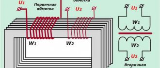
Mnemonic diagram for Ohm's law
Moreover, the resistance characteristics of the conductors that make up the circuit cannot be neglected. It is, of course, insignificant, but its influence is very significant. The drop occurs when current is transferred. That is why, in order for, for example, a motor or lighting target to operate stably, it is necessary to maintain an optimal level; for this, the electrical circuit wires are carefully calculated.
Important! The limit of the permissible value of the characteristic in question differs from country to country. This cannot be forgotten. If it falls below the values specified in a particular country, wires with a larger cross-section should be used.
Any electrical appliance will work fully if it is supplied with the value for which it is designed. If the wire is taken incorrectly, it will cause large voltage losses and the equipment will operate with reduced parameters. This is especially true for direct current and low voltage. For example, if it is 12 V, then a loss of one or two volts will already be critical.
You might be interested in what power is the 16a machine designed for?
Ohm's law for a circuit section
Permissible voltage drop in the cable
The value of electrical voltage loss is regulated and standardized by several rules and instructions for the design of electrical installations. Thus, according to the rule SP 31-110-2003, the total voltage loss from the input point in the room to the electricity consumer furthest from it should not be more than 7.5%. This rule applies to all electrical circuits with a voltage of no more than 400 volts. This rule is used when installing and designing networks, as well as when checking them by Rostechnadzor services.
Important! This document also summarizes the voltage deviation in single-phase household current networks. It should be no more than 5% during normal operation and 10% after an emergency. If the network is low-voltage, that is, up to 50 volts, then +-10% is considered a normal drop.
For power supply cables, rule RD 34.20.185-94 is used. It allows a loss parameter of no more than 6% if the voltage is 10 kV and no more than 4–6% at an electrical voltage of 380 volts. In order to simultaneously comply with these rules and instructions, losses of 1.5% are achieved for low-rise buildings and 2.5% for high-rise buildings.
Voltage drop across resistor
Electrical lighting circuits
To understand how voltage losses affect the design of electrical systems, you should first analyze in detail the block diagram of a conventional lamp. The lighting connection diagram usually includes 4 separate elements. The power supply begins from the transformer substation, from which electrical energy will be transmitted to the owner’s facility. From the transformer, electricity passes to the input and distribution house electrical panel, and from it to a separate panel for the lighting system. Only after passing the described path does the electrical energy finally reach the final consumption device, in our case, a lighting device.
Between every two circuit elements described, a voltage level drop of a certain magnitude occurs. To determine the overall level of voltage loss, use the formula:
∆U=∆U0+∆U1+∆U2
Here, ∆U is the overall loss level, ∆U0 is the voltage loss between the transformer and the input device, ∆U1 is the loss between the input device and the lighting panel, ∆U2 is the loss between the panel and the end consumer.
The loss characteristic obtained during the calculations is compared with the permissible parameters described in the current regulatory documentation. GOST standards indicate that during normal operation of a transformer substation, the total voltage level loss from the transformer to the final lighting device should not exceed 7.5%. Moreover, the level of voltage losses between the elements of the electrical network inside the facility should not exceed 4%.
Thus, in the described formula, the value of ∆U should not exceed 7.5 percent. Inexperienced designers often have a question about how to distribute the percentage of losses between individual sections of the electrical cable along which losses may occur. Craftsmen should take into account the types and features of transformers when designing powerful electrical systems.
Checking the cable for voltage loss
Everyone knows that the flow of electric current through a wire or cable with a certain resistance is always associated with a loss of voltage in this conductor.
According to the rules of the River Register, the total loss of electrical voltage in the main distribution board to all consumers should not exceed the following values:
- for lighting and signaling at a voltage of more than 50 volts - 5%;
- for lighting and signaling at a voltage of 50 volts - 10%;
- for power consumption, heating and heating systems, regardless of electrical voltage – 7%;
- for power consumption with short-term and intermittent operating modes, regardless of electrical voltage – 10%;
- when starting engines – 25%;
- when powering a radio switchboard or other radio equipment or when charging batteries – 5%;
- when supplying electricity to generators and distribution boards - 1%.
You may be interested in this All about selectivity
Based on this, various types of cables capable of supporting such voltage loss are selected.
Example of a calculator for automating calculations
Calculation of power lines for lighting, formulas
Each lighting project involves a lot of basic calculations. The first and most important of them is lighting. After all, you must admit that without light, neither the designers themselves, nor the builders and electricians will be able to work.
When planning lighting lines, you need to take into account the predicted consumption (the load created by the lighting fixtures). Based on these parameters, the cross-section of power cables and wires, the rated current of the protective switching device, etc. are selected.
Since on the way to the consumer, the material of the conductors creates resistance to electric current - because of this, voltage losses occur. This is especially noticeable when many consumers are connected to one line (of the same lighting, for example), with many distribution and group networks.
As a result, it turns out that the voltage at the input and output of each individual section is noticeably different, and the consumers most remote along the line receive much lower voltage parameters than stated. And at the same time, the distribution does not occur evenly, which negatively affects the operation of all electrical appliances involved.
This is because conductors operating for a long time under a load much higher than the design load begin to function in a constant overload mode. As a result, overheating occurs, and this can cause a short circuit or fire on the line. And all because of the shortcomings of the designers, who did not bother to select the appropriate cross-section of conductors for the rated currents of the circuit breaker.
Therefore, when developing a project, you should always remember that the rated current should never exceed the maximum permissible current values of the conductors. Otherwise, the protective function of the circuit breaker, which protects conductors from overloads, will simply be inactive.
In domestic networks, the percentage of losses is very high - sometimes it reaches up to 10-22% (while in world practice these figures are much lower, amounting to 4-6%). And as a result, the cost overrun created by the loss falls on the shoulders of the end consumers.
You may ask, why are all these calculations needed, especially for objects with low consumption levels? Let us indicate the main reasons why it is necessary to make a preliminary calculation of power (voltage) for a future lighting line: Firstly, based on the obtained total power consumption, the optimal currents with the permissible load on all lighting elements in the circuit are determined. Secondly, based on the degree of heating of the conductors under the influence of calculated maximum permissible currents, the optimal cross-section of power cables and wires for lighting is selected.
Thirdly, based on the obtained cross-sectional value of the power cables (wires) and the long-term maximum load they can withstand, suitable automatic shutdown protective equipment is selected. Fourthly, any calculations are simply necessary to obtain permits and technical conditions from local power distribution organizations. Based on them, the technical commission will make a decision on connecting the facility to a line of appropriate power and permissible load.
Despite the apparent insignificance (or lack of accuracy) of such averaged calculations, they are a necessary condition for the further safe operation of the line, because the optimal elements will be selected initially. As a result, such lines will distribute currents as evenly as possible between all consumers. At the same time, voltage losses from an irrationally distributed load will be reduced.
It is worth noting that in lines with a uniformly distributed load (the same street lamps, for example), the losses will be much smaller than in lines that are not evenly distributed. In this case, coupled with an additional inductive load, the losses may be twice as large. Therefore, the above calculation may be inaccurate.
The first step when designing is to find out what kind of network load the future facility will have. To do this, you first need to calculate the total power of all lighting fixtures that will be powered on a specific section of the line. Having this data, it is possible to determine the design loads (Рн) of lighting of the supply network, as well as inputs into residential (or industrial) buildings.
Before this, you need to determine the power of all lamps in the network. The calculation is made using the following formula:
Jr. = Ms. * Cl.
In this calculation Ms. is the power of the lamps, W, and Cl. – number of lamps, pcs.
The result obtained from the previous formula is subsequently used to determine the loads of the supply lighting line.
The calculation is performed using the formula:
Rn = Ml. *Ksp.*Kp.
where, Ml. – this is the installed design power of all lamps; Xpr. – demand coefficient, reflecting how often lighting electrical equipment is used. It serves as an amendment that must be included in the calculations, because in practice, it is unlikely that all electrical appliances will be turned on at the same time and at full power. This coefficient can be determined empirically - for each individual object, or take a suitable value from the table below:
Calculation factor
The best option is to take the value of Kpr. for 0.95. Kp. – loss coefficient in the ballast control equipment of lamps. (For mercury gas-discharge lamps it is 1.1, for fluorescent lamps – 1.2)
In cases where it is planned to supply mixed power to the facility from future lines - both for lighting and for power loads (the same sockets, for example) - then both types of loads need to be summed up. The calculation for mixed loads looks like this:
Nototal. = But + Nc
where, Nototal. – calculated total load, in kW; But – design load of lighting lines, in kW; Ns – power load, calculated in kW.
To determine the maximum permissible cross-sections of wires that will be used in the lines, you need to calculate what currents will pass through them. So for single-phase lines consisting of two wires, the calculation is made according to the formula:
For two-phase lines consisting of three wires (two phases and zero), the solution will look like this:
In the case of laying three-phase lines consisting of four wires (three phases and zero), the cross-section is determined by the following calculation:
As already mentioned, losses cannot be avoided in any lines - this is a common and, one might say, normal phenomenon. Not only do they occur during the transportation of energy from the supplier to the desired site, but they also increase at the points of its distribution between several consumers. Our task is to select the optimal cross-section of wires in order to reduce the percentage of distributed energy losses as much as possible - to the intervals standardized by the PUE: from 2.5 to 5%. It is also desirable to ensure that the load on the network is distributed evenly.
The basic calculation of losses is made as follows:
The value of active resistance (r0) can be calculated using the formula (it is valid for aluminum or steel wire):
When planning lines several kilometers long, the inductive reactance of the wires (ICR), which directly affects the voltage losses in the networks, must be taken into account. Since at such large distances, energy simply cannot be distributed evenly and without loss. Based on work experience, you can take ISP (in our calculation marked as x0) of aluminum (or copper) wires with a cross-section of more than 95 mm2, in the amount of 0.32 Ohm per 1 kilometer. This value will be correct when the distance between the wires is relatively small (up to 6.0 cm). For wires with a cross-section of 10-25 mm2, an inductive reactance coefficient of 0.44 Ohm/km is used. In this case, a more impressive distance between the wires is allowed - 10.0 cm.
As practice shows, in low-voltage lines used primarily for lighting, it is quite difficult to achieve a uniformly distributed load. Therefore, in this case, it is better to use four wire strands (i.e., install a three-phase line). And then, by redistributing the loads from lighting to phase and neutral wires, and power wires to linear ones, it is possible to more evenly divide the loads between all phases.
For three-phase lines, the calculation of losses occurring in each wire will be performed according to the algorithm presented below, in which the first block characterizes active voltage losses, and the second block characterizes reactive ones.
Let's calculate the lighting line for a hypothetical object as an example. The specified parameters are shown in the diagram.
Calculation parameters
In our case, the same type of lamps (N=12 pcs.), with a power of 400 W, are installed at regular intervals (Int.=6m). Let's calculate the distance (P) to the center of load application for each network^
Р = Р1 + (( Int.*(N – 1)/2),
where P1 is the distance from the panel to the first light bulb in the network.
We substitute the values for calculations: P1 = 15.7 + (6 + ((12-1)/2) = 48.7 meters P2 = 21.4 + (6 + ((12-1)/2) = 54, 4 meters P3 = 23.5 + (6 + ((12-1)/2) = 56.5 meters P4 = 27.3 + (6 + ((12-1)/2) = 60.3 meters
Let us determine the design loads described in the second section (formulas 1 and 2):
Rn = Ml. *Ksp.*Kp.
Since our groups of electrical appliances are of the same type, the value will be the same for all lines:
Рн = (12pcs*0.4 kW) *1.1*1 = 5.28 kW
And then the power of the supply network will be: 5.28 * 0.95 * 4 = 20.1 kW
Now you can determine the load moments (ML) for each network, they are calculated like this:
MN = Рн*Р,
where Рн – design loads, Р – distance.
МН1 = 5.28*48.7=257.1 kW/m МН2 = 5.28*54.4=287.2 kW/m МН3 = 5.28*56.5=298.3 kW/m МН4 = 5.28*60.3=318.4 kW/m
Load moment for the supply network (distance to the panel I=25 m):
MNs = 20.1 * 25 = 502.5 kW/m
The total combined (or reduced) load moment (MNs) for all lines is equal to:
MNs = 502.5+257.1+287.2+298.3+318.4 = 1663.5 kW/m.
Let us now determine what the voltage losses will be for our lines:
Mon = Nn-Nmd-PNs,
where, Np is the rated voltage created during idle operation of the transformer (accepted at 105%). Nmd - the minimum permissible voltage of the most remote light bulbs in the network (take 95%); PNS - total voltage losses - to the network in question, % (we accept 3.56% and 3.64%).
So Mon = 105 – 95-(3.56-3.64) = 2.8%
Let us finally calculate the cross-section of the wire suitable for our lines:
Sp = MNs/(K*Pn)
Sp = 1663.5 / (44*2.8) = 13.5 mm2
We find what currents will pass through our networks:
I = (20.1*103)/ (3*220*0.6) = 50.76 A
We determine the percentage of voltage loss for each network:
P1 = 257.1 /(3*44) = 1.95% P2 = 287.2 /(3*44) = 2.17% P3 = 298.3 /(3*44) = 2.26% P4 = 318.4 /(3*44) = 2.41%
As you can see, the predicted percentage of loss in all cases fits into the norm (up to 5%). Based on the data obtained, you can select the most suitable wire cross-section and currents, starting and control equipment, adjust lamp power, etc. To facilitate the calculation process, many useful applications have been invented that take into account all the described quantities. They will allow you not to recalculate everything manually every time when replacing any component of a lighting project.
When creating a design for lines for lighting networks, you need to ensure that the load voltages are distributed as evenly as possible across them. Then the conductors will heat up less, the percentage of losses and damages will decrease, and the risk of accidents will decrease.
Recommended articles on the topic
How to find the voltage drop and correctly calculate its loss in a cable
One of the main parameters by which tension is calculated is the resistivity of the conductor. Copper or aluminum wires are used for wiring from the station or panel to the room. Their resistivity is 0.0175 Ohm*mm2/m for copper and 0.0280 Ohm*mm2/m for aluminum.
The voltage drop for a 12 volt DC circuit can be calculated using the following formulas:
- determination of the rated current passing through a conductor. I = P/U, where P is power and U is rated voltage;
- determination of resistance R=(2*ρ*L)/s, where ρ is the resistivity of the conductor, s is the cross-section of the wire in square millimeters, and L is the length of the line in millimeters;
- determination of voltage loss ΔU=(2*I*L)/(γ*s), where γ is a value that is equal to the inverse resistivity;
- determination of the required cross-sectional area of the wire: s=(2*I*L)/(γ*ΔU).
Important! Thanks to the last formula, you can calculate the required cross-sectional area of the wire for the load and make a verification calculation of losses.
Table of inductive reactance values
In a three-phase network
To ensure optimal load in a three-phase network, each phase must be loaded evenly. To solve this problem, electric motors should be connected to linear conductors, and lamps should be connected between the neutral line and phases.
The loss of electrical voltage in each wire of a three-phase line, taking into account the inductive resistance of the wires, is calculated using the formula
Calculation formula
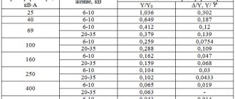
The first term of the sum is the active, and the second is the passive component of the tension loss. For ease of calculations, you can use special tables or online calculators. Below is an example of such a table, which takes into account voltage losses in a three-phase overhead line with aluminum wires with an electrical voltage of 0.4 kV.
Example table
Voltage loss is determined by the following formula:
ΔU = ΔUtable * Ma;
Here ΔU is the voltage loss, ΔUtable is the value of the relative losses, % per 1 kW km, Ma is the product of the transmitted power P (kW) and the line length, kW km.
You may be interested in: Features of capacitor calculation
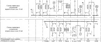
Single line diagram of a three-phase current line
On the chain section
In order to measure the voltage loss on a section of the circuit, you should:
- Take a measurement at the beginning of the chain.
- Perform voltage measurements at the most remote area.
- Calculate the difference and compare with the standard value. In case of a large drop, it is recommended to check the condition of the wiring and replace the wires with products with a smaller cross-section and resistance.
Important! In networks with voltages up to 220 V, losses can be determined using a conventional voltmeter or multimeter.
A basic way to calculate power loss can be an online calculator, which carries out calculations based on the initial data (length, cross-section, load, voltage and number of phases).
Sample calculator for calculating losses
Thus, you can calculate and calculate voltage losses using simple formulas, which for convenience are already collected in tables and online calculators that allow you to automatically calculate the value based on given parameters.
Loss Level Distribution
During the design process of an electrical system, designers must distribute losses between individual sections of the circuit. Experienced craftsmen recommend allocating up to 4% to the section of the circuit from the transformer to the input device. This value of losses is considered optimal, since to ensure a lower level of losses it will be necessary to use an electrical cable with a large cross-sectional diameter, which will have an extremely negative impact on the cost of connecting the facility to electrical networks.
Naturally, the amount of losses in this area should be as low as possible. If in the section from the transformer to the input device the loss value is taken at the level of 4%, then the losses in the electrical system inside the facility should be at a level of no more than 3.5%. Electrical systems of not very long length are created inside electrified objects, therefore the amount of losses on them, when using a cable for a lighting line with a diameter of 1.5-2.5 mm, will be about 2%. Thus, the permissible amount of voltage loss in the electrical network will not be exceeded, and the cost of installing the electrical system will not be too high.
Many young designers may underestimate the importance of proper distribution of electrical voltage losses along the way of transporting electricity from energy facilities of grid companies to the end consumer. This is a pretty serious mistake. First of all, proper distribution allows you to significantly save on electrical cables, due to which the total cost of installing electrical equipment inside the facility can be significantly reduced. In addition, incorrect distribution of losses can lead to a ban on performing electrical installation work on an electrical project if this error is identified by specialists at the stage of approving project documentation. In order for the project to successfully pass the examination stage, designers must be aware of the features of approval of electrical projects.
When determining the level of voltage loss at each section of electricity transportation, specialists must take into account the individual characteristics and characteristics of the object for which the electrical network is being created. In some cases, losses in the area from the transformer to the input device can be set at a level of 6%. This makes sense in situations where a small facility with a low-power electrical system is located at a great distance from the grid company's energy facilities.
You can also find out the cost of electrical design by using the calculator.