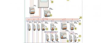
Let us consider the most typical typical circuits of switchgears, which are widely used in the design of substations with a higher voltage of 35-kV. The scheme works as follows.
Each line and transformer are designed to cover all loads of the first category and the main loads of the second category. The need and location for installation of regulatory, protective and compensating devices, current and voltage measuring transformers, current-limiting and arc-extinguishing reactors, as well as their connection diagrams; 1. Operation of the AVR circuit at 6 kV substation VMPE
If the voltage is lost on one of the sections RP2 or RPZ, then sectional switch 1 is automatically turned on and all power to these RPs is transferred to only one source via the remaining power line. In accordance with these requirements, standard diagrams of switchgear devices for 6-kV substations have been developed, which should be used when designing substations.
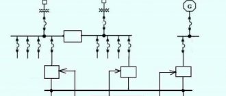
Schemes with bypass bus systems - 12, 12N, 13N and 14 are recommended for switchgear substation with increased requirements for the reliability of power supply of overhead lines, as well as with devices for melting ice in areas with a polluted atmosphere and if periodic cleaning of insulation is necessary, etc. The work established the minimum quantity standard switchgear circuits, covering the majority of cases encountered in practice in the design of substations and switching points and at the same time making it possible to achieve the most economical unified solutions. One of the options for a bridge-type circuit with switches in the line circuits and a repair jumper on the line side is shown in Fig.
It is allowed to use distribution points with a load on their busbars of at least 7 MW at a voltage of 10 kV, and at least 4 MW at a voltage of 6 kV [19].
Power supply for a large enterprise from two independent sources. Deep partitioning of all parts of the system with ATS devices on sectional switches ensures reliability and uninterrupted power supply to consumers of the first category. To increase the reliability of the switchgear, a 9N or 9AN circuit is used with partitioning of the working bus system by the number of transformers and with the connection of each transformer and responsible lines in a partitioning chain of two or three switches to different sections of the buses.
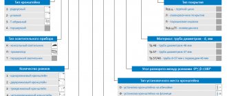
How to read a valve circuit diagram