Graphic section of the EOM
The main components of this section:
- schematic diagram of automatic reserve input (mandatory for consumers of the 1st category);
- diagram of the external lighting system, including transport communications (mandatory for production facilities);
- emergency lighting system diagram;
- implementation schemes for lightning protection and grounding;
- diagram of the internal lighting system;
- diagram of the power equipment system (in residential buildings, as a rule, combined with a lighting system).
For some facilities, such as production facilities, a diagram indicating the locations of electrical equipment installation may be needed.
Design of power supply systems: composition
In accordance with the provisions of current regulations, the development of a power supply project is envisaged in two stages. The first of them (project documentation, “P”) involves the development of drawings and an explanatory note for passing the examination and obtaining a positive expert opinion. The second stage, working documentation (“P”), is developed in accordance with the approved stage “P” and is intended directly for conducting construction and installation work at the site.
In some cases, a preliminary design may be developed, which serves to coordinate the main decisions with the customer, calculate technical and economic indicators and fill out an application for obtaining technical conditions for the power supply of the facility.
When designing power supply systems for buildings and structures, the following is performed:
- schematic diagram of the power supply system (from power sources to power consumers);
- development of solutions for powering electrical receivers according to the classification of the reliability of their operation in normal and emergency modes;
- schematic diagram of working and emergency lighting networks;
- routing cables throughout the building, developing drawings of floor plans and views with the drawing of electrical consumers and cable distributions;
- development of lighting drawings (plans and views);
- calculation of cable lengths and cross-sections, selection of their type;
- drawing up specifications for equipment, products, materials;
- compilation of cable logs;
- reactive power compensation solutions;
- relay protection solutions;
- measures for energy saving, automation and management of the power supply system;
- development of grounding and lightning protection sections;
- preparation and issuance of assignments for the development of related sections and estimates.
Example of documentation for an EOM project section
As an example, let's take a closer look at the lighting diagram in the figure.
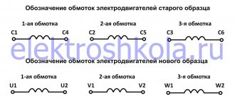
To read the above diagram, you need to understand the graphic symbols; their standard is determined by the standards prescribed in GOSTs 21.614-88 and 21.210-2014. As a rule, on the plan on the right it is indicated what a particular graphic symbol means.
Each individual wiring line is designated by alphabetic and numeric symbols, in the presented plan these are gr1, gr2 and gr3. Groups of luminaires are written in the format AA(B x CC)DD, where AA is the number of lighting fixtures in the group, B is the number of light bulbs in the luminaire, CC is the power in Watts, DD is the safety class of the device.
GOSTs, SNIPs and other regulatory documentation used to develop the EOM section
In the explanatory note to the project, in the “general data” section, it is necessary to indicate the source materials (they were given above) and the regulatory documents on the basis of which the development was carried out. Let's start with GOSTs (numbers are given in the list):
- grounding and resistance standards for stationary installations (464-79);
- list of general technical conditions for electric heating appliances for domestic use (16617-87);
- list of general technical conditions for lamps (17677-82);
- static devices that take into account electrical energy consumption with accuracy classes 1 and 2 (30207-94), as well as 02S and 05S (30206-94); electrical equipment of premises and buildings, list of requirements for special equipment (50571.11-96);
- requirements for equipment and electrical wiring, installation (50571.15-97);
- standard for conventional graphic images on EOM plans (21.614-88 and 21.210-2014).
SNiP numbers:
- for public buildings (2.08.02-89);
- electrical devices (3.06.05-85);
- standards for lighting, both artificial and natural (23-05-95);
- fire safety rules (21-01-97).
In addition, when developing an album of design and construction documentation, it is necessary to take into account the standards given in the Electrical Installation Rules - the “bible” of an electrician.
Justification of the need for a power supply project
In order to create the most efficient and efficient power supply system for any facility, you can attract enormous resources and use the labor of the best specialists, but it will not be possible to achieve your goal without a competent and correctly drawn up power supply project, despite all the efforts and efforts.
The electrical design is the cornerstone of the electrical system, the foundation on which everything rests. When constructing any new facility, be it industrial buildings, residential buildings or cottages, without creating a power supply project it will be impossible to conclude an agreement with the energy supply company and connect it to the power grid.
If the owner of a house or apartment intends to increase the minimum level of allocated power, he will also have to develop a power supply project. If you increase the load on your own, there is a risk of overloading, which can damage the equipment at a minimum, and at a maximum, cause short circuits and fire.
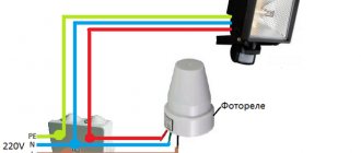
Example of a home electrical project
Back
Forward
Another example of the need for an electrical project is the installation of hidden electrical wiring. Not a single person will be able to accurately remember the locations of the cables and wires of the electrical system, hence there is a fairly serious probability of getting into the wiring when, for example, drilling walls. And having in front of you a visual representation of the electrical wiring diagram, it will not be difficult to avoid this.
Composition of a set of drawings of the EM brand
The EM section contains a description of power electrical equipment systems, internal lighting, lightning protection and grounding.
Each set of drawings has its own designation, for example, XXXX-XX-EM. The number includes a certain digital designation of the design organization and a position on the general plan. But the letters EM indicate to us that this is a set of power electrical equipment.
The main regulatory document on the design and composition of the EM kit is GOST 21.613-88. This document, as well as the instructions given at the end of the article, describe all the requirements in sufficient detail. If you are designing power electrical equipment for the first time, be sure to read these 2 documents.
In 90% of cases, any set of EM includes the following sheets:
- Common data.
- Electrical circuit diagrams.
- Plans for the location of electrical equipment and the laying of electrical networks.
- Cable and pipe magazine.
- Potential equalization system.
Attached documents:
- Specification.
- Questionnaires.
In general, this is the composition of a set of drawings of power electrical equipment.
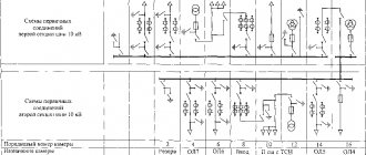
According to GOST 21.613-88, complete transformer substations belong to power electrical equipment, although we always separate them into a separate set of electrical equipment. We draw up all the diagrams, as shown in the example of a transformer substation diagram. Such diagrams are more readable.
In the set of power electrical equipment of the EM drawings brand, we must connect all technological equipment, ventilation, and provide protective electrical safety measures. Electric lighting is not included in this set of drawings. In smaller projects, lighting can be combined with electrical power equipment. In this case, the set of drawings must be assigned the EOM brand.
Regulatory documents on the composition and design of a set of power electrical equipment:
- GOST 21.613-88. Power equipment. Working drawings.
- Electrical working documentation. General requirements and recommendations for composition and design (Replaces VSN 381-85).