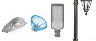
Capacitive photo relay for street lighting is a device that allows you to turn on or off lamps used on roads, at entrances and in parks. Their use saves energy and minimizes inconvenience for drivers, home residents and ordinary passers-by.
The work is based on a photoresistor or photodiode - semiconductor elements that change their parameters depending on the intensity of ambient light. During the day, when there is sufficient light, the light sensor opens the circuit and the lamp turns off, and at night the reverse sequence of actions occurs: the capacitive relay for controlling the lighting reduces the resistance and the light turns on.
Installation of photo relay
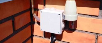
It is not difficult to install a photo relay with your own hands; it is only important to exclude the direct influence of the adjustable light source and protect the device from adverse external influences: moisture, direct sunlight, temperature changes.
For industrial devices, there are a number of standards that such solutions must comply with: GOST (domestic) and IP (international). It is more difficult to ensure that a homemade photo relay is protected from environmental factors, although it is theoretically possible. But for those who want to install such a device in their yard, near their entrance or garage, it is better to first consider the solutions offered on the market - without having the necessary knowledge and experience, it will be extremely difficult to bring the photo sensor to working condition with your own hands.
Connection procedure
Often, photocell sensors are attached to walls using special brackets. They must come with the purchased model. To correctly connect a photo relay to automate street lighting, you need to do the following:
- a connection diagram is usually placed on the device body, which should be studied in detail;
- After you have familiarized yourself with the diagram, you need to choose a suitable location for installation. We talked a little higher about what requirements the installation site must meet;
- connect the wires coming from the bottom of the sensor housing to the lighting fixture;
- after that we set up the photo relay. First, we set the response threshold. To do this, move the regulator to the position we need;
- If you install sensors with an external photocell, do not forget to connect them together using a cable after installation.
If there is a timer in the design of the device, the connection can be made through it. To do this, the timer should be programmed to operate at certain time intervals. This system is very beneficial and convenient for the daylight hours. Thanks to this connection method, quite significant energy savings can be achieved.
Note! The timer has its own memory, which is designed for different periods (from 1 to 12 months). Using a timer can significantly improve the operation of the sensor, making it more correct taking into account the length of daylight hours.
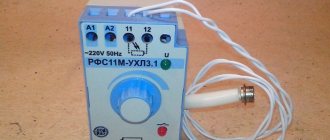
FR-601 (602)
When it comes to using standard single-phase photo relays for lighting, the most popular model is the FR-601 and FR-602 devices manufactured by IEK.
They are quite reliable, and even users uninitiated in electronics have no questions about how to connect an automatic backlight controller. These two modifications have minor differences: they both operate with current of the same voltage and frequency, have similar power consumption (0.5 W) and absolutely identical delivery kits.
The differences relate only to the maximum cross-section of the connected conductors: for the 601 model it is 1.5 square meters. mm., and for 602 - 2.5. Consequently, their rated load current is also different: 10 and 20 A, respectively. Both models have a built-in photocell; it can be adjusted from 0 to 50 lux in increments of 5 lux.
Principle of operation
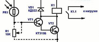
First, let's talk about how this device generally works. The design includes simple elements: a photocell, a phototransistor, a comparator and a relay.
The main task is to monitor the light intensity and, if something happens, close the circuit. As soon as the light intensity decreases, the photocell reacts to this, and it notifies the comparator, which has a response threshold, about this. If the voltage is higher than the set one, a relay is connected and turns on the lamp. Find out how to connect outdoor lights.
How a photo relay works: video
Making at home
The schematic diagram of the FR-602 capacitive photorelay (like its brother) is easily repeated even with little knowledge of electronics. Creating a homemade product becomes especially relevant when there is a need for a large number of devices (for example, to organize automatic switching on and off of lighting depending on the time of day).
For manufacturing you will need the following parts; the designation on the diagram and power will be indicated in brackets:
- 2 bipolar transistors BC857A (Q1 and Q2);
- 5 rectifier diodes 1N4007;
- rectifier diode 1N4148;
- Zener diode 1N4749;
- resistors (R2, R4–R9: 1.5 MΩ, 1 MΩ, 560 kΩ, 200 kΩ, 100 kΩ, 75 kΩ and 33 kΩ; all 0.125 W);
- resistor (R3, 220 Ohm, 2 W);
- photocell (PH, up to 100 kOhm);
- trimming resistor (WL, 2.2 mOhm);
- capacitor (C2, 0.7 µF 400 V);
- electrolytic capacitors (C4–C5, 100 μF 50 V and 47 μF 25 V, respectively);
- relay SHA-24VDC-SA (Rel1).
Considering the set and total cost of parts, as well as the availability of a diagram, model 602 is a fairly simple solution to implement.
By the way, many parts from the list can be replaced with domestic ones. According to reviews from those who have already assembled, the bipolar transistor Q2 can be replaced with the ubiquitous KT3107B, and the zener diode 1N4749 can be replaced with three series-connected D814A or two D814D. The connection diagram is also not particularly complicated.
Connection features
Correct installation location
A photo relay is usually located near the light source, the operation of which it must regulate. This is especially true for outdoor type meetings.
Note! In order for the sensor to work as it should, when connecting it, you need to prevent light from the lamp from reaching the photocell. It would be best to place the device in the shade of a lighting fixture.
Three wires come out of the street lighting sensor housing. They need to be connected correctly to the lamp:
- blue conductor. It is intended for zero. In addition, it is possible to connect a conductor from a lighting device to it;
- brown conductor. This conductor is necessary to connect to the mains power phase;
- red conductor. The sensor is controlled through it. It leads to the lamp from the existing regulator.
In rare cases, which is sometimes typical for a street lighting system, the sensor design requires the presence of an additional conductor - “ground”. With its help, you can prevent voltage from entering the device body. In this situation, the circuit for connecting the photo relay to street lighting will be standard. But the “ground” will be connected to the lamp itself, bypassing the regulator.
Note! Some manufacturers change the markings of conductors.
Therefore, a basic connection diagram is used:
- the phase is always connected to the regulator;
- zero is connected to the regulator and goes to the lamp;
- the phase goes from the regulator to the lamp.
Now, knowing how the photo relay is connected, you see that it will be quite easy to do everything yourself.
Analogs
Among the analogues of this device are the FR-75A - a photo relay, the circuit of which is more complex for manufacturing at home, and is also less stable and durable in practical use.
Among its advantages is a larger range of operating brightness, ranging from 1 to 200 lux, which is four times higher than its competitor. Another big advantage of the FR-75 device is the ability to operate in 12 V DC circuits.
Also, the photosensor is remote, which allows you to install the regulator itself indoors and not worry about environmental factors. In general, the model has no equal in its class and is the best photo relay - 12 volts DC is often used as power for such devices. The device connection diagram is shown in the figure.
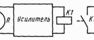
The design and principle of operation of the relay for automatically turning on the light
The main element of devices of this type is a photo relay, the contacts of which close when the illumination decreases to a certain level and open when the level of natural light reaches the specified values. The main elements and operating principle of the photo relay are shown in the following figure.
- housing – it contains all the elements of the device and provides mounting holes or other structural devices;
- photocell - a light-sensitive current sensor that supplies pulses to turn control circuits on and off;
- electronic unit - consisting of: a power module, a signal amplification device and an electromechanical relay.
Various electronic devices that are triggered when light rays hit them can be used as a photocell: phototransistor and photothyristor, phototriac or LED.
High power equipment
Among the competitors, you can also consider the FR-7E photo relay, but the lack of moisture protection (IP40) and rather high power consumption are not in its favor.
Disadvantages also include open contact clamps and lack of protection for the trimming resistor on the front panel. A positive point is that the FR-7 can operate in AC networks of 220 volts with a voltage of up to 5 amperes, which is almost an order of magnitude greater than that of the competitors discussed above. The adjustment range of 10 lux is also set only by a specialist; you cannot adjust it yourself.
In terms of dimensions, the FR-7 also exceeds the photo relays discussed in the article (see drawing).
Main technical characteristics of street light sensors for turning on lights
To automate the operation of street lamps installed near the house, you should choose a photo relay with suitable technical characteristics. Basic parameters include:
- current frequency;
- Rated voltage . It can be 220 V or 380 V. For street lamps near the house, the first type is sufficient. Manufacturers offer photo relays with voltages of 12 V and 42 V, but they find limited use;
- power consumption;
- rated current . Must be related to network capacity;
- temperature range in which the product can be operated, as well as the presence of a sufficient level of protection.
“The level of protection is indicated by IP and two numbers. The first characterizes the degree of dust protection (maximum - 6), the second - moisture protection (maximum - 8). For street lighting, you should choose devices with a protection level of IP44 and higher.”
The technical characteristics of the device must meet the requirements of the system
Motion sensors to turn on the lights. Types, principles of operation, scope of application, selection criteria, recommendations of specialists, review of popular models; details of connection, configuration and operation - read in the publication.
Expert opinion
Viktor Pavlovich Strebizh, lighting and electrical expert
Any questions ask me, I will help!
It is advisable to use a photo relay even with manual lighting control, since you can forget to turn off the light, and the sensor will take care of this on its own. If there is something you don’t understand, write to me!
Where can I buy
If you want to save time, you can purchase the necessary device at your nearest specialty store. The optimal option, in terms of price-quality ratio, remains purchasing from the AliExpress online store. Mandatory long waits for parcels from China are a thing of the past, because now many goods are in intermediate warehouses in destination countries: for example, when ordering, you can select the “Delivery from the Russian Federation” option:
| Photo relay with automatic on/off | Photosensitive module for Arduino | Automatic control module for light switching |
| Street lamp with built-in light sensor | Adjustable photoresistor switch | Wall switch for lighting control |
What is it for?
A photo relay is a device that includes a special sensor that reads the level of illumination of the surrounding space. By connecting such a device to an outdoor lighting system, you can automate the switching on/off of lights and link them to the level of street illumination. This will allow you to significantly reduce energy consumption, ensuring that the lights are turned on only when necessary. But to do this, you need to understand the features of the device for its correct connection and configuration. If everything is done correctly, the sensor will only work when night falls, and when day begins, it will be in sleep mode. In fact, to connect such a device you need to understand the following points:
- what is this sensor;
- what type of photocell is installed in it;
- what is needed to connect it to the electrical network at home.
Let's look at each point in more detail.
Possible malfunctions of the street lighting mechanism
If the photo sensor does not work correctly, the reason most often lies in installation or configuration errors.
First, make sure that there is no street light or high fence in front of the day-night device, maybe the tree has become much taller since installation, or has begun to shade the area more when leaves appear on it. Such obstacles must be removed or the photo relay moved to a more suitable location.
It is also possible that one of the residents of the house accidentally changed the settings, or they became irrelevant with the change of season. Monitor the set light sensitivity and set the response delay to at least 5 minutes.
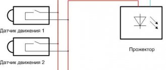
If a motion sensor has recently been added to the system, a false activation may be due to the movement of pets or passers-by on the street.
Often a photo relay malfunction is determined visually
When simple methods do not help, you need to look inside the device. Perhaps moisture got into the case and the contacts oxidized, or as a result of a power surge in the network, one of the board elements burned out. If the damage is not too significant, you should take the device to a workshop and consult about repairs. But if the board is noticeably damaged, you will have to replace the device completely (or just the remote sensor). In a self-made device, you should first check the quality of soldering, and if necessary, replace the failed element.
When the device is fully operational and correctly configured, the reason may lie in the wires connected to it. Carefully check the integrity of the insulation in each section and, if necessary, replace the damaged cable.
If you cannot detect the fault yourself, you must contact the seller (if the device is under warranty) or a manufacturer’s representative.