Purpose
Manually controlled switching devices are designed to turn on/off small load currents.
They apply:
- in AC and DC networks, performing the functions of input switches;
- in switchgears for the purpose of distributing electricity in various electrical installations;
- as manual switches for remote control of asynchronous electric motors.
- Package switches are indispensable at substations, where they are used for the purpose of switching measuring instruments. They facilitate the control of electric power units in electrical circuits, which simplifies the work of drivers.
Previously, package switches were located in each of the distribution boards of an apartment building. Their purpose is to manually cut off power during repair work or when servicing lines.
Despite the displacement of package switches by modern automatic machines, they can often be seen in an apartment electrical panel among more advanced switching electrical devices used for protective disconnection of load wires. This is facilitated by the low price of switches and the ease of their maintenance.
Various models of cam switches can be found on load transfer panels. With their help, it is convenient to remotely control electrical mechanisms.
Advantages
- The advantages of packages include:
- compactness;
- high speed of electric arc suppression;
- minimum care requirements;
- resistance to mechanical damage.
Flaws
The devices cannot withstand frequent switching of increased loads. If they fail, they cannot be repaired. Packers are not capable of protecting electrical wiring from short circuits; they are not sensitive to differential currents, which limits their use as protective devices.
More modern analogues of the device
The old package switches have been replaced almost everywhere with automatic machines. This is logical, because the requirements for energy consumption and durability of devices have changed. Nowadays, RCDs (residual current devices), automatic and differential circuit breakers, and contactors are widely used.
Option #1: residual current device
The device is designed to prevent current leaks. It reacts to differential current, which contributes to overheating of electrical cables, which can lead to a short circuit and fire of the wiring. Leaks can also cause electric shock to a person.
The device cannot be considered a 100% analogue of a bagger, however, when combined with a circuit breaker, it performs even more functions
An RCD must be installed to avoid the risk of electric current leakage if it begins to pass by consumer devices. The device functions as a leak indicator, which simply turns off the electricity in case of problems.
The residual current device itself does not protect against overloads or short circuits. This is only possible if it is connected in combination with a circuit breaker.
Option #2: circuit breaker
These devices replaced the batch switch. They perform the same functions, but are more convenient to use, durable and wear-resistant.
Automatic switches can also be one-, two-, three-, four-pole. They differ in the type of drive (it can be manual, spring, motor), type of connection and other technical and operational characteristics.
A selective circuit breaker does not require additional power to make or open its contacts. The device is electro-mechanical and is designed to perform its functions in the best possible way.
Circuit breakers offered for sale are marked and classified in accordance with GOSTs 9098–78 and 14255. These documents establish requirements for the technical characteristics of devices.
Option #3: differential machine
This is a combined machine that simultaneously performs the functions of two devices - an RCD and a circuit breaker. The differential automatic machine perfectly replaces the packetizer, is suitable for household electrical networks and is successfully used in enterprises.
Differential circuit breaker is a “2 in 1” device: a circuit breaker and an RCD located in a common housing. It flawlessly copes with the tasks of both devices and at the same time is compact and easy to use.
The functional and design differences between the diffavtomat and the RCD are given here; we recommend that you familiarize yourself with the very useful information.
The differential circuit breaker prevents leaks, short circuits, and minimizes the risk of electric shock. The design of the device includes thermal and electromagnetic releases. The first prevents overloads in the network, and the second is needed to turn off the electric current in the event of a short circuit.
Option #4: contactor - a type of electromagnetic relay
The device is necessary for remote control of on/off modes of electrical circuits. Electromagnetic relays do not operate in the event of a short circuit and are designed for rated currents only. This is their main difference from circuit breakers.
The devices are characterized by exceptional electrical and mechanical wear resistance. They are installed in the mechanisms of elevators, vehicles, and used in enterprises
In modern residential buildings, outdated package switches are rarely installed. Almost everywhere it is practiced to install automatic circuit breakers or connect an RCD in combination with a circuit breaker. But there are cases when a good old bag can be indispensable, for example, if you need to turn off the current supply during electrical installation work.
Design and principle of operation
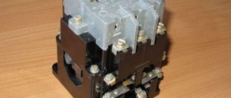
The design of the package electrical apparatus is simple and reliable. The batch switch consists of the following parts enclosed in the device body (see Fig. 1):
- a spring switching mechanism that provides an intermittent on/off process;
- fixed contacts arranged in a circle;
- movable contacts in the form of knives;
- package of spark arresting washers.
The terminals of the fixed group of contacts are located on the outside of the housing. Wires are connected to them. The moving contacts are located on a square insulating sleeve, which is driven by a spring mechanism that accumulates energy from the force applied to the handle.
Rice. 1. Batch device
The switch handle can have 4 positions. Two of them correspond to the “Enabled” position, and the other pair corresponds to the “Disabled” position.
Package switches are very similar in design to switches, but unlike them they have only one handle position in the off state. All other positions (there may be several of them) correspond to different switching methods.
The package terminals, connected to fixed contacts, are located on the switch body so that it is convenient to connect the wires. This is achieved in the following way: the contacts are shifted relative to each other, and the terminals from each contact are located diametrically opposite. Thus, the wires coming from the network are connected on one side, and the load on the other.
The industry supplies the market with single-pole, double-pole, three- and four-pole package switches. Their structure differs in the number of contacts in one contact group and, accordingly, in the number of spark arresting washers.
Figure 2 shows diagrams of different types of switches.
Rice. 2. Schemes of common packagers
There are open and closed type switches. Open package switches do not have a protective housing. Such devices are used for switching safe voltages and always indoors.
Protected closed-type bags are equipped with a plastic or aluminum housing. The devices are well protected from dust, and their terminals are covered from touching. They can be installed in rooms outside the switchboard.
Sealed models (see Fig. 3) are housed in sealed housings made of non-flammable, shockproof plastic. This protection class allows installation of devices even in open spaces.
Rice. 3. Appearance of a sealed bag
Principle of operation
The forces from the handle are transferred to the spring mechanism of the switch. The spring interacting with the figured washer starts up. At a certain moment, its energy is released, sharply turning the washer, dragging along the bushing with movable contacts. After making a quarter turn, the washer stops on one of the stops located on the top cover. Movable contacts, depending on the position of the handle, close or open contacts.
Due to the fact that the contacts are reinforced in fiber plates that evaporate when sparking, the arc is quickly extinguished by evaporation products. In addition, the fiber plates also act as guides, ensuring the precise trajectory of the contacts.
One- and two-pole package switches are designed for voltages of 220 V and loads from 10 to 25 A. Three-pole switches can withstand a potential difference of 380 V, but the current loads for them are reduced - to 6 or 15 A, depending on the model of the switch.
The service life of a batch switch depends on its operating conditions. The number of cycles is influenced by the parameters of rated currents and voltages. High-quality foreign switches operating in gentle modes reach a limit of 20,000 switchings, provided that the switching frequency is less than 300 operations per hour.
Main types and types of bags
Bags are classified according to different criteria:
- at the location where external electrical cables are connected to the panel (front, rear connection);
- according to the degree of protection of internal structural elements from negative environmental factors (open, protected, sealed devices are distinguished);
- according to the design features of the switches (packet-cam, drum).
Despite the wide variety of package switches and switches, they have common technical and operational characteristics and similar disadvantages.
Thus, the resource of the spring mechanism is designed for approximately 103 power outages. There are wear-resistant models that perform 203-1000 shutdowns. The main condition: the frequency of operation of the mechanism should not exceed 50 within 1 hour.
Image gallery
Photo from
Open package switch
Protected and unprotected packets
Bag in a sealed case
Modern fixed package switch
Product markings may include the following alphabetic and digital symbols:
- “B” – switch;
- “P” – switch;
- “P” – batch;
- “G” – sealed;
- numbers 1-4 – number of poles;
- “N” – direction (2, 3, 4, and also “R” – reverse).
The marking of devices indicates the degree of protection, type of placement, installation features, rated current. Sometimes you can find abbreviations “sil.” and "pl."
They are used to indicate the housing material (silumin, plastic). For example, the marking of the device GPPM-2-60/N2 stands for 2-pole 60-amp sealed packet switch for 2 directions.
Structural designation (labeling)
The generally accepted marking of package switches is carried out in the form of a structure: ПХ X XXX XX XX xxxx x. The inscription is deciphered as follows:
Table 1
| Item no. | structure | Decoding |
| 1 | PH | PV – packet switch; PP – packet switch |
| 2 | X | Number of poles: 1 – single-pole; 2 – bipolar; 3 – three-pole; 4 – four-pole. |
| 3 | XXX | Symbol for rated current parameters: 16 – 16 A; 40 – 40 A; 63 – 63 A; 100 – 100 A; 160 – 160 A. |
| 4 | XX | Number of directions (for switches) of electrical circuits: H2 – two directions; H3 – three directions; H4 – 4 directions; P – for motor reverse. |
| 5 | XX | Code of climatic modification and placement category according to GOST 16708-84 |
| 6 | xxxx | Code of degree of protection and case material: IP00 – open; IP30 – carbolite body; IP56 pl. – plastic; IP56 power – silumin. |
| 7 | x | Mounting method: 1 – front bracket, behind the 4 mm panel; 2 – front bracket behind the 25 mm panel; 3 – fastening with a rear bracket inside the cabinet; 4 – fastening to the body (for switches with degree of protection IP30, IP56). |
Batch switch
Until recently, switches and package switches were used to switch the electrical system manually.
Now this is all done automatically. The equipment is used based on the voltage supply power:
- 100 A – 220 V;
- 60 A – 380 V;
- 440 – 660 V.
The batch switch is a mechanism with a rotating device in the form of a lever. The device is produced in the form of a small container with a handle and terminal leads. The inside of the device is filled with contacts and switching mechanisms.
The body part itself consists of insulated washers connected by bolts. In old houses there are still samples produced in the USSR.
What to replace it with?
If the packet switch (switch) fails, it must be replaced with a new device of the same type with similar (or higher) parameters. To replace the switch, you can use a circuit breaker that is designed to operate with currents and rated voltages corresponding to the loads of a given circuit. Of course, the number of poles must be respected.
For orientation on the parameters, we provide a table with the parameters.
Table 2.
| Name | Number of poles | Rated current A | Number of switchings | Degree of protection | |
| 220V | 380V | ||||
| PV1-16-M3 | 1 | 16 | 10 | 1 | IP00 |
| PV2-16-M3 | 2 | 16 | 10 | 1 | IP00 |
| PV3-16-M3 | 3 | 16 | 10 | 1 | IP00 |
| PV2-40-M3 | 2 | 40 | 25 | 1 | IP00 |
| PV3-40-M3 | 3 | 40 | 25 | 1 | IP00 |
| PV4-40-M3 | 4 | 40 | 25 | 1 | IP00 |
| PV2-100-M3 | 2 | 100 | 60 | 1 | IP00 |
| PV3-100-M3 | 3 | 100 | 60 | 1 | IP00 |
| PV4-100-M3 | 4 | 100 | 60 | 1 | IP00 |
| PV1-16-M1 IP56 plastic | 1 | 16 | 10 | 1 | IP56 |
| PV2-16-M1 IP56 plastic | 2 | 16 | 10 | 1 | IP56 |
| PV3-16-M1 IP56 plastic | 3 | 16 | 10 | 1 | IP56 |
| PV2-40-M1 IP56 plastic | 2 | 40 | 25 | 1 | IP56 |
| PV3-40-M1 IP56 plastic | 3 | 40 | 25 | 1 | IP56 |
| PV4-40-M1 IP56 plastic | 4 | 40 | 25 | 1 | IP56 |
| PV2-100-M1 IP56 plastic | 2 | 100 | 60 | 1 | IP56 |
| PV3-100-M1 IP56 plastic | 3 | 100 | 60 | 1 | IP56 |
| PV4-100-M1 IP56 plastic | 4 | 100 | 60 | 1 | IP56 |
| PP1-16-H2-M3 | 1 | 16 | 10 | 2 | IP00 |
| PP2-16-H2-M3 | 2 | 16 | 10 | 2 | IP00 |
| PP3-16-H2-M3 | 3 | 16 | 10 | 2 | IP00 |
| PP4-16-H2-M3 | 4 | 16 | 10 | 2 | IP00 |
| PP2-40-H2-M3 | 2 | 40 | 25 | 2 | IP00 |
| PP3-40-H2-M3 | 3 | 40 | 25 | 2 | IP00 |
| PP4-40-H2-M3 | 4 | 40 | 25 | 2 | IP00 |
| PP2-100-H2-M3 | 2 | 100 | 60 | 2 | IP00 |
| PP3-100-H2-M3 | 3 | 100 | 60 | 2 | IP00 |
| PP4-100-H2-M3 | 4 | 100 | 60 | 2 | IP00 |
| PP2-16-H2-M2 IP56 plastic | 2 | 16 | 10 | 2 | IP56 |
| PP3-16-H2-M2 IP56 plastic | 3 | 16 | 10 | 2 | IP56 |
| PP4-16-H2-M2 IP56 plastic | 4 | 16 | 10 | 2 | IP56 |
| PP2-40-H2-M2 IP56 plastic | 2 | 40 | 25 | 2 | IP56 |
| PP3-40-H2-M2 IP56 plastic | 3 | 40 | 25 | 2 | IP56 |
| PP4-40-H2-M2 IP56 plastic | 4 | 40 | 25 | 2 | IP56 |
| PP2-100-H2-M2 IP56 plastic | 2 | 100 | 60 | 2 | IP56 |
| PP3-100-H2-M2 IP56 plastic | 3 | 100 | 60 | 2 | IP56 |
| PP3-16-H3-M3 | 3 | 16 | 10 | 3 | IP00 |
| PP3-40-H3-M3 | 3 | 40 | 25 | 3 | IP00 |
| PP4-40-H3-M3 | 4 | 40 | 25 | 3 | IP00 |
| PP2-100-H3-M3 | 2 | 100 | 60 | 3 | IP00 |
| PP3-100-H3-M3 | 3 | 100 | 60 | 3 | IP00 |
| PP4-100-H3-M3 | 4 | 100 | 60 | 3 | IP00 |
| PP2-16-H3-M2 IP56 plastic | 2 | 16 | 10 | 3 | IP56 |
| PP3-16-H3-M2 IP56 plastic | 3 | 16 | 10 | 3 | IP56 |
| PP4-16-H3-M2 IP56 plastic | 4 | 16 | 10 | 3 | IP56 |
| PP2-40-H3-M2 IP56 plastic | 2 | 40 | 25 | 3 | IP56 |
| PP3-40-H3-M2 IP56 plastic | 3 | 40 | 25 | 3 | IP56 |
| PP4-40-H3-M2 IP56 plastic | 4 | 40 | 25 | 3 | IP56 |
| PP2-100-H3-M2 IP56 plastic | 2 | 100 | 60 | 3 | IP56 |
| PP3-100-H3-M2 IP56 plastic | 3 | 100 | 60 | 3 | IP56 |
| PP1-16-H4-M3 | 1 | 16 | 10 | 4 | IP00 |
| PP2-16-H4-M3 | 2 | 16 | 10 | 4 | IP00 |
| PP3-16-H4-M3 | 3 | 16 | 10 | 4 | IP00 |
| PP4-16-H4-M3 | 4 | 16 | 10 | 4 | IP00 |
| PP2-40-H4-M3 | 2 | 40 | 25 | 4 | IP00 |
| PP3-40-H4-M3 | 3 | 40 | 25 | 4 | IP00 |
| PP4-40-H4-M3 | 4 | 40 | 25 | 4 | IP00 |
| PP2-100-H4-M3 | 2 | 100 | 60 | 4 | IP00 |
| PP3-100-H4-M3 | 3 | 100 | 60 | 4 | IP00 |
| PP4-100-H4-M3 | 4 | 100 | 60 | 4 | IP00 |
| PP2-16-H4-M2 IP56 plastic | 2 | 16 | 10 | 4 | IP56 |
| PP3-16-H4-M2 IP56 plastic | 3 | 16 | 10 | 4 | IP56 |
| PP4-16-H4-M2 IP56 plastic | 4 | 16 | 10 | 4 | IP56 |
| PP2-40-H4-M2 IP56 plastic | 2 | 40 | 25 | 4 | IP56 |
| PP3-40-H4-M2 IP56 plastic | 3 | 40 | 25 | 4 | IP56 |
| PP4-40-H4-M2 IP56 plastic | 4 | 40 | 25 | 4 | IP56 |
| PP2-100-H4-M2 IP56 plastic | 2 | 100 | 60 | 4 | IP56 |
| PP3-100-H4-M2 IP56 plastic | 3 | 100 | 60 | 4 | IP56 |
| PP3-16-P-M3 | 3 | 16 | 10 | Reversible | IP00 |
| PP3-40-P-M3 | 3 | 40 | 25 | Reversible | IP00 |
| PP3-100-P-M3 | 3 | 100 | 60 | Reversible | IP00 |
| PP3-16-P-M2 IP56 plastic | 3 | 16 | 10 | Reversible | IP56 |
| PP3-40-P-M2 IP56 plastic | 3 | 16 | 10 | Reversible | IP56 |
| PP3-100-P-M2 IP56 plastic | 3 | 100 | 60 | Reversible | IP56 |
Connection diagram
Packers were developed for use as input switches. Based on this, it is advisable to install them in front of the electric meter, so that if necessary, the entire apartment network can be disconnected. These devices do not protect electrical wiring and equipment from short circuits. For these purposes, circuit breakers are used.
Figure 4 shows an example of a wiring diagram in a one-room apartment, clearly demonstrating the principle of connecting a packet switch.
Rice. 4. Connecting a packet switch
Of course, instead of a batch switch, you can use an input circuit breaker, but this is not advisable. Firstly, it is expensive, secondly, such devices wear out quickly with frequent load outages, and thirdly, the machine may work if a short circuit appears in one of the circuits. Then the entire house or apartment will be left without electricity. The problem is solved by accurate calculations and adjustments of the settings of the input machine.
Phase switch device
It should be noted right away that the switch does not affect the quality of energy in any way; uninterruptible power supplies, generators, batteries, and the like are used for this purpose. The PF itself only selects from three phases the one that is most suitable for operation. The conclusion follows from this: the use of the switch is possible only if there are at least two phases. Where only one phase is connected, installing a PF will not change anything.
Switches can be divided into two groups:
- manual control;
- automatic control.
The electric switch is installed after the meter, so if there is a single-phase meter, it will have to be changed to a three-phase one. The power consumption does not change, the tariff remains the same, therefore, the costs of installing a new meter will be associated only with its cost and installation price, as well as with the supply of additional phases.
Using manual type
A three- or four-position cam toggle switch can be used as a manual type PF. The principle of operation of a manual phase switch is reduced to alternately switching on pairs of contacts.
They are available in two types:
- in the body;
- unframed.
The switch consists of a rotating rod on which one or more cams are located. There is a stopper to secure the position. Several pairs of contacts are used:
- movable;
- motionless.
To return to their original position, the moving contacts have a spring. The contacts themselves are usually coated with a layer of silver, which can withstand high temperatures. This is necessary so that when large currents are opened, the contacts do not burn out or fail.
The switch works as follows: when the shaft rotates, the cam closes one pair of contacts through the insulating rods. Further rotation causes the first pair to open and the second to close. Some designs have a position where all contacts are open. This position is called “off” and is designated “0”.
In other designs, the bar is moved not by a cam, but by a recess. The position at which one of the pairs of contacts is closed is designated by the number 1,2 and so on. As a rule, the switch shows a diagram of the contacts and the sequence of their closure.
Automatic control
Enterprises produce three-phase automatic phase switches in huge quantities. What should you pay attention to when purchasing? First of all, for switching current. This is the maximum current that this device is capable of breaking. After all, switching occurs without removing the load. What current is used in the room can be determined by the machines that are in front of the meter (if the meter has not been changed for a long time, then after it).
The second thing that will help you realize your preferences in setting is the display method. Based on this feature, devices can be divided into:
- LED;
- liquid crystal.
In the first case, the indication is made using LEDs; the color of the glow is different, but most often green. Installed at the input of each phase, thereby indicating which phase is currently in use. The liquid crystal display allows, among other things, to monitor the actual voltage.
An automatic three-phase switch works as follows: all connected current sources are under constant control, and the voltage value is measured. As soon as the readings of the main line go beyond the established values, the load is transferred to the reserve phase.
Monitoring of the main line continues, and after its readings return to normal, a reverse load transfer occurs. To switch the load, magnetic starters are used, they are also called phase switching relays.