Complex electrical circuits often contain several basic elements with different functions.
At the right moments they need to be switched between each other. To do this, electricians use a switching device called a cam switch. Its main application is to regulate engine parameters.
Let's take a closer look at the basic properties and design of the device. Let's also look at possible use cases.
What is it like?
In general, a cam switch is an electrical device that can be used with any type of current. Its main function is to switch control circuits of electrical devices.
As for the variability in the permissible voltage values, it is quite wide.
Thus, the device can operate both at relatively low values of 50 Volts and at significant loads of 500 Volts when using an alternating current network or 220 Volts for a direct type of electricity.
An important condition for the long service life and endurance of the circuit breaker is the quality of its construction materials.
The insulation layer and the conductors themselves are made of high quality raw materials. All stages of production are carried out using the latest technology. This ensures the small size of the device.
Also, thanks to the selected combination of materials, immunity to possible overloads is increased and a high level of switching capabilities is ensured.
In order to prevent problems associated with short circuits, a safety element is used.
Disadvantages of cam mechanisms
The most noticeable disadvantage is the complexity and high cost of producing mechanism parts. The most labor-intensive part is the production of the control profile. The technological process begins with the casting of a workpiece from high-strength steel alloys, which are particularly resistant to variable mechanical stress, abrasion and temperature changes. Next, high-precision machining is required, followed by grinding and polishing of the surfaces. Hardening of the working surface is achieved by heat treatment and carburization. Such camshafts or oil pump drive cams are expensive, but they can last hundreds of thousands of kilometers.
Another disadvantage is the small load that the pusher can push. This occurs due to the high friction in the mating pair, in addition, significant lateral loads arise on the rod. This drawback limits the power capabilities of the device's executive body.
To combat this drawback, a roller pusher is used, placed on a ball or needle bearing. For large engines with large valve diameters and powerful return springs, a rocker arm design is used. The different lengths of the rocker arms work like a lever system, transforming more travel on one arm into more force on the other.
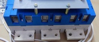
Design Features
The basic principle of the device comes from the name itself. So, all the work happens thanks to the presence of so-called “cams” that act on the pusher.
If you delve deeper into the design itself, you can see that the switch consists of a whole group of switching elements.
By influencing each of them in a certain way, the operation changes and the switching scheme is selected. For each subtype of cam switches, its own switching program is used.
It determines the initial and subsequent positions of the cams and main contacts. The entire structure and conductors are in a plastic sheath. The material from which it is made is melamine.
A shell of this type protects the filling from the influence of electric arcs and eddy currents. Thanks to the mechanical connection of the cams to each other, it is possible to simultaneously switch off several contacts.
When it comes to the materials the conductors are made from, most switches use silver. This raw material prevails over copper in most of the necessary parameters.
Due to their ability to withstand electric arcs, silver conductors guarantee high-quality switching and long service life.
For high-quality switching, it is also necessary to fix the cams in a given position. The reliability of this is guaranteed by the drive locking mechanisms. There are several limit positions for the switch handle itself.
To ensure clear switching between them, a motion limiter is used in the design. The drive itself has the form of a rod with a square cross section.
To ensure high-quality work under permissible loads, it is made of metal. This point is especially important when switching an electric motor. There is a shift handle on the outside of the housing. It must have reliable insulation.
Switch operating principle
As mentioned above, a cam switch works by switching, using a handle, to a specific group of contacts of the device. So, during one revolution of the handle, the internal drive rotates around the axis.
As a result, it drives several cams. Next, the action and subsequent closure of a certain group of contacts occurs, which corresponds to the selected switch position.
The operating principle and contact closure are described in more detail for each switch separately and this information is contained in its connection diagram. Next, when the switch takes the intended position, the locking mechanism comes into operation.
Only after this the operation of the electrical device itself begins. In the same way, you can return the switch to its original position. There are models on the market with automatic or mechanical turning of the handle.
How to connect
Let's give an example of implementing a lighting control scheme from two places using Legrand switches. This manufacturer produces reliable household models of the Cariva and Valena series, the price of which is not much different from the cost of conventional switches.
Before you buy switches, pay attention to the various designs; they can be for both hidden and open wiring, as well as with backlighting and position indication on the box (case).
We remind you that all work related to connecting electrical equipment must be performed only when the electrical circuits are completely de-energized. Therefore, before proceeding, make sure that the electricity is turned off; it is advisable to use a special device (probe) for this.
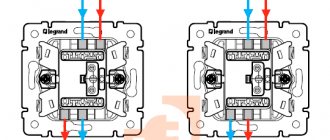
A schematic implementation of the task is shown in the figure below.
Schematic illustration of a dual lighting control installation
The neutral wire is blue, the phase is red. Note that all switching must be performed with the phase.
How a single-key switch is connected can be seen in the bottom figure.
Installation diagram of two Legrand single-key switches
Connecting switches for management from three places is as follows.
Connection to control lighting from three different locations
As you can see, it’s not difficult to connect a one-key or two-key two-way switch, and it will help make lighting control in your apartment more comfortable.
Main purpose
Cam switches have a clear purpose. Let's take a closer look at all the possible options.
- Management of electrical mechanisms, the main work of which is based on motors. Moreover, the latter can have one or three phases. In this case, the switch can change the direction of torsion or the type of connection of the windings.
- In operational type circuits, the cam switch performs the role of control and signaling.
- If the switch is connected to the welding machine, it performs several roles, including turning on and off, as well as switching positions.
- In the resistance group it provides the necessary connection.
- In heating equipment it is used to switch and control the heating order.
- In large substations with transformers, it is used to regulate the operation of the sectional disconnector drive.
Types of household switching devices
Switches come in push-button, key and rotary types. The first option is usually used only as a bell at the front door. It is not suitable for lighting control.
But the second type for turning on/off lights in a residential building is just what you need. The rotating version is more intended for production and utility rooms. Such products do not have a very presentable appearance.
Depending on the number of keys, switches are:
- single-key;
- two-key;
- three-key.
They are divided into regular (pass), combined and cross (intermediate). The first ones have three contacts. For the latter, this three terminals is increased by multiplying by the number of keys. And the third has two entrances and exits. The latter are intended for circuits with not two, but several light switching points.
By type of control in private homes, light switches are usually standard keypads, but there are also models with sensors and remote control
According to the wiring diagram, switches are available for open (overhead products) and hidden (built-in analogues) wiring. The first ones are fastened to the wall with self-tapping dowels, and the second ones are fixed in the socket boxes with the help of expanding legs.
When choosing switches for connection according to the pass-through switch circuit, it is necessary to correctly select the number of keys (one for each connected group). If you plan to make two control points, then you will only need a pair of ordinary three-pin devices.
If more of these points are needed, then for each such place you will have to additionally take an intermediate crossover device to be included in a single system.
In the vast majority of cases, the key of a household switch has two positions for closing one of the circuits. But there are also modifications with a zero middle state. In this situation, both circuits are broken.
Main Applications
The need to switch and adjust the operating modes of electrical devices arises both in households and in large enterprises.
This provokes the widespread use of the cam switch. This type of switch is also often used at power supply substations and on water types of transport.
Thus, a cam switch is a fairly small device with a lot of capabilities. High-quality assembly and materials guarantee a long service life.