Electricity is supplied to consumers over considerable distances. In this case, a certain voltage level is used, the value of which is brought to normal due to the operation of a TMG type power transformer. The technical decoding of the device indicates the type of device: T - three phases, M - oil and air cooling, G - tightness. In other words, TMG is a power three-phase oil sealed transformer for equalizing voltage in alternating current networks.
Transformer TMG
Principle of operation
TMG power plants are irreplaceable and reliable devices. The principle of operation of the units is to bring the voltage value to an acceptable value in the process of induction of an alternating current electromagnetic field (leveling), avoiding surges and instability. This is achieved thanks to its design and technical characteristics.
Transformer operating principle
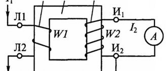
A transformer is a static device that converts current and voltage through mutual induction. Layer windings of primary and secondary voltage are initially placed on a frame made of electrical steel. When the secondary winding opens, the primary winding receives voltage and creates a magnetic field with a flux that closes along the core. The magnetic flux meshes with the turns of the windings, due to which the electromotive force is brought back to normal, and the voltage in the network is 220 V.
In this case, the recommended winding connection is star. No-load losses are 15%, and the rated voltage reaches 0.4-0.35 kV. During operation, the unit is cooled by oil located in a sealed tank, the temperature of which is automatically regulated, preventing overheating.
Winding connection diagrams
Section: Transformers / Date: August 22, 2022 at 12:06 / In accordance with GOST, power transformers 10(6)/0.4 kV with a power from 25 to 2500 kVA can be manufactured with the following winding connection diagrams :
“star/star” - Y/Yн-0 ; “triangle-star” - D/Yн-11; “zigzag star” - Y/Zн-11. The fundamental difference in the technical characteristics of transformers with different winding connection diagrams is the different response to asymmetrical currents containing a zero-sequence component. These are primarily single-phase through short circuits, as well as operating modes with uneven phase loading. As is known, 6(10)/0.4 kV power transformers have a three-rod steel core, on each rod of which there are primary and secondary windings of the corresponding phase - A, B and C. The magnetic fluxes of the three phases in symmetrical operating modes circulate in the steel core of the transformer and do not go beyond it. What happens when symmetry is broken with a predominance of the load of one of the phases on the 0.4 kV side? Such modes of operation are studied using the theory of symmetrical components. According to this theory, any asymmetrical mode of operation of a three-phase network is represented as a geometric sum of three symmetrical components of current and voltage: these are the direct, negative and zero sequence components.
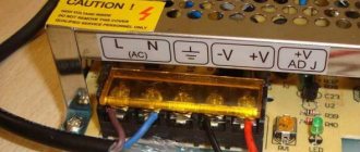
* U/UN-0: the HV winding is connected in a star, the LV winding is connected in a star with the neutral brought out; group 0;
* D/UN-11 : the HV winding is connected in a triangle, the LV winding is connected in a star with the neutral brought out; group 11;
* U/ZN-11: the HV winding is connected in a star, the LV winding is connected in a zigzag with the neutral brought out; group 11.
For transformers (from 25 to 250 kVA), protected by fuses on the HV side, the winding connection diagram Y/Zн-11 . Y/Yn-0 scheme gives a slightly smaller effect . D/Yn-11 circuit should not be used for such transformers. The connection diagram for the windings of transformers D/Yn-11 can be used in relatively rare cases for more powerful transformers when it is necessary to limit the single-phase short-circuit current in order to increase the stability of switching equipment. Manufacturers of power transformers should necessarily measure their zero-sequence resistance.
- We recommend
- Comments
What is a transformer revision?
Read more
Characteristics of TM transformers
Read more
Commercial accounting point (PKU-10)
Read more
- admin (Author)
October 5, 2022 at 9:51 am · Reply
Click to cancel reply.
Design
The TMG case is durable and sealed, withstanding long-distance transportation. The unit is small in size, has a reliable sealed housing to protect the magnetic circuit and a durable mechanism. The unit is capable of operating under temperature fluctuations from +40 to -60 degrees. In this case, a non-explosive environment and protection from dust must be ensured.
Also read: What is a transformer
The design consists of the following components:
- Core made of special steel.
- Insulated metal winding, with high and low voltage inputs, magnetic circuit and high voltage switch.
- Coil with rated voltage.
- Corrugated sealed closed tank, with an oil filling level from 470 to 1570 ml and an oil level indicator.
- Thermometer for monitoring oil layer temperature.
- Safety valve and switch without excitation.
- Air dryer with expansion.
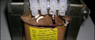
There is also a ground plate and drain plug at the bottom of the oil tank. The technical parameters of the TMG are indicated by the manufacturer on the outside of the unit in the form of a plate.
The net weight of the transformer is 280-920 kg, and with oil - 320-980 kg. The average dimensions of the unit are 1000x500mm.
Classification
TMG is divided into the following main types:
- Regarding appointments:
- intermediate
- measuring;
- protective;
- laboratory
- According to the installation method:
- external;
- internal;
- portable;
- stationary;
- tire;
- supporting
- By number of steps:
- single stage;
- cascading.
- By voltage rating:
- high voltage;
- low voltage.
- For winding insulation:
- dry;
- paper-oil;
- compound.
The power transformer is measured in kW units, and is used as a transformer substation kit.
Specifications
TMG power oil transformers are characterized by stable operation and high power. All this is achieved thanks to the technical indicators of the unit with GOST - 11677-85.
Technical characteristics of the TMG type transformer (to enlarge the table, click on it)
Table with characteristics for the TMG-1600 transformer
More detailed characteristics and dimensions can be found in the file: Open file
Transformer TMG 12
Three-phase oil transformers (TMG 12) of hermetically sealed design without oil conservators are designed for converting electricity in the networks of power systems and electricity consumers. The level of no-load and short-circuit losses in this series of transformers complies with CENELEC recommendations. The neutral input of the LV side of the transformer is designed for continuous load with a current equal to 100% of the rated current of the LV winding. The difference between these transformers and the previous ones is that, along with a significant reduction in the level of losses, the noise characteristics are improved. In terms of noise level, they are better than special low-noise transformers TMGMSH.
You can get more detailed information by downloading the PDF file
Description pdf, 1.11 MB
Order
I'll order later
{catalog::form[transformers](transformator-tmg-12)} Top
Device price
The cost of the unit depends on the type, area of its purpose and dimensions. Household transformers in the Russian Federation can be purchased from 14,000 to 21,000 rubles - the price depends on the region. For example, production amounts in 2022 in rubles:
- TMG-25 11 – 69 500;
- TMG-40 11 – 78 500;
- TMG-100 11 – 103 700;
- TMG-1000 11 – 413,500.
Also read: Single-phase dry transformer - OSM
It is best to purchase devices from domestic manufacturers. At the moment they are the best.
Marking
The alphanumeric designation of a transformer characterizes its quality characteristics, voltage class and power. There are different types of markings.
All TMG symbols are divided by 1/2/3/4.5, where:
- Amount of power.
- Nominal HV.
- Nominal NN.
- Climatic version, category according to GOST.
Decoding the TMG transformer markings
Explanation and symbol
Explanation of the TMG type transformer: T – three-phase, M – oil and air cooling, G – hermetically sealed design.
Symbols for the TMG transformer – 1/2/3-4.5, where:
- Amount of power.
- The value of the nominal HV.
- The value of the nominal LV.
- Climatic design, placement category according to GOST.
- Connection of the windings of the device (information is displayed about which circuit and into which group the windings were connected).
As an example, consider the transformer TMGSU - 40 /6(10)/0.4 - U1, U/U. In deciphering a transformer, type means the presence of a balun. The power of this device is 40 kVA. HV voltage – 6 (10) kV, LV voltage – 0.4 kV, use in a temperate macroclimatic region, outdoors exposed to any atmospheric factors, U/U type connection.
TMG parameters:
- Rated current value: 0.4-0.35 kV.
- Idling losses: parameter value within -15%..
- Recommended connection: star.
- Weight: 280-920 kilograms, weight with oil: 320-980 kilograms.
- Level of filling/topping up oil into the transformer: 470-1570 millimeters.
- Average dimensions: 1000x500mm.
Detailed characteristics of TMG are presented in the table:
| Type | Power, kVA | Rated HV, kV | Rated LV, kV | Connection diagram and group |
| TMG-16 | 16 | 6,10 | 400 | U/Un-0 |
| TMG-25 | 25 | 6,10 | 400 | U/Un-0 |
| TMG-32 | 32 | 6,10,20 | 400 | U/Un-0 |
| TMG-40 | 40 | 6,10,20 | 400 | U/Un-0 |
| TMG-63 | 63 | 6,10 | 400 | U/Un-0 |
| TMG-100 | 100 | 6,10 | 0,4 | U/Un-0 |
| TMG-160 | 160 | 6,10 | 0,4 | U/Un-0 |
| TMG-250 | 250 | 6,10 | 0,4 | U/Un-0 D/Un-11 |
| TMG-400 | 400 | 6,10 | 0,4 | U/Un-0 D/Un-11 |
| TMG-630 | 630 | 6,10 | 0,4 | D/Un-11 U/Un-0 |
| TMG-800 | 800 | 6,10,20 | 400 | U/Un-0 |
| TMG-1000 | 1000 | 6,10 | 0,4/6,3/10,5 | D/Un-11 U/Un-0 U/D-11 |
| TMG-1250 | 1250 | 6,10,20 | 400 | U/Un-0 |
| TMG-1600 | 1600 | 6,10,20 | 400 | U/Un-0 |
| TMG-2500 | 2500 | 6,10,20 | 400 | U/Un-0 |
Purpose and scope
TMGs are used in various conditions, but the purpose depends on the placement category, determined by the parameters: 2, 3, 4 and the installation altitude above sea level, which should not be higher than 1000 m.
Units with a power from 1000 to 2500 kVA, with pressure gauge signaling thermometers, are intended for use under a canopy and indoors at temperatures from -40 to +60 degrees.
The devices cannot be used in conditions of strong vibration, possible mechanical shock, chemically active or explosive environments. It is recommended to install dry transformers or devices with built-in protection relays near flammable objects, as well as in hot climates.
Experienced craftsmen for production needs advise using models like SESH, which equalize the voltage and at the same time save energy.
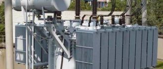
Transformer TMG
TMG transformers (three-phase oil sealed) are used to convert electricity in power supply networks and electricity consumers in outdoor or indoor conditions in a moderate (from + 40°C to minus 45°C) or cold (from + 40°C to minus 60°C) climate.
The environment is non-explosive and does not contain dust in concentrations that reduce the parameters of products within unacceptable limits. Transformers are not designed to operate in conditions of shaking, vibration, shock, or in a chemically active environment. The height of the TMG installation above sea level is no more than 1000 m.
Nominal frequency 50 Hz. Voltage regulation in the TMG is carried out in the range of up to ± 5% on a completely disconnected transformer (PBV) by switching the branches of the HV winding in steps of 2.5%.
Transformers are sealed, without oil conservators. Temperature changes in oil volume are compensated by changes in the volume of the tank corrugations due to their plastic deformation.
To monitor the oil level, transformers are equipped with a float-type oil indicator.
To compensate for excess pressure in the tank above the permissible limit, a safety valve is installed in transformers with a power from 16 to 63 kVA. To monitor the internal pressure in the tank and alarm if it exceeds the permissible values in transformers with a power of 100 kVA and higher, located in the room, it is provided (upon customer request) the installation of an electric contact pressure-vacuum gauge.
To measure the temperature of the upper layers of oil, a sleeve is provided on the transformer cover for installing a thermometer.
To measure the temperature of the upper layers of oil and control external electrical circuits, a 1000 kVA transformer (upon customer request) is equipped with a pressure gauge signaling thermometer.
TMG transformers with a power of 160 kVA and higher (upon customer request) are equipped with rollers for moving the transformer.
You can get more detailed information by downloading the PDF file
Description pdf, 517.15 KB
Order
I'll order later
Top
Requirements for operation
To use and inspect the unit for the purpose of maintenance, it is necessary to strictly observe safety precautions in protective work clothing, a mask, and dielectric gloves. The indoor transformer must be installed in a dry room with a floor-mounted type, and at the beginning of operation the TMG frequency must be 50 Hz.
Do not start the device if you know about its external damage in the form of holes and dents. When checking equipment, the power supply in the networks is temporarily interrupted. Before use, check the oil level to ensure there is no leakage. It is also necessary to check the operation of the voltage switch. Adjustment is possible in the range – ± 5%.
Also read: What is an autotransformer (LATR)
Maintenance and checking the operation of the device must be carried out with the device turned off.
User manual
Installation and commissioning of the TMG must be carried out by a specialist, in accordance with strict adherence to safety rules, instructions and “Regulations for the technical operation of power plants and electrical networks”:
- It is forbidden to work with the device without grounding, with a broken clamp and without proper repair.
- You cannot start a transformer that does not meet the required coolant oil level.
- Before adding oil, you must make sure that it meets the declared parameters and characteristics of the manufacturer, and has a quality certificate.
- Do not use oil that has been used for other purposes.
- Oil is topped up if necessary, with a breakdown voltage within 35 kV.
- If possible, it is advisable to check the operation of the floor-standing unit daily.
- TMG must be connected to the network with the specified current frequency.
- All acceptable forms of vibration must be eliminated.
- It is necessary to strictly observe the connection in accordance with the switching and starting diagram, after an external audit.
- It is also necessary to ensure the required microclimate in the room and exclude direct exposure to sunlight.
Transformer TMG 11
Three-phase oil transformers of the 11th series of hermetically sealed design without oil conservators are designed for converting electricity in the networks of power systems and electricity consumers. The neutral input of the LV side of the transformer is designed for continuous load with a current equal to 100% of the rated current of the LV winding. Their main difference from the TMG transformers is that the TMG11 has much lower no-load losses, while maintaining compact dimensions.
You can get more detailed information by downloading the PDF file
Description pdf, 165.43 KB
Order
I'll order later
{catalog::form[transformers](transformator-tmg-11)} Top