More often, motor reversal is performed with one reversing magnetic starter.
In multi-motor drives or drives of mechanisms connected by a common technological dependence, a certain sequence of turning on and off electric motors must be ensured. The engine stops. Interlocks are also used when installing barriers in hazardous areas of equipment. The magnetic starter circuit includes a contact belonging to the contactor that controls the motor. Irreversible magnetic starter circuit
Triggered closing contacts of the dynamic braking relay K3. If the engine stops, the engine switches off automatically. If the pressure in the compressor lubrication system drops, the RDM contact will close, a closed alarm circuit will be created and the bell will sound (not shown in the diagram). At the same time, block contact L1 opens and de-energizes relay RU1. It is possible to control an asynchronous motor from a larger number of places. Figure 5 - Scheme for controlling an electric motor from two places if there is an appropriate number of push-button stations. Figure 6 - Scheme for controlling an asynchronous motor using a reversible magnetic starter: a - power circuit; b - control circuit with electrical interlocking by contacts of the magnetic starter and contacts of the push-button station; c - control circuit with electrical blocking by contacts of the magnetic starter. Reversible magnetic starters are equipped with two non-reversible ones.
The auxiliary contact KM in the control circuit bypasses the SBC push-button switch and ensures continuous operation of the drive after the pressing load is removed from the push-button switch. Scheme of non-reversible control of a three-phase asynchronous motor with a squirrel-cage rotor during dynamic braking. In drives that use squirrel-cage motors, the rotational speed of the electric motor is changed by changing the number of pole pairs. The electric motor has a high starting torque and does not allow direct starting.
Two-wire arrow control circuit
Electric drive control circuits
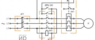
Scheme for starting an asynchronous motor with a wound rotor using a magnetic station P. When the three-pole switch Q1, made in the form of a switch, is switched on, pressing the start button S2 leads to the connection of the coil of the linear contactor K1 to the power source and switching on by the main closing contacts K1. The circuit provides direct starting and reversing of the engine, as well as back-on braking during manual non-automatic control.
When the temperature drops to the set temperature, the DOT opens and the compressor turns off. Scheme of sequential connection of motors Example 5.
Rheostatic starting of an asynchronous motor with a short-circuit rotor. Point P is the starting point. One asynchronous low-voltage electric motor designed to drive the compressor.
Motor protection for reverse control is the same as for non-reversible control. When reversing the engine while moving, it first decelerates from a given speed to zero, and then accelerates in the other direction.
If it is only necessary to brake the engine when it reaches zero rotation speed, the SВЗ button must be pressed again, which will lead to disconnecting the engine from the network and returning the circuit to its original position. Means for inhalation anesthesia: Anesthesia occurs as a result of inhalation of drugs, which is carried out or using a mask. It is enough to apply three-phase voltage to the engine stator and the engine starts immediately. The rotational speed of an asynchronous motor can be adjusted by changing the frequency of the supply network current, the number of pole pairs of the stator winding, and introducing a resistance into the rotor circuit, which causes an increase in slip. Magnetic starter control circuits
Electric drive - AC or DC?
The annual sales growth rate for variable speed drives is approximately 6%, while the growth rate for AC drives is 8%, and the market size for DC drives remains more or less stable. This article is intended for end users, OEMs, system integrators, and other drive engineers to outline the benefits of choosing one of the two main types of variable speed drive, DC or AC, for a variety of applications.
Which drive solution should you choose - DC or AC?
Power static converters
Microprocessor-based drives used in both AC and DC drives have now reached a very high technical level, which (within acceptable technological limits) allows the use of an
AC drive
where
a DC drive
. However, the traditional DC drive (1-quadrant and 4-quadrant) continues to play an important role, especially in applications where it is necessary to provide highly dynamic modes with constant torque, stringent overload requirements over a wide speed range and energy recovery back to net.
Main selection criteria
The first thing a user must do is to objectively evaluate the options available on the variable speed drive market that technically meet the application/process requirements. The main criteria for this assessment should be: 1. The total cost of purchasing the variable speed drive and the required additional equipment 2. Ongoing operating costs:
- service;
- production costs, efficiency, etc.;
- required placement area.
3. Technological and innovative aspects:
- dynamic response, acceleration time; 4-quadrant operations; emergency stop, etc.
- weight and dimensions characteristics.
4. Operational reliability, suitability of drives:
- compliance with international requirements and standards IEC, GOST R, EN, CE-EMC; CSA, UL, etc.;
- environmental conditions; degree of housing protection; on-site repairs
5. Impact on the external environment:
- mains voltage distortion
- EMC
6. Space requirement for inverter and motor 7. Heat dissipation
Comparison of the main characteristics of DC and AC drives in industrial applications
A comparison is made between 6-pulse 3-phase independently excited DC thyristor drives [hereinafter referred to as SDC
] and 3-phase AC electric drives based on a frequency converter with pulse-width modulation and an asynchronous motor [hereinafter referred to as
VFD
- variable frequency drive], in the following typical categories: PPT - P = 11 kW ... 5200 kW; U = 200 V … 1190 V VFD – P = 0.75 kW … 2000 kW; U = 380 V … 690 V
DC drive
Variable Frequency Drive
To a first approximation, there are not many significant differences between these drives; however, upon closer examination, the characteristic features of the drives and the difference in the physical principles of operation are revealed. Further in the article, aspects of the differences between drives are revealed on the following points:
- characteristics of motors as electromechanical converters
- characteristics of electrical energy converters
- 4-quadrant drives
- impact on the external environment
- modernization of DC drives
Differences between DC and AC motors
Most users have the following general understanding of electric motors: “DC motors
complex, requiring frequent maintenance, which makes their operation expensive; In addition, they have a low degree of protection. AC motors (asynchronous motors) are simple and reliable, do not require maintenance, have a lower price, and also have a higher degree of protection.” This classification may be true for many simple applications; Nevertheless, it is advisable to subject this general verdict to more careful consideration!
Mechanical characteristics of DC drives
The commonly used independent ventilation (in approximately 85% of variable speed drives up to 250 kW) guarantees good heat dissipation from the DC motor rotor over the entire speed range.
Typical applications requiring constant torque over a wide speed range: wire drawing mills, reciprocating compressors, hoists, ropeways, extruders, ...
Mechanical characteristics of variable frequency drives
The commonly used self-ventilation (approx. 90% of variable speed drives up to 250 kW) in standard asynchronous motors is not effective over the entire speed range. At low speeds, heat removal is virtually impossible.
Typical applications with reduced torque at low speed, corresponding to the characteristic in Fig. 4: pumps, fans, etc. with a quadratic dependence of load on speed...
Characteristics of the power-speed ratio in S1 mode of DC and AC motors:
(1) Unlike a standard induction motor with a fixed base (nominal) speed (synchronous speeds of 3000/1500/1000/… rpm at 50 Hz), a DC motor can be designed with a base speed ranging from approximately 300 up to 4000 rpm for each operating point. (2) Depending on the size, DC motors (both compensated and uncompensated) can have a field weakening range of 1:3 or 1:5. (3) The power limitation is related to the maximum torque of the asynchronous motor, which decreases inversely to the square of the speed (1/n2). (4) Power limitation is due to the reduction in switching capacity of the brushed DC motor
.
Comparison of motor performance shows that a DC motor is superior to an induction motor for continuous operation at low speeds and for a wide range of speeds at constant power. The short-term overload capacity depends not only on the motor parameters, but to a large extent on the characteristics of the frequency converter / thyristor converter. The wider the speed range over which a motor can produce maximum power, the better it can be adapted to processes that require constant torque throughout the entire speed range. Typical application: winding devices.
• Sizes, moments of inertia and acceleration times:
The main technical differences between
DC and AC
, methods of generating magnetic flux and dissipation of power losses also cause different dimensions (height of the shaft rotation axis H) and rotor moment of inertia (Jrotor), with the same rated motor torque.
DC
motors have a significantly lower axis height
H
and rotor mass than asynchronous motors, and therefore have a lower rotor moment of inertia Jrotor, which is a significant advantage in highly dynamic applications such as test benches, flying shears, and reversible drives, since this affects the acceleration time and dynamic response of the motor in 4-quadrant applications (motoring and braking).
• Wide speed range at constant power (field weakening operation or excitation control range):
Specialized drive applications such as winder/unwinder drive, test bench, winch, etc. require a very wide speed range at constant power.
In this case, the traditional field weakening operating mode of a separately excited
is particularly cost-effective. This means: a wide speed range at which the engine can produce maximum power (the length of the horizontal characteristic line in Fig. 5 from nG to n1), a smaller engine power reserve Pmax(motor) / Pmax(load) is required.
• Engine maintenance:
Currently, depending on the complexity of the application,
DC motor
is approximately 7000...12000 hours, thanks to a modern commutator assembly, carbon brushes and an optimized excitation field. Depending on the mechanical operating conditions, the lubricant replacement interval in DC/AC motors can be comparable, and often less, than the life of the brushes of a commutator motor.
• Engine protection degree:
Historically, since the 20s,
DC motors
have been developed mainly for variable speed drives, which led to the use of internal forced independent ventilation (in approximately 85% of motors up to 250 kW). Standard asynchronous motors began to be used actively in the 70s/80s and were mostly (approx. 90% up to 250 kW) manufactured with surface self-ventilation, since variable frequency drives were not widespread at that time. In fact, all asynchronous motors with a power of approx. up to 1400 kW have a degree of protection IP 54 as standard, thanks to their simple and robust design. For operation in hazardous areas, explosion-proof asynchronous motors are almost exclusively used. The asynchronous motor has won a leading position for itself and has proven its effectiveness in those industrial sectors that are characterized by aggressive environmental conditions, high levels of pollution and dust.
• Weight and location for engine installation:
The lower weight and dimensions
of DC motors
(standard protection
IP 23
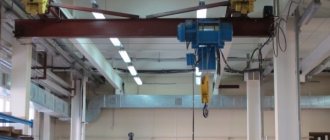
) compared to asynchronous motors (standard protection IP 54) are especially important for applications where the motor must be moved along with the load (e.g. large cranes, overhead cranes) , or in systems where compact placement is important (drilling rigs, ski lifts, marine applications, printing machines, etc.).
Differences between Thyristor DC Converters and Frequency Converters
• Switching and conversion of electrical energy:
Block diagram of a 1-quadrant DC drive
The transition of current from one thyristor to another begins with a starting pulse, and after that continues in a linearly interconnected mode. This means that the voltage between the switched phases of the network is polarized in such a way that the current of the newly opened thyristor increases, and turns off the previous thyristor, reducing its current to zero. The thyristors are switched naturally (by mains voltage) when the current passes through zero, and the thyristors are switched off without any problems even with significant overload. Therefore, thyristors can be selected not by peak current, but by the average rated load current.
Block diagram of the frequency converter
Although the input bridge rectifier of a frequency converter works like a DC drive, the current rectified by it must be converted back to 3-phase AC using an inverter. Since direct current does not have any zero crossings, switching elements ( IGBT transistors)
) must interrupt the full load current. When the IGBT turns off, current flows through the freewheeling diode to the opposite pole of the DC voltage. Switching occurs without voltage control, but is possible at any time, regardless of the shape of the mains voltage.
Result:
Switching in frequency converters occurs at high frequencies and a high-frequency component appears in the output voltage, and problems with electromagnetic compatibility may arise. In DC-DC converters there is only one power conversion circuit (AC → DC). Frequency converters have two energy conversion circuits (AC → DC and DC → AC), i.e. Power losses are doubled compared to DC drives. The power losses obtained empirically are as follows: PPT - 0.8% ... 1.5% of the rated power; VFD - 2% ... 3.5% of rated power. Space required to place a converter cabinet with a power of 100 kW or more: PPT - 100%, VFD - 130% ... 300%. This advantage of DC drives results in a reduction in the size and cost of the control cabinet and cooling system.
• Output currents of AC and DC converters; engine noise; winding insulation load, electromagnetic compatibility (EMC):
PPT
• Motor Current/Noise: The voltage supplied to the motor consists of segments from the sinusoidal mains voltage. The motor current is DC with a superimposed AC component from the bridge rectifier, so noise emissions are not an issue in a DC drive.
• Motor torque ripple: The pulsating torque (foscill = 6 x fline = 300 Hz or 360 Hz), resulting from current ripple, is superimposed on the fundamental torque and is significantly higher in frequency than the mechanical resonant frequencies. For this reason, there will be no problem for applications such as winders/unwinders, etc.
• Motor voltage/winding insulation: The maximum voltage that is applied to the DC motor terminals is equivalent to the peak line voltage (UN • √2 ).
• EMC: For the reasons mentioned above, the installation costs required to reduce electromagnetic emissions (to meet EMC requirements) are relatively small in DC drives.
VFD
• Motor Current/Noise: Noise emission in variable frequency drives is highly dependent on the selected clock frequency in each application.
• Relative harmonic components in the motor torque: The pulsating torque resulting from the harmonic components of current and voltage (deviation from ideal sine) in amplitude and frequency is very dependent on the operating point and operating principle of the frequency converter. The likelihood of induced vibrations in the drive system (engine, clutch, transmission, mechanical components, etc.) is correspondingly greater.
• Motor voltage/winding insulation: The output signal of the IGBT PWM inverter contains steep voltage edges, which in the case of a long motor cable (> 10 m) can lead to 2-fold peak overvoltages at the motor. As a result, the impact on the insulation of the motor windings increases, which can lead to its aging and breakdown. This situation can be corrected by using a motor with a higher insulation class, or by installing a choke at the output of the frequency converter.
• EMC: Electromagnetic emissions in variable frequency drives, especially those associated with long cable runs, may require additional measures and equipment.
• Impact on mains voltage:
Linear currents of DC drives with
a 6-pulse thyristor bridge
will always contain, in addition to the main harmonic, the 5th, 7th, 11th and 13th harmonics in the corresponding percentages: 22%, 14%, 9%, 7.6% .
In case of operation of several DC drives connected to the same mains voltage source, they will slightly balance each other due to different phase sequences, and the overall mains voltage distortion will be reduced. In frequency converters, switching IGBT transistors
practically does not create
low-frequency
harmonic distortions, but
high-frequency
components are significant.
• Reactive power:
Both types of drives
(PPT and NPP)
consume reactive power from the network. Its size is not significant in variable-frequency drives, but in DC drives it is more significant and depends on the engine speed. Frequency drives have preference in this matter.
Empirical values for DC drives: 1-quadrant applications - cos ≈ 0...0.9 4-quadrant applications - cos ≈ 0...0.85
Empirical values for variable frequency drives: 1-Q applications (with diode input bridge) - cos ≈ 0.99 4-Q applications (with thyristor input bridge and regeneration to the network) - cos ≈ 0.9
Modernization of existing DC drives.
When the question arises about whether it is worth upgrading an existing DC drive or whether it is cheaper to completely replace it with an AC drive, you need to approach this issue carefully and consider all the arguments, both pros and cons.
There are basically several upgrade levels available:
- Complete replacement of the DC drive (converter and motor) with a new modern DC drive.
- Replace only the converter if the engine is in good condition.
- Replacing one of the converter modules with a new one.
- Replacing analogue control electronics with digital ones without changing the power section (recommended only for powers above 1 MW).
- Complete replacement of the entire drive system with a variable frequency drive.
When answering the question of which approach to choose in each specific case, it is important to evaluate a number of criteria:
- Could there be a need to change the drive in the future (change in the type or nature of the load, operating conditions, etc.)?
- What is the condition of the individual system components (reliability, age, operating costs)?
- Before deciding to replace the DC drive with a VFD
, consider the following points:
- Costs for laying new cables.
- Place for placing the frequency converter.
- Will switching equipment need to be replaced?
- Possibility and complexity of mechanical installation of a new engine
- Duration of all drive replacement work./
Price comparison of DC and AC drive systems
(drive + motor or complete control + motor cabinet) Based on today's prices for DC and AC drives, taking into account the above advantages and disadvantages of various solutions, the following assessment can be used as a guide: 1-Q drives < 40...80 kW → VFDs are less expensive 4-quadrant drives < 40…60 kW (Frequency converter + braking (module) resistor); → PDC less expensive Regenerative 4-Q drives > 15 kW → PDC less expensive
Conclusion
The main disadvantage of analog DC drive
is low noise immunity, difficulty in setting up and instability of parameters. A tachogenerator is used as a speed feedback sensor, which has the same disadvantages as a commutator motor. For reversible drives, a diode bridge must be installed after the tachogenerator, which limits the control range at low speeds due to loss of feedback. In the case of synchronizing mechanisms with various drives in the “master-slave” mode, a frequency converter is much preferable, because Digital sensors such as encoder, resolver or sin/cos converters are used as speed sensors, which makes it possible to build systems with electric shafts. The presence of additional devices (options) of frequency converters allows you to expand the functions of the latter: increase the number of inputs/outputs, use modern buses and communication protocols, use the drive in positioning devices, monitor the temperature conditions of the motor and drive, use the drive in virtual cam mode (variable rotation speed per one revolution of the shaft) and much more.
Modern microcontrollers that control frequency converters make it possible to process data over a period of several tens of microseconds (ten years ago this time was 200 mS), which made it possible to expand the feedback control range to 1:1000 with an accuracy of maintaining a speed of 0.2 revolutions throughout range, which brings frequency drives closer to servos.
However, given the steady growth of the variable speed drive market, the DC drive market size is expected to remain more or less stable for some period. This view is confirmed by the latest market research.
The comparison of the two types of drive systems made in this review shows that whether the right choice of DC or AC drive is entirely dependent on the specific application.
- Should 4-quadrant operation with recuperation be ensured?
- Expected to operate at low speed for extended periods of time?
- Do you want less heat from the converter?
- Frequent dynamic acceleration and braking are expected?
- Need a wide speed range at constant power (>1:1.5)?
- Are you satisfied with the motor protection degree < IP54
? Working in an unpolluted environment? - Is it possible to provide periodic engine maintenance?
- Do you require compact dimensions and low weight of the inverter and motor?
The more questions you answered “Yes” to
, the more relevant it is for you to use a DC drive!
| Application of Optidrive E2 frequency converters in Modbus networks | Electric drive - AC or DC? | Selection and application of variable-frequency electric drives with a power of up to 500 kW at production facilities in the gas industry. |
Irreversible control circuit of an asynchronous motor.
If one of the electrified valves is faulty, the intermediate PIT relay breaks the automatic control circuits for hydraulic elevator pumping units. Such a starter consists of two simple starters, the moving parts of which are mechanically connected to each other using a device in the form of a rocker arm. When the three-pole switch Q1, made in the form of a switch, is turned on, pressing the start button S2 leads to the connection of the coil of the linear contactor K1 to the power source and switching on by the main closing contacts of K1. One of the advantages of using squirrel-cage induction motors is the ease of their connection to the network. The simplest electric motor control circuit may only have a non-automatic switch Q and fuses F or a circuit breaker.
The circuit provides direct starting and reversing of the engine, as well as back-on braking during manual non-automatic control. In drives that use squirrel-cage motors, the rotational speed of the electric motor is changed by changing the number of pole pairs. Electric motor power 29.5 kW, start-up is automated.
After some time, the K contacts open and the KU contacts close. Acceleration begins through limiting resistors R1-R4.
The main element of this circuit is a reversible magnetic starter, which includes two linear contactors KM1 and KM2 and two thermal protection relays KK Fig. Most often, three-phase asynchronous motors with a squirrel-cage rotor are used as a drive in machines and installations.
Typical control schemes for electric drives with asynchronous motors
This leads to the switching on of the KM2 contactor and the supply of voltage from a power source with a different phase sequence to the IM. The engine takes off according to its natural characteristics. It operates and with its main contacts K connects the motor to three-phase power supply L1, L2, L3. Schematic diagram of the power part of an irreversible electric drive using the TP-D system Fig.
Electrical interlocks to prevent the simultaneous activation of two contactors are carried out using break contacts KM1 and KM2, Figure 6, b. As a result of interlocking connections, the light signaling provides control over the direction of engine rotation during reverse. At the same time, the contactor performs self-blocking with its closing auxiliary contact, and by opening another auxiliary contact it disconnects the coils. This triggers the low speed contactor, which provides the main NO contacts to K1. Pressing the stop button S1 opens the coil circuit of the line contactor K1 and its main contacts K1.
Since the conveyors are driven by electric motors, electrical or mechanical LEs would be more suitable for this case. After the engine has run up to a low speed, it can be accelerated to a high speed. Turning on KM1 simultaneously leads to the activation of contactor KM4, which with its contact bypasses the back-up resistor Rd2, which is unnecessary during start-up, and also breaks the circuit of the time relay coil CT. When using autotransformers, see. In this case, we can talk about energy flows of various types: electrical, mechanical, thermal and others. How to connect a magnetic starter. Connection diagram.
Classification of electric drives
Currently, there are a huge number of varieties of electric drives. They can be roughly divided into groups according to the following main characteristics.
Classification of electric drives according to the nature of movement:
- translational and rotational motion;
- regulated and unregulated;
- continuous and discrete action;
- unidirectional and bidirectional (reversible);
- vibration (implementing reciprocating motion).
Classification of electric drives according to the number of electric motors used:
- group electric drives;
- individual;
- interconnected electric drives.
A group electric drive contains one electric motor driving several actuators of one working machine or one actuating mechanism of several working machines. An individual electric drive contains one electric motor driving one actuator of the working machine.
An interconnected electric drive contains two or more electric motors driving one or more actuators. Moreover, if the electric motors are mechanically interconnected (operating on 1 shaft), then the electric drive is called multi-motor. If electric motors are connected only by electrical circuits, then the electric drive is called an electric shaft.
Classification of electric drives by type of electric power converter:
- managed and unmanaged;
- with rectifier or inverter;
- with voltage or frequency conversion;
- with a direct or alternating current link, or a combination of both.
The element base of power converters is also very diverse: electrical machine systems, magnetic amplifiers, ionic and semiconductor elements. Thanks to the above-mentioned variety of types of electric drive, it is widely used in all spheres of human society, from industrial production to domestic spheres. This determines the extremely wide power range of electric drives - from fractions of a W to tens of MW. Such electric drives are used in gas and oil pumping stations, rolling mills, conveyors, metal-cutting machines, etc. Basically, preference in such cases is given to an individual automated electric drive.
Converting devices of such electric drives are made on the basis of direct current generators, semiconductor voltage and frequency converters, allowing for wide possibilities for regulating the flow of electrical energy entering the electric motors.
Electric drive control devices are built mainly on a microelectronic base, and sometimes include a control computer. The same base is used in robotics, manipulators, CNC machines, etc.
Our VKontakte group
In multi-motor drives or drives of mechanisms connected by a common technological dependence, a certain sequence of turning on and off electric motors must be ensured.
To turn on the electric motor M, switch Q must be turned on.
The engine takes off according to its natural characteristics.
Scheme of non-reversible control of a three-phase asynchronous motor with a squirrel-cage rotor during braking by back switching. This contactor bypasses the second stage of the starting resistor and, with its time-delayed auxiliary contact, turns on the winding of the third contactor, which bypasses the last stage of the starting resistor. To disconnect the electric motor from the network when it rotates in any direction, you must press the SBT push-button switch.
The magnetic starter circuit includes a contact belonging to the contactor that controls the motor. To stop the engine, you must press the button SВ1, this turns off the KM starter and the M engine.
Rheostatic starting of an asynchronous motor with a short-circuit rotor. It is also possible to supply the coil of the electromagnetic starter with voltage V. Modern high demands on the quality of the technological process and the performance of various mechanisms can only be achieved through the use of automated electric drives.
CLASSIFICATION OF ELECTRICAL DIAGRAMS. SYMBOLS OF CIRCUIT ELEMENTS
Control of electric motors with wound rotor. The switching electromagnet coil of the magnetic starter KM receives power from the network and closes the KM contacts in the main circuit and in the control circuit. The start begins after moving the contact brush to pin 1. When the engine rotates, for example to the right, the HL1 lamp, turned on by contact KM1, lights up.
In many cases, when controlling an electric drive, it is necessary to change the direction of rotation of the electric motor. After closing control switch B, relay coil P1 receives power. Reversible connection diagram for a magnetic starter
Electric drive frequency converters are new technologies in controlling equipment that converts energy. Previously, this control was based on thyristor rectifiers, but such equipment was complex and expensive. Today, AC drive controllers are based on devices such as frequency converters for asynchronous motors, one of which is the S2000-SP1 signal and starting unit.
Advantages of asynchronous motors
Asynchronous motors are simple and reliable to manufacture and operate; compared to DC motors, they are much smaller in size. Their main disadvantage is the difficulty of regulating speed using traditional methods - changing the voltage and introducing additional resistance. Previously, controlling asynchronous motors was a big problem, despite the fact that theoretically the issue was resolved in the pre-war years.
With the advent of new technologies, frequency converters have made asynchronous motors more affordable. They allow you to achieve significant savings by adjusting parameters. For example, for a conveyor or conveyor, you can use them to adjust the speed of movement, for a fan or pump - the pressure supply or productivity. Their use in transporting liquids as an alternative to valves and valves provides great economic benefits. Asynchronous motors reduce losses and create the required level of pressure.
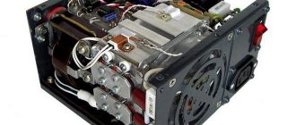
Signal and trigger unit S2000-SP1
The alarm and trigger unit S2000-SP1 is designed to monitor the condition of equipment and collect information in fire and security alarms, identify alarms and arm or disarm various objects. It combines all connected devices and sensors into one system, and when used, the number of connected objects increases. The main function of the block is to control operating devices: sirens, lamps, electromagnetic locks and warning systems. The alarm signal is sent to the central control panel by opening the contacts.
Frequency converters for asynchronous motors
The main function performed by frequency converters for asynchronous motors is to change the frequency of the three-phase output voltage. Their main advantages are:
- reduction of energy consumption;
- increased security;
- reduction of accidents;
- increase in resource.
A frequency converter in an electric drive makes it possible to solve a large number of production problems associated with metalworking machines, cranes, conveyors, extruders, elevators, etc. They are easy to install and operate, economical and do not require special attention. Frequency converters are used for basic industrial mechanisms and allow you to switch to modern energy-saving technologies.