The circuit of a welding inverter is fundamentally different from the design of its predecessor, the welding transformer. The basis of the design of previous welding machines was a step-down transformer, which made them large and heavy. Modern welding inverters, thanks to the use of advanced developments in their production, are lightweight and compact devices characterized by wide functionality.
Welding inverter without cover
The main element of the electrical circuit of any welding inverter is a pulse converter that generates high-frequency current. It is thanks to this that the use of an inverter makes it possible to easily ignite the welding arc and maintain it in a stable state throughout the welding process. The welding inverter circuit, depending on the model, may have certain features, but the principle of its operation, which will be discussed below, remains unchanged.
What types of inverters are available on the modern market?
For a certain type of welding, you should choose the right inverter equipment, each type of which has a specific electrical circuit and, accordingly, special technical characteristics and functionality.
Inverters produced by modern manufacturers can be used equally successfully both in industrial enterprises and in everyday life. Developers are constantly improving the electrical circuit diagrams of inverter devices, which allows them to be equipped with new functions and improve their technical characteristics.
The number of connectors and controls on the front panel speaks volumes about the capabilities of the welding inverter
Inverter devices as the main equipment are widely used to perform the following technological operations:
- electric arc welding with consumable and non-consumable electrodes;
- welding using semi-automatic and automatic technologies;
- plasma cutting, etc.
In addition, inverter machines are the most efficient type of equipment used for welding aluminum, stainless steel and other difficult-to-weld metals. Welding inverters, regardless of the features of their electrical circuit, allow you to obtain high-quality, reliable and neat welds made using any technology. At the same time, what is important is that the compact and not too heavy inverter machine, if necessary, can be easily moved at any time to the place where welding work will be performed.
Mobility is one of the advantages of inverter devices
Typical LCD monitor device
Backlighting of LCD monitors is provided by:
- Fluorescent lamps located on the right and left or at the top and bottom.
- LEDs. Usually it is located at the back of the monitor screen, in some models - along the edges.
If at least one of the lamps burns out, the image quality drops, the colors become dull and not as bright as they should be.
If all 2-4 lamps fail at once, the image on the screen disappears completely. It seems that it broke down and stopped working. However, when the display is illuminated from outside with a bright light source, you can see the picture. It becomes more noticeable at an acute angle or when switching with the mouse.
Depending on the modification, the monitor may use an external or built-in power supply. In the latter case, the connection to the electrical network occurs directly, bypassing additional devices, and the monitor inverter is connected directly to the display controller. A scaler is installed in the controller itself, which ensures scaling of images entering the screen.
What does the design of a welding inverter include?
The welding inverter circuit, which determines its technical characteristics and functionality, includes such mandatory elements as:
- a unit that provides electrical power to the power part of the device (it consists of a rectifier, a capacitive filter and a nonlinear charging circuit);
- power part, made on the basis of a single-cycle converter (this part of the electrical circuit also includes a power transformer, a secondary rectifier and an output choke);
- power supply unit for elements of the low-current part of the electrical circuit of the inverter apparatus;
- PWM controller, which includes a current transformer and a load current sensor;
- a block responsible for thermal protection and control of cooling fans (this block of the circuit diagram includes inverter fans and temperature sensors);
- controls and indications.
List of required materials and tools
Do-it-yourself inverter welding will consume 32 A, and after conversion it will produce a current of 250 A, which will ensure a durable and high-quality seam. To complete the task you will need the following components:
- transformer with a ferrite core for the power section;
- copper sheet for windings;
- PEV wire;
- steel sheets for the body or a finished box;
- insulating material;
- textolite;
- fans and radiators;
- capacitors, resistors, transistors and diodes;
- PIN controller;
- front panel buttons and switches;
- wires for connecting nodes;
- large cross-section power cables.
It is recommended to purchase a ground clamp and holder from a specialty tool store. Some craftsmen make a holder from steel wire with a cross-section of 6 mm. Before you start assembling your welding inverter, it is recommended to watch the training video, study the step-by-step instructions and print the diagram. The tools you need to prepare are a soldering iron, pliers, a knife, a set of screwdrivers and fasteners.
How does a welding inverter work?
The formation of a high current, with the help of which an electric arc is created to melt the edges of the parts being joined and the filler material, is what any welding machine is designed for. For the same purposes, an inverter apparatus is also needed, which allows the generation of welding current with a wide range of characteristics.
In its simplest form, the principle of operation of the inverter looks like this.
- Alternating current with a frequency of 50 Hz from a regular electrical network is supplied to the rectifier, where it is converted into direct current.
- After the rectifier, the direct current is smoothed using a special filter.
- From the filter, direct current flows directly to the inverter, whose task is to convert it again into alternating current, but at a higher frequency.
- After this, using a transformer, the voltage of the alternating high-frequency current is reduced, which makes it possible to increase its strength.
Block diagram of an inverter type welding machine
In order to understand the importance of each element of the electrical circuit diagram of an inverter device, it is worth considering its operation in more detail.
Useful properties of the devices
Often, inverters from 12 V to 220 V provide protection or weakening of the functioning of information systems from the quality of AC networks. If there is a sudden power outage, using a spare battery and rectifier will restore backup power and you can shut down your computer without losing essential data.
In complex and critical structures, these devices operate in a longer and more controlled mode. This work is carried out both separately and in parallel with the main electrical network. In addition, the inverter can work as an intermediate link in a converter complex.
A distinctive feature in this case is the presence of a high voltage frequency - up to 100 kHz. For efficient operation, semiconductor switches , magnetic materials and special controllers are additionally used. To be convenient for use, the inverter must have high efficiency, reliability and compact dimensions.
The output voltage must comply with the technical characteristics of the general network, especially for Grid-tie inverters, which are used to convert energy from solar panels, wind generators and other environmentally friendly sources.
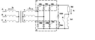
Processes occurring in the electrical circuit of a welding inverter
The circuit of an inverter-type welding machine allows you to increase the current frequency from the standard 50 Hz to 60–80 kHz. Due to the fact that high-frequency current is subject to regulation at the output of such a device, compact transformers can be effectively used for this. An increase in the frequency of the current occurs in that part of the inverter electrical circuit where the circuit with powerful power transistors is located. As you know, only direct current is supplied to transistors, which is why a rectifier is needed at the input of the device.
Schematic diagram of the factory welding inverter "Resanta" (click to enlarge)
Inverter circuit from the German manufacturer FUBAG with a number of additional functions (click to enlarge)
An example of a circuit diagram of a welding inverter for self-production (click to enlarge)
The electrical circuit diagram of the inverter device consists of two main parts: the power section and the control circuit. The first element of the power section of the circuit is a diode bridge. The task of such a bridge is precisely to convert alternating current into direct current.
In the direct current converted from alternating current in the diode bridge, pulses may occur that need to be smoothed out. To do this, a filter consisting of capacitors of predominantly electrolytic type is installed after the diode bridge. It is important to know that the voltage that comes out of the diode bridge is approximately 1.4 times greater than its value at the input. When converting AC to DC, rectifier diodes become very hot, which can seriously affect their performance.
Components of a welding inverter using the example of a homemade machine
To protect them, as well as other elements of the rectifier from overheating, radiators are used in this part of the electrical circuit. In addition, a thermal fuse is installed on the diode bridge itself, the task of which is to turn off the power supply if the diode bridge has heated up to a temperature exceeding 80–90 degrees.
High-frequency interference generated during operation of the inverter device can enter the electrical network through its input. To prevent this from happening, an electromagnetic compatibility filter is installed in front of the rectifier block of the circuit. Such a filter consists of a choke and several capacitors.
Inverter power supply
The inverter itself, which converts direct current into alternating current, but with a much higher frequency, is assembled from transistors using an “oblique bridge” circuit. The switching frequency of transistors, due to which the alternating current is generated, can be tens or hundreds of kilohertz. The high-frequency alternating current thus obtained has a rectangular amplitude.
A voltage-reducing transformer installed behind the inverter unit allows you to obtain a current of sufficient strength at the output of the device so that you can effectively perform welding work with its help. In order to obtain direct current using an inverter apparatus, a powerful rectifier, also assembled on a diode bridge, is connected after the step-down transformer.
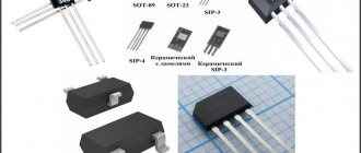
Transistors for the power module of the welding inverter
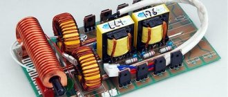
Converter with the latest parts
A homemade inverter can operate in a stable mode if the transistor at the outputs operates from an amplified source with the main generator. For this purpose, it is allowed to use elements of the KT819GM series installed on dimensional radiators.
When creating converters, a simplified scheme is used. As the process progresses, you should take care of purchasing the necessary materials:
- microcircuits KR121EU1;
- transistors IRL2505;
- soldering iron;
- tin.
KR12116U1 microcircuits have a remarkable property: they contain a pair of channels for regulating the switch and allow you to quite simply make a simple voltage converter. Microcircuits in the temperature range from +25 to +30°C produce a maximum voltage value within the range of 3 and 9 V.
The frequency of the master oscillators is determined by the parameter of the element in the circuits. The IRL2505 transistor is installed when used on the outputs. It must receive a signal with the proper level, due to which the output transistor is adjusted.
The formed low levels do not allow the transistor to transition from closed modes to any other states. As a result, the occurrence of instantaneous current flows during simultaneous opening of the keys is completely eliminated. If high levels are observed to reach the first output, then this helps to turn off pulse generation. The circuit determines the connection of the common wire to pin 1.
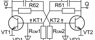
To install push-pull cascades, T1 transformers and two transistors are used: VT1 and VT2. In open channels you can see a resistance value of 0.008 Ohm. It is insignificant, and therefore the power value of the transistor is small, even if a large current passes. Output transformers with a power of 100 W allow the IRL2505 to apply a current of 104 A, and pulse transformers are 360 A.
The main features of inverters include the ability to use any transformer that has two 12 V windings at its outputs.
If the output power is about 200 W, then in such cases the transistor is not installed on the radiator. It is important to consider that the value of electric current with a power of 400 W reaches about 40 A.
Inverter protection and control elements
Several elements in its circuit diagram allow you to avoid the influence of negative factors on the operation of the inverter.
To ensure that transistors that convert direct current into alternating current do not burn out during their operation, special damping (RC) circuits are used. All electrical circuit blocks that operate under heavy load and become very hot are not only provided with forced cooling, but are also connected to temperature sensors that turn off their power if their heating temperature exceeds a critical value.
Radiators and cooling fans take up significant space inside the inverter
Due to the fact that the filter capacitors, after being charged, can produce a high current, which can burn the inverter transistors, the device must be provided with a smooth start. For this purpose, stabilizers are used.
The circuit of any inverter has a PWM controller, which is responsible for controlling all elements of its electrical circuit. From the PWM controller, electrical signals are sent to a field-effect transistor, and from it to an isolation transformer, which simultaneously has two output windings. The PWM controller, through other elements of the electrical circuit, also supplies control signals to the power diodes and power transistors of the inverter unit. In order for the controller to effectively control all elements of the inverter's electrical circuit, it is also necessary to supply electrical signals to it.
To generate such signals, an operational amplifier is used, the input of which is supplied with the output current generated in the inverter. If the values of the latter diverge from the specified parameters, the operational amplifier generates a control signal to the controller. In addition, the operational amplifier receives signals from all protective circuits. This is necessary so that he can disconnect the inverter from the power supply at the moment when a critical situation arises in its electrical circuit.
Design
Approximate basic diagram:
- Low frequency rectifier.
- Inverter.
- Transformer.
- High-frequency current rectifier.
- A branch of a circuit with reduced resistance (shunt).
- Electronic control unit.
Similar products differ in design, but are based on the use of high-frequency pulse converters.
Output diode and characteristics of its operation
During self-assembly, users install transformers that have a secondary winding with the following parameters: the cross-section of the copper wire is 0.3 mm, and the width of the structure is up to 40 mm, so diodes at the output ensure its rectification. The operating cycle of the device is carried out at high frequency currents, but only high-speed diodes can cope with such loads, since recovery occurs in 50 nanoseconds.
Versatility
Each manufacturer of welding inverter models takes care of increasing reliability during long-term operation, subject to compliance with safety measures when working with original products. The design must include a temperature rise control unit, which protects the inverter from overheating and regulates the functioning of the cooling system.
The electrical circuit of the product has a built-in transformer that has bimetallic temperature sensors with a set operating temperature of no higher than 75 degrees. The cooling radiator has its own integrated sensor that monitors the temperature rise and will turn off the current supply if it rises unacceptable.
Advantages and disadvantages of inverter-type welding machines
Inverter welding machines, which replaced the usual transformers, have a number of significant advantages.
- Thanks to a completely different approach to the formation and regulation of welding current, the weight of such devices is only 5–12 kg, while welding transformers weigh 18–35 kg.
- Inverters have very high efficiency (about 90%). This is explained by the fact that they spend significantly less excess energy on heating the components. Welding transformers, unlike inverter devices, get very hot.
- Due to such high efficiency, inverters consume 2 times less electrical energy than conventional transformers for welding.
- The high versatility of inverter machines is explained by the ability to regulate the welding current over a wide range with their help. Thanks to this, the same device can be used for welding parts made of different metals, as well as for welding using different technologies.
- Most modern inverter models are equipped with options that minimize the impact of welder errors on the technological process. Such options, in particular, include “Anti-stick” and “Arc Force” (fast ignition).
- Exceptional stability of the voltage supplied to the welding arc is ensured by the automatic elements of the inverter electrical circuit. In this case, automation not only takes into account and smoothes out differences in input voltage, but also corrects even such interference as the attenuation of the welding arc due to strong wind.
- Welding using inverter equipment can be performed with any type of electrode.
- Some models of modern welding inverters have a programming function, which allows you to accurately and quickly configure their modes when performing a certain type of work.
Like any complex technical devices, welding inverters have a number of disadvantages that you also need to be aware of.
- Inverters are highly expensive, 20–50% higher than the cost of conventional welding transformers.
- The most vulnerable and often failing elements of inverter devices are transistors, the cost of which can be up to 60% of the price of the entire device. Accordingly, repairing a welding inverter is quite an expensive undertaking.
- Due to the complexity of their electrical circuitry, inverters are not recommended for use in bad weather conditions and at low temperatures, which seriously limits their scope of application. In order to use such a device in field conditions, it is necessary to prepare a special closed and heated area.
When welding work performed using an inverter, long wires cannot be used, as they induce interference that negatively affects the operation of the device. For this reason, the wires for inverters are made quite short (about 2 meters), which makes welding work somewhat inconvenient.
Types of current sources
The pulse converter is considered the main element of the electrical circuit of welding inverters, because it is capable of actively generating high-frequency currents . This advantage during operation of the equipment allows the welder to easily excite the arc and maintain its stable combustion.
All welding current sources have an identical design and their welding circuit is the same, the only difference is in what volt-ampere characteristics the device switches modes. Manufacturers of similar products produce universal models suitable for different types of welding work:
- manual arc welding (MMA);
- using a non-consumable tungsten electrode, and the protection is an inert gas (TIG);
- a technique for joining metals under the protection of an inert/active gas, using a consumable electrode (MIG/MAG).
Advantages of semi-automatic devices
- Light weight - for amateurs only 5-6 kg.
- Additional functions.
- Smooth voltage regulation.
- Good internal ventilation thanks to the integrating device.
- Precise current adjustment depending on the material of the structures being connected.
Inverters have high efficiency regardless of manufacturer.
Diagrams of welding machines for semi-automatic welding are of interest only to specialists, as they are replete with technical symbols understandable to a narrow contingent.
Inverters for plasma arc cutting
Such devices are small in size and consume little electrical energy; they are used to join or cut ferrous and non-ferrous metals. The plasma inverter has great versatility, therefore it is used in various industries:
- heat treatment of any metals;
- soldering, welding or cutting of ferrous and non-ferrous metals;
- industrial steel bluing;
- for cutting ceramic tiles, glass blanks, concrete, etc.
The only disadvantages include the high cost of similar equipment.
Device repair
Repair of these devices to convert one type of voltage to another is best done in service centers, where the personnel are highly qualified and will subsequently provide guarantees for the work performed. Most often, any modern high-quality converters consist of several hundred electronic parts, and if there are no obvious burnt elements, then it will be very difficult to find a breakdown and fix it.
It will be interesting➡ How to choose a digital-to-analog converter (DAC)
Some Chinese inexpensive devices of this type, in general, are in principle deprived of the possibility of repairing them, which cannot be said about domestic manufacturers. Yes, they may be a little bulky and not compact, but they can be repaired, since many of their parts can be replaced with similar ones.
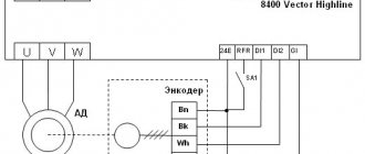
How to identify connectors and pin assignments
The inverter board can be used from an old monitor or a new one can be purchased. The first option is much cheaper, but there is a risk that the part will not work. In the second case, the board will cost more, but the quality will be guaranteed by the manufacturer.
The board, which combines an external backlight inverter and a power supply, is equipped with only one connector that allows it to be connected to the matrix controller board. Knowing the purpose of the contacts on both boards, you can easily connect them using conductors. Many boards have a connection diagram with a decoding printed on them.
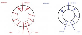
Pulse transformer: operating principle of one pulse in 2 cycles
Rule #5: The pulse transformer for the power supply transmits each PWM pulse due to two conversions of electromagnetic energy .
During the conversion of electrical energy to magnetic energy and back to electrical energy with reduced voltage, galvanic separation of the primary input circuits from the secondary output circuit is ensured.
Each PWM current pulse arriving when the power transistor is briefly opened flows through the closed circuit of the primary winding of the transformer.
Its energy is spent:
- first to magnetize the magnetic core;
- then to demagnetize it with current flowing through the secondary winding and additional charging of the capacitor.
According to this principle, each PWM pulse from the primary network recharges the storage capacitor.
UPS generators can operate using simple single-cycle or more complex push-pull construction technology.
Single-cycle switching power supply circuit: composition and principle of operation
On side 220 there are: a fuse, a rectifying diode bridge, a smoothing capacitor, a bipolar transistor, chains of an oscillating circuit and collector current, as well as windings of a pulse transformer.
A single-cycle switching power supply circuit is created to transmit power of 10÷50 watts, no more. It is used to make chargers for mobile phones, tablets and other digital gadgets.
The rectifier diode D7 is used in the output circuit of the transformer. It can be turned on in the forward direction, as shown in the picture, or reverse, which is important to consider.
When connected directly, the pulse transformer accumulates inductive energy and transfers it to the output circuit to the connected load with a time delay.
If the diode is turned back on, then the transformation of energy from the primary circuit to the secondary circuit occurs during the off state of the transistor.
The single-cycle UPS circuit is characterized by its simplicity of design, but large voltage amplitudes applied to the turns of the primary winding of the pulse transformer.
Their protection is carried out by additional chains of resistors R2÷R4 and capacitors C2, C3.
Push-pull switching power supply circuit: 3 design options
Higher efficiency and reduced power losses are the undeniable advantages of these UPSs compared to single-cycle models.
The simplest version of the full-wave technique is shown in the picture.
If you additionally connect two diodes and one smoothing capacitor to it, then a bipolar circuit is obtained using the same transformer.
It is common in power amplifiers and operates on the flyback principle. In it, smaller currents flow through each capacitor, providing an increased service life of the capacitors during operation.
You can extend the service life of electrolytic capacitors in a UPS by replacing one high-power capacitor with several components. The current will be distributed throughout, which will cause less heating. And heat removal from each individual is better.
The forward-flow power supply circuit has a choke in its design, which performs the function of energy storage. To do this, two diodes direct incoming PWM pulses to its input in the same polarity.
The choke of these devices is made in large dimensions and is installed separately inside the UPS board. It complements the operation of the storage capacitor.
This is clearly visible in the upper form of the signal shown by the rectification oscillogram of the same block without and with a choke.
The forward circuit is used in high-power power supplies, for example, inside a computer.
It uses Schottky diodes to rectify the current. They are used due to:
- reduced voltage drop on direct connection;
- and increased speed when processing high-frequency pulses.
3 diagrams of power stages of push-pull UPSs
In order of complexity of their implementation, generators perform the following:
- half-bridge;
- pavement;
- or the push-pull principle of constructing the output stage.
Half-bridge switching power supply circuit: overview
Capacitors C1, C2 are assembled in series with a capacitive divider. A constant supply voltage is supplied to it and the collector-emitter transitions of transistors T1, T2.
The primary winding of transformer Tr2 is connected to the midpoint of the capacitive divider and transistors. The output voltage of the generator is removed from its secondary winding, which is proportional to the input signal TP1, transformed to the bases T1 and T2.
The half-bridge UPS circuit works for loads ranging from a few watts to kilowatts. Its disadvantage is the possibility of damage to elements during overloads, which requires the use of complex protections.
Bridge Switching Power Supply Circuit: Brief Explanation
Instead of the capacitive divider of the previous technology, transistors T3 and T4 work here. They open in pairs together with T1 and T2: (pair T1-T4), (pair T2-T3).
The voltage of the emitter-collector transitions for closed transistors is not higher than the value of the supply voltage, and on the winding w1 TP3 it increases to the value U supply. Due to this, the efficiency value increases.
The bridge circuit is difficult to set up due to difficulties in setting up the control circuits of transistors T1÷T4.
Push-pull circuit: important features
The primary winding of the output TP2 has a middle terminal, to which the positive potential of the power source is supplied, and its minus is applied to the middle point of the secondary winding T1.
During the passage of one half-cycle of oscillation, one of the transistors T1 or T2 and the corresponding part of the transformer half-winding operate.
Here the highest efficiency, low ripple and low interference are created. The amplitude value of the pulse voltage on any half of the winding w1 TP2 reaches the value U power.
The self-inductive emf is added to the collector-emitter junction voltage of each transistor, and it increases to 2U power supply. Therefore, T1 and T2 must be selected at 600÷700 volts.
The push-pull circuit of the key cascade is more popular. It is used in the most powerful converters.