Capacitor radio components contain plates of an electrically conductive substance separated by a dielectric layer. They differ from other devices used in electrical circuits in their ability to accumulate electrical charge. To correctly select the appropriate part, you need to have an idea of what the unit of measurement that describes the capacitance of the capacitor is and be able to read the symbols on the markings.
Capacitive radio components
Other measurement methods
Maximum data accuracy can be achieved by using an immittance indicator.
The problem is that such devices require large budget investments, often costing more than 100 thousand rubles. Another way is to assemble a circuit from a resistor and a capacitor. First, the resistance of the first is measured, and the voltage of the power source is also measured. Having assembled the circuit, the capacitive element is short-circuited, the circuit is connected to power, the voltage is measured and multiplied by 0.95. After unwinding, measure the time during which the voltage drops from 100 to 95%. This figure must be divided by triple the resistor value. This will be the capacitance indicator in farads.
The unit farad is used to describe the capacitance values of both capacitor devices and conductors. To select the correct parts, you must be able to decipher the markings on the body.
Capacitor in AC circuit
Let's assemble a circuit with a capacitor in which an alternating current generator creates a sinusoidal voltage. Let's look at what happens in the circuit when we close the key. We will consider the initial moment when the generator voltage is zero. In the first quarter of the period, the voltage at the generator terminals will increase, starting from zero, and the capacitor will begin to charge. A current will appear in the circuit, but at the first moment of charging the capacitor, despite the fact that the voltage on its plates has just appeared and is still very small, the current in the circuit (charge current) will be the greatest.
As the charge on the capacitor increases, the current in the circuit decreases and reaches zero at the moment when the capacitor is fully charged. In this case, the voltage on the capacitor plates, strictly following the generator voltage, becomes at this moment maximum, but of the opposite sign, i.e., directed towards the generator voltage. Thus, the current rushes with the greatest force into the charge-free capacitor, but immediately begins to decrease as the capacitor plates are filled with charges and drops to zero, fully charging it.
Let us compare this phenomenon with what happens to the flow of water in a pipe connecting two communicating vessels, one of which is filled and the other empty. One has only to pull out the valve blocking the path of water, and water will immediately rush from the left vessel under high pressure through the pipe into the empty right vessel. However, immediately the water pressure in the pipe will begin to gradually weaken, due to the leveling of the levels in the vessels, and will drop to zero. The water flow will stop. Similarly, the current first flows into an uncharged capacitor, and then gradually weakens as it charges.
With the beginning of the second quarter of the period, when the voltage of the generator begins slowly at first, and then decreases faster and faster, the charged capacitor will be discharged to the generator, which will cause a discharge current in the circuit. As the generator voltage decreases, the capacitor is discharged more and more and the discharge current in the circuit increases. The direction of the discharge current in this quarter of the period is opposite to the direction of the charge current in the first quarter of the period. Accordingly, the current curve, having passed the zero value, is now located below the time axis.
By the end of the first half-cycle, the voltage on the generator, as well as on the capacitor, quickly approaches zero, and the current in the circuit slowly reaches its maximum value. Remembering that the magnitude of the current in the circuit is greater, the greater the amount of charge transferred along the circuit, it will become clear why the current reaches its maximum when the voltage on the capacitor plates, and therefore the charge of the capacitor, quickly decreases.
With the beginning of the third quarter of the period, the capacitor begins to charge again, but the polarity of its plates, as well as the polarity of the generator, changes to the opposite, and the current, continuing to flow in the same direction, begins to decrease as the capacitor is charged. At the end of the third quarter of the period, when the voltages across the generator and capacitor reach their maximum, the current becomes zero.
In the last quarter of the period, the voltage, decreasing, drops to zero, and the current, changing its direction in the circuit, reaches its maximum value. This ends the period, after which the next one begins, exactly repeating the previous one, etc.
So, under the action of the alternating voltage of the generator, the capacitor is charged twice per period (the first and third quarters of the period) and discharged twice (the second and fourth quarters of the period). But since the alternating charges and discharges of the capacitor are accompanied each time by the passage of charging and discharging currents through the circuit, we can conclude that an alternating current passes through the circuit with the capacitance.
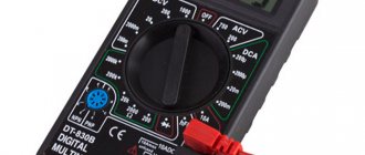
How to measure capacitance of a capacitor with a multimeter
To perform such an operation, you need a device with a capacitance measurement mode (often marked as C or Cx). It must have a resistance greater than 2 kilo-ohms. Before measurements, it is necessary to discharge the contacts of the device. A screwdriver with a handle coated with an insulating material (for example, rubberized) is suitable for this. You need to take the tool by the handle and touch the contacts, after which they will close. Then you need to keep the capacitor de-energized for about half an hour so that it is completely discharged.
Important! If the capacitive radio component malfunctions, the measuring device will show an infinite value and begin to make beeping sounds. Devices that have punctures or bulges on the housing cannot be tested - such capacitors are unsuitable for use.
The electrical circuit is disconnected from power. After this, you need to make sure that it is absent by placing the probes on the supplier with a preset voltage measurement program. The parameter must have a zero value.
The measuring device is placed in the capacitance parameter measurement mode. When using a device with several setting intervals, choose the one that is most likely to fit (based on the marking data). If there is a Rel button, it is used to release the probes from the capacitive load. The probes are placed to the terminals of the part, strictly observing the polarization. If, after waiting, the screen reports overload, the capacity is too large for this device to identify, or a different interval must be selected.
Multimeter measurement
Parasitic capacitance
Main article: Parasitic capacitance
Any two adjacent conductors can function as a capacitor, although the capacitance is small unless the conductors are located close together over long distances or over a large area. This (often unwanted) capacitance is called parasitic or parasitic capacitance. Parasitic capacitance can cause signals to leak between isolated circuits (an effect called crosstalk), and this can be a limiting factor for circuits to function properly at high frequencies.
Parasitic capacitance between input and output in amplifier circuits can be a problem because it can form a path for feedback, which can cause instability and parasitic oscillations in the amplifier. For analytical purposes it is often convenient to replace this capacitance with a combination of one input-ground capacitance and one output-ground capacitance; the original configuration, including the input-output capacitance, is often called the pi configuration. Miller's theorem can be used to make this substitution: it states that if the gain of two nodes is 1/ K
, then the resistance from
Z
connection of two nodes can be replaced by
Z
/(1 −
k
) impedance between the first node and ground and
KZ
/(
K
- 1) impedance between the second node and ground.
Since resistance varies inversely with capacitance, the internode capacitance, C
, is replaced by capacitance KC from input to ground and capacitance (
K
−1)
C
/
K
from output to ground. When the input-to-output gain is very high, the equivalent input-to-ground impedance is very small, while the output-to-ground impedance is essentially equal to the original (input-to-output) impedance.
Application of capacitors
This category of elements is very widely used in all areas of electronics and a number of other industries. Among the main areas of application are:
- television and sound reproducing equipment;
- radar devices (here capacitors help generate pulses and increase their power);
- telephone and telegraph devices - in them devices are used to separate types of circuits (by frequency, variability-constancy) and extinguish sparks in contacts;
- measuring electronic instruments;
- lasers (increasing pulse power);
- overvoltage protection in electrical power plants;
- electric welding work using a discharge;
- blocking machine-generated radio interference;
- starting electric motors and creating a phase shift in the additional winding;
- generators used during electrical testing to produce current and voltage pulses.
Capacitor element dimensions
Farad
Capacitor elements are used in a very wide range of areas - from printed circuit boards (miniature SMD components) to powerful motors and pulse generators. To correctly select a capacitor, you need to be able to decipher the markings and symbols on the diagrams, in particular, navigate the symbols of device capacitance.
Capacitor charge. Current
In terms of its purpose, a capacitor resembles a battery, but it is still very different in its operating principle, maximum capacity, and charging/discharging speed.
Let's consider the principle of operation of a flat-plate capacitor. If you connect a power source to it, negatively charged particles in the form of electrons will begin to collect on one plate of the conductor, and positively charged particles in the form of ions will begin to collect on the other. Since there is a dielectric between the plates, charged particles cannot “jump” to the opposite side of the capacitor. However, electrons move from the power source to the capacitor plate. Therefore, electric current flows in the circuit.
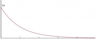
At the very beginning of connecting the capacitor into the circuit, there is the most free space on its plates. Consequently, the initial current at this moment encounters the least resistance and is maximum. As the capacitor fills with charged particles, the current gradually drops until the free space on the plates runs out and the current stops completely.
The time between the states of an “empty” capacitor with a maximum current value, and a “full” capacitor with a minimum current value (i.e., its absence), is called the transition period of the capacitor charge.
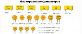
Marking of capacitors depending on capacity
When purchasing elements that correspond to the calculated data for a particular circuit, the user needs to be able to decipher the symbols on the device cases, informing how much capacity they are capable of accumulating. Different manufacturers have adopted different marking systems for radio components.
Encoding of small devices
On the housings of Soviet radio components, it was customary to designate picofarads as an integer (for example, 25). If on such a part the parameter is indicated by a number containing a decimal fraction, microfarads are implied. It was not customary to write the letter designations themselves (pF, μF and the like) on the housings.
Important! As for Russian products, nanofarads and microfarads are indicated by traditional abbreviations in which the letter F is reduced (it turns out “n” and “mk”, respectively). Capacity, calculated in picofarads, is indicated only by number, as with Soviet parts
When a Latin prefix indicating a multiple of one is placed before a number, the latter must be counted as hundredths. For example, n45 means 0.45 nanofarads. When the prefix is in the middle of a number, there should be a comma in its place: 4u3 – 4.3 microfarads. A three-digit picofarad encoding is also used: when the last digit is not more than 6, in order to obtain a capacitive value, the first two digits must be assigned the number of zeros corresponding to this digit (340 - 34 picofarads, 342 - 3400). The numbers 7, 8 and 9 correspond to multiplications of a two-digit number by 0.001, 0.01 and 0.1, respectively.
Colored stripes are also used to designate product denominations. The indication of the capacitive parameter is regulated by the EIA standard.
Encoding of large devices
For large components, for example electrolytic ones made of aluminum, parameter data, including capacitance indicator, is indicated on the surface of the housing. Typically, the capacitance of such parts is expressed in microfarads. The letters M or MFD symbolize this particular unit. The three-digit abbreviation can also be indicated in lowercase letters - mfd.
Marking of large parts
Methods for marking capacitor capacity
On Soviet-made parts, most often having a fairly large surface area, the numerical values of the capacitance, its unit of measurement and the nominal voltage in volts were applied. For example, 23 pF, that is, 23 picofarads.
Deciphering the markings of modern ceramic capacitors of domestic and foreign production is a more complex undertaking.
A little about the parameters
It’s worth saying a few words about the last two parameters (power and tolerance). Tolerance in the characteristics of capacitors is the permissible/possible deviation of the capacitance from the specified rating. There are types with a small tolerance - a few percent, and others with a large tolerance - up to 20%. It is not always possible to replace a capacitor with a low tolerance with an analogue in terms of capacity and voltage, but with a higher tolerance. This is only permissible in household appliances. And then, only where the amount of charge is not too critical. But it is better to look for a replacement with a similar tolerance.
| Capacitance tolerance coding | Tolerance % |
| E | 0.005 |
| L | 0.01 |
| P | 0.002 |
| W | 0.005 |
| B | 0.1 |
| C | 0.25 |
| D | 0.5 |
| F | 1 |
| G | 2 |
| H | 2.5 |
| J | 5 |
| K | 10 |
| M | 20 |
| N | 30 |
| Q | -10 … +30 |
| T | -10…+50 |
| S | -20…+50 |
| Z | -20…+80 |
It often happens that a capacitor periodically “flies out” in the same place. According to our logic, we want to replace it with an element with higher voltage. But there may be 2 options here. Firstly: there are voltage surges in the circuit that exceed the rated voltage of the part. Secondly, the reactive power of the capacitor is not taken into account if it operates in high-frequency circuits.
We recommend reading: What are instrumentation and instrumentation systems: definition of the abbreviation, purpose
For the most part, the power parameter is not indicated and can be found in the specification for the part. It is usually used by narrow specialists.
The temperature coefficient may also be indicated - TKE, but it is not set in all cases. It displays the change in capacity depending on the temperature of the element. Usually included if there is a significant dependency. If the changes are minor, they are simply omitted. Many parameters can be easily recognized with a radio element tester.
Multiples and submultiples
Most often in electronics, elements with small capacitances are used, which is why those starting to work with circuits have questions: pF is how many farads, 100 nf is how many microfarads, and so on. In this regard, you should have with you a table of conversion of one unit to another. The most commonly used submultiple units include:
How to choose and calculate the capacitance of a capacitor for a three-phase motor
- microfarad (μF) – 0.000001 F;
- nanofarad (nF) – 0.000000001 F;
- picofarad (pF) – 0.000000000001 F.
Of the multiple units, the kilofarad (kF) is used, equal to a thousand farads. Such indicators are typical for ionistors. For conventional capacitors, the capacitance is usually measured in a maximum of tens of farads.
In the Soviet Union, there was a tendency on electrical circuits and capacitor housings to indicate the capacitance value as a whole number (for example, 35). To mean picofarads, and a fraction with one digit after the decimal point meant microfarads. Letters were not used in such container markings. On modern domestic capacitors, when indicating the capacitance in picofarads, the measuring units are usually not written after the number. If the letters “mk” are indicated, microfarads are implied, if “n” - nanofarads are implied. Abroad they use markings made of colored stripes.
Table for converting some fractional capacitance units to others
Code marking, addition
According to IEC standards, in practice there are four ways to encode the nominal capacity.
A. 3-digit marking
The first two digits indicate the capacitance value in pygofarads (pf), the last one indicates the number of zeros. When the capacitor has a capacitance of less than 10 pF, the last digit may be "9". For capacitances less than 1.0 pF, the first digit is “0”. The letter R is used as a decimal point. For example, code 010 is 1.0 pF, code 0R5 is 0.5 pF.
| Code | Capacitance [pF] | Capacitance [nF] | Capacitance [µF] |
| 109 | 1,0 | 0,001 | 0,000001 |
| 159 | 1,5 | 0,0015 | 0,000001 |
| 229 | 2,2 | 0,0022 | 0,000001 |
| 339 | 3,3 | 0,0033 | 0,000001 |
| 479 | 4,7 | 0,0047 | 0,000001 |
| 689 | 6,8 | 0,0068 | 0,000001 |
| 100* | 10 | 0,01 | 0,00001 |
| 150 | 15 | 0,015 | 0,000015 |
| 220 | 22 | 0,022 | 0,000022 |
| 330 | 33 | 0,033 | 0,000033 |
| 470 | 47 | 0,047 | 0,000047 |
| 680 | 68 | 0,068 | 0,000068 |
| 101 | 100 | 0,1 | 0,0001 |
| 151 | 150 | 0,15 | 0,00015 |
| 221 | 220 | 0,22 | 0,00022 |
| 331 | 330 | 0,33 | 0,00033 |
| 471 | 470 | 0,47 | 0,00047 |
| 681 | 680 | 0,68 | 0,00068 |
| 102 | 1000 | 1,0 | 0,001 |
| 152 | 1500 | 1,5 | 0,0015 |
| 222 | 2200 | 2,2 | 0,0022 |
| 332 | 3300 | 3,3 | 0,0033 |
| 472 | 4700 | 4,7 | 0,0047 |
| 682 | 6800 | 6,8 | 0,0068 |
| 103 | 10000 | 10 | 0,01 |
| 153 | 15000 | 15 | 0,015 |
| 223 | 22000 | 22 | 0,022 |
| 333 | 33000 | 33 | 0,033 |
| 473 | 47000 | 47 | 0,047 |
| 683 | 68000 | 68 | 0,068 |
| 104 | 100000 | 100 | 0,1 |
| 154 | 150000 | 150 | 0,15 |
| 224 | 220000 | 220 | 0,22 |
| 334 | 330000 | 330 | 0,33 |
| 474 | 470000 | 470 | 0,47 |
| 684 | 680000 | 680 | 0,68 |
| 105 | 1000000 | 1000 | 1,0 |
* Sometimes the last zero is not indicated.
B. 4-digit marking
4-digit coding options are possible. But even in this case, the last digit indicates the number of zeros, and the first three indicate the capacity in picofarads.
| Code | Capacitance[pF] | Capacitance[nF] | Capacitance[uF] |
| 1622 | 16200 | 16,2 | 0,0162 |
| 4753 | 475000 | 475 | 0,475 |
C. Capacitance marking in microfarads
The letter R may be used instead of the decimal point.
| Code | Capacitance [µF] |
| R1 | 0,1 |
| R47 | 0,47 |
| 1 | 1,0 |
| 4R7 | 4,7 |
| 10 | 10 |
| 100 | 100 |
D. Mixed alphanumeric marking of capacity, tolerance, TKE, operating voltage
Unlike the first three parameters, which are marked in accordance with standards, the operating voltage of different companies has different alphanumeric markings.
| Code | Capacity |
| p10 | 0.1 pF |
| IP5 | 1.5 pF |
| 332p | 332 pF |
| 1NO or 1nO | 1.0 nF |
| 15H or 15n | 15 nF |
| 33H2 or 33n2 | 33.2 nF |
| 590H or 590n | 590 nF |
| m15 | 0.15uF |
| 1m5 | 1.5 µF |
| 33m2 | 33.2 µF |
| 330m | 330 µF |
| 1mO | 1 mF or 1000 μF |
| 10m | 10 mF |
Code marking of electrolytic capacitors for surface mounting
The following coding principles are used by such well-known companies as Hitachi and others. There are three main coding methods:
A. Marking with 2 or 3 characters
The code contains two or three characters (letters or numbers) indicating the operating voltage and rated capacity. Moreover, the letters indicate voltage and capacitance, and the number indicates the multiplier. In the case of a two-digit designation, the operating voltage code is not indicated.
| Code | Capacitance [µF] | Voltage [V] |
| A6 | 1,0 | 16/35 |
| A7 | 10 | 4 |
| AA7 | 10 | 10 |
| AE7 | 15 | 10 |
| AJ6 | 2,2 | 10 |
| AJ7 | 22 | 10 |
| AN6 | 3,3 | 10 |
| AN7 | 33 | 10 |
| AS6 | 4,7 | 10 |
| AW6 | 6,8 | 10 |
| CA7 | 10 | 16 |
| CE6 | 1,5 | 16 |
| CE7 | 15 | 16 |
| CJ6 | 2,2 | 16 |
| CN6 | 3,3 | 16 |
| CS6 | 4,7 | 16 |
| CW6 | 6,8 | 16 |
| DA6 | 1,0 | 20 |
| DA7 | 10 | 20 |
| DE6 | 1,5 | 20 |
| DJ6 | 2,2 | 20 |
| DN6 | 3,3 | 20 |
| DS6 | 4,7 | 20 |
| DW6 | 6,8 | 20 |
| E6 | 1,5 | 10/25 |
| EA6 | 1,0 | 25 |
| EE6 | 1,5 | 25 |
| EJ6 | 2,2 | 25 |
| EN6 | 3,3 | 25 |
| ES6 | 4,7 | 25 |
| EW5 | 0,68 | 25 |
| GA7 | 10 | 4 |
| GE7 | 15 | 4 |
| GJ7 | 22 | 4 |
| GN7 | 33 | 4 |
| GS6 | 4,7 | 4 |
| GS7 | 47 | 4 |
| GW6 | 6,8 | 4 |
| GW7 | 68 | 4 |
| J6 | 2,2 | 6,3/7/20 |
| JA7 | 10 | 6,3/7 |
| JE7 | 15 | 6,3/7 |
| JJ7 | 22 | 6,3/7 |
| JN6 | 3,3 | 6,3/7 |
| JN7 | 33 | 6,3/7 |
| JS6 | 4,7 | 6,3/7 |
| JS7 | 47 | 6,3/7 |
| JW6 | 6,8 | 6,3/7 |
| N5 | 0,33 | 35 |
| N6 | 3,3 | 4/16 |
| S5 | 0,47 | 25/35 |
| VA6 | 1,0 | 35 |
| VE6 | 1,5 | 35 |
| VJ6 | 2,2 | 35 |
| VN6 | 3,3 | 35 |
| VS5 | 0,47 | 35 |
| VW5 | 0,68 | 35 |
| W5 | 0,68 | 20/35 |
We recommend reading: Hall sensor design: principle of operation, application, circuit diagram, connection
B. 4-character marking
The code contains four characters (letters and numbers) indicating the capacity and operating voltage. The first letter indicates the operating voltage, the subsequent digits indicate the nominal capacitance in picofarads (pF), and the last digit indicates the number of zeros. There are 2 options for encoding the capacity: a) the first two digits indicate the nominal value in picofarads, the third - the number of zeros; b) the capacitance is indicated in microfarads, the m sign acts as a decimal point. Below are examples of marking capacitors with a capacity of 4.7 μF and an operating voltage of 10 V.
C. Two-line marking
If the size of the case allows, then the code is located in two lines: the capacitance rating is indicated on the top line, and the operating voltage is indicated on the second line. Capacitance can be indicated directly in microfarads (µF) or in picofarads (pf) indicating the number of zeros (see method B). For example, the first line is 15, the second line is 35V - means that the capacitor has a capacity of 15 uF and an operating voltage of 35 V.
Multiples of capacity units
In most cases in electrical engineering, parts with small capacitance values are operated. Sometimes you will see designations such as 10uf capacitor. An inexperienced person may not immediately understand what the abbreviation uf means. It should be understood that the most common units in the description of capacitive elements are the following units: picofarad (or pF, it is equal to 10-12 F), nanofarad (nF, 10-9 F) and microfarad (μF, 10-6 F). Specifying the capacitance of a capacitor in uf means microfarads. It is advisable to purchase a table for converting measurement units of different scales to each other.
Multiple units are not used that often in practice. For some ionistor parts with a binary electrical layer, the capacitance indicator can be measured in kilofarads (kF, 1000 F). The value of standard capacitor elements usually does not exceed hundreds of farads.
Ionistor with a nominal value of 1 farad
Own capacity
In electrical circuits the term capacitance
is usually short for
the mutual capacitance
between two adjacent conductors, such as two plates of a capacitor.
However, an insulated conductor also has a property called self-capacitance
, which is the amount of electrical charge that must be added to an insulated conductor to increase its electrical potential by one unit (i.e. one volt in most measurement systems).[3] The reference point for this potential is a theoretical hollow conducting sphere of infinite radius with the conductor centered within that sphere.
Mathematically own capacity
conductor is defined by
C = q V , { displaystyle C = { frac {q} {V)),}
where
q
is the charge held on the conductor, V = 1 4 π ε 0 ∫ σ r d S { displaystyle V = {1 more 4 pi varepsilon _ {0}} int { sigma over r} , dS} electric potential, σ is the surface charge density.
dS
is the infinitesimal element of area on the surface of the conductor,
p
the length from dS to a fixed point
M
on the conductor ε 0 { displaystyle varepsilon _{0)) is the dielectric constant of the vacuum
Using this method, the intrinsic capacitance of a conducting sphere of radius p
is:[4]
C = 4 π ε 0 R { displaystyle C = 4 pi varepsilon _ {0} R ,}
Examples of self-capacitance values:
- for the top “dish” Van de Graaff generator, usually a sphere with a radius of 20 cm: 22.24 pF,
- planet earth: about 710 µF.[5]
The interwinding capacitance of a coil is sometimes called its own capacitance,[6] but this is a different phenomenon. This is actually the mutual capacitance between the individual turns of the coil and is a form of parasite, or parasitic capacitance. This self-capacitance is an important factor at high frequencies: it changes the resistance of the coil and leads to parallel resonance. In many applications this is an undesirable effect that places an upper frequency limit on the circuit's proper operation.[ citation needed
]
General information
Measuring the capacitance of a capacitor with a nominal capacitance of 10 µF using an oscilloscope-multimeter
Electric capacitance is a quantity characterizing the ability of a conductor to accumulate charge, equal to the ratio of the electric charge to the potential difference between the conductors:
C = Q/∆φ
Electric field
Here Q
- electric charge, measured in coulombs (C), - potential difference, measured in volts (V).
In the SI system, electrical capacitance is measured in farads (F). This unit of measurement is named after the English physicist Michael Faraday.
A farad is a very large capacitance for an insulated conductor. Thus, a solitary metal ball with a radius of 13 solar radii would have a capacity equal to 1 farad. And the capacitance of a metal ball the size of Earth would be approximately 710 microfarads (µF).
Since 1 farad is a very large capacitance, smaller values are used, such as: microfarad (μF), equal to one millionth of a farad; nanofarad (nF), equal to one billionth; picofarad (pF), equal to one trillionth of a farad.
In the SGSE system, the basic unit of capacity is the centimeter (cm). 1 centimeter of capacity is the electrical capacity of a ball with a radius of 1 centimeter placed in a vacuum. GSSE is an extended GSSE system for electrodynamics, that is, a system of units in which the centimeter, gram, and second are taken as the base units for calculating length, mass, and time, respectively. In extended GHS, including SGSE, some physical constants are taken to be unity to simplify formulas and facilitate calculations.
Farads through SI base units
Voltage unit
To express farads in terms of SI basic units, we use the following formulas.
The charge unit is calculated as:
Dq = I Dt (2), where:
- I – current strength (measured in amperes or A),
- Dt – charge transit time (measured in seconds or s).
In turn, voltage is defined as the work that needs to be done to move a charge in an electrostatic field:
U = A / Dq (3), where A is the work of moving a charge, determined in joules, or J.
From mechanics it is known that:
A = F s = m a s (4), where:
- m – mass, measured in kilograms, or kg,
- s – movement, calculated in meters, or m,
- a – acceleration, determined in m/s2.
From formulas 1-4 we have:
Thus, 1 farad in SI units is defined as:
Application area
Farads measure the electrical capacitance of conductors, that is, their ability to accumulate electrical charge. For example, in farads (and derivative units) the following is measured: the capacitance of cables, capacitors, interelectrode capacitances of various devices. Industrial capacitors have ratings measured in micro-
,
nano-
and
picofarads
and are available in capacities up to one hundred farads; Audio equipment uses hybrid capacitors with a capacity of up to forty farads.
Do not confuse the electrical capacity and the electrochemical capacity of batteries and accumulators, which has a different nature and is measured in other units: ampere-hours, commensurate with the electric charge (1 ampere-hour is equal to 3600 coulombs).
Device characteristics
The most important characteristic of a storage device is capacity. The charging time depends on it when the device is connected to a power source. The discharge time is directly related to the value of the load resistance: the higher it is, the faster the process of releasing the accumulated energy occurs. This capacity is determined by the following expression:
C = E*Eo*S / d, where E is the relative dielectric constant of the medium (reference value), S is the area of the plates, d is the distance between them. In addition to capacity, the capacitor is characterized by a number of parameters, such as:
- specific capacitance - determines the ratio of the capacitance to the mass of the dielectric;
- operating voltage - the nominal value that the device can withstand when applied to the plates of the element;
- temperature stability - the range in which the capacitance of the capacitor practically does not change;
- insulation resistance - characterized by the self-discharge of the device and determined by the leakage current;
- equivalent resistance - consists of losses generated at the terminals of the device and the dielectric layer;
- absorption - the process of the emergence of a potential difference on the plates after the device is discharged to zero;
- capacitance - a decrease in conductivity when alternating current is supplied;
- polarity - due to the physical properties of the material used in manufacturing, the capacitor can operate correctly only if a potential with a certain sign is applied to the plates;
- equivalent inductance is a parasitic parameter that appears on the contacts of the device and turns the capacitor into an oscillating circuit.
Tables of maximum capacitance values.
Variable and trimmer capacitor
Designation of variable and tuning
capacitor on the diagrams
- Capacitors can have not only a constant capacitance, but also a variable capacitance, which can be smoothly changed within specified limits.
- Capacitors with variable capacitance are used in the oscillating circuits of radios and a number of other devices.
- Trimmer capacitors are used to adjust the operation of an electronic circuit when their capacitance does not change during operation of the device.
- Addition
More examples of capacitor markings:
- Code marking of capacitors
Source: https://myrobot.ru/wiki/index.php?n=Components.RCL
Conversion table for capacitances and capacitor designations
Table of capacitances and capacitor designations
| μF microfarads | nF nanofarads | pF picofarads | Code / Three-digit code |
| 1μF | 1000nF | 1000000pF | 105 |
| 0.82μF | 820nF | 820000pF | 824 |
| 0.8μF | 800nF | 800000pF | 804 |
| 0.7μF | 700nF | 700000pF | 704 |
| 0.68μF | 680nF | 680000pF | 624 |
| 0.6μF | 600nF | 600000pF | 604 |
| 0.56μF | 560nF | 560000pF | 564 |
| 0.5μF | 500nF | 500000pF | 504 |
| 0.47μF | 470nF | 470000pF | 474 |
| 0.4μF | 400nF | 400000pF | 404 |
| 0.39μF | 390nF | 390000pF | 394 |
| 0.33μF | 330nF | 330000pF | 334 |
| 0.3μF | 300nF | 300000pF | 304 |
| 0.27μF | 270nF | 270000pF | 274 |
| 0.25μF | 250nF | 250000pF | 254 |
| 0.22μF | 220nF | 220000pF | 224 |
| 0.2μF | 200nF | 200000pF | 204 |
| 0.18μF | 180nF | 180000pF | 184 |
| 0.15μF | 150nF | 150000pF | 154 |
| 0.12μF | 120nF | 120000pF | 124 |
| 0.1μF | 100nF | 100000pF | 104 |
| 0.082μF | 82nF | 82000pF | 823 |
| 0.08μF | 80nF | 80000pF | 803 |
| 0.07μF | 70nF | 70000pF | 703 |
| 0.068μF | 68nF | 68000pF | 683 |
| 0.06μF | 60nF | 60000pF | 603 |
| 0.056μF | 56nF | 56000pF | 563 |
| 0.05μF | 50nF | 50000pF | 503 |
| 0.047μF | 47nF | 47000pF | 473 |
| μF microfarads | nF nanofarads | pF picofarads | Code / Three-digit code |
| 0.04μF | 40nF | 40000pF | 403 |
| 0.039μF | 39nF | 39000pF | 393 |
| 0.033μF | 33nF | 33000pF | 333 |
| 0.03μF | 30nF | 30000pF | 303 |
| 0.027μF | 27nF | 27000pF | 273 |
| 0.025μF | 25nF | 25000pF | 253 |
| 0.022μF | 22nF | 22000pF | 223 |
| 0.02μF | 20nF | 20000pF | 203 |
| 0.018μF | 18nF | 18000pF | 183 |
| 0.015μF | 15nF | 15000pF | 153 |
| 0.012μF | 12nF | 12000pF | 123 |
| 0.01μF | 10nF | 10000pF | 103 |
| 0.0082μF | 8.2nF | 8200pF | 822 |
| 0.008μF | 8nF | 8000pF | 802 |
| 0.007μF | 7nF | 7000pF | 702 |
| 0.0068μF | 6.8nF | 6800pF | 682 |
| 0.006μF | 6nF | 6000pF | 602 |
| 0.0056μF | 5.6nF | 5600pF | 562 |
| 0.005μF | 5nF | 5000pF | 502 |
| 0.0047μF | 4.7nF | 4700pF | 472 |
| 0.004μF | 4nF | 4000pF | 402 |
| 0.0039μF | 3.9nF | 3900pF | 392 |
| 0.0033μF | 3.3nF | 3300pF | 332 |
| 0.003μF | 3nF | 3000pF | 302 |
| 0.0027μF | 2.7nF | 2700pF | 272 |
| 0.0025μF | 2.5nF | 2500pF | 252 |
| 0.0022μF | 2.2nF | 2200pF | 222 |
| 0.002μF | 2nF | 2000pF | 202 |
| 0.0018μF | 1.8nF | 1800pF | 182 |
| μF microfarads | nF nanofarads | pF picofarads | Code / Three-digit code |
| 0.0015μF | 1.5nF | 1500pF | 152 |
| 0.0012μF | 1.2nF | 1200pF | 122 |
| 0.001μF | 1nF | 1000pF | 102 |
| 0.00082μF | 0.82nF | 820pF | 821 |
| 0.0008μF | 0.8nF | 800pF | 801 |
| 0.0007μF | 0.7nF | 700pF | 701 |
| 0.00068μF | 0.68nF | 680pF | 681 |
| 0.0006μF | 0.6nF | 600pF | 621 |
| 0.00056μF | 0.56nF | 560pF | 561 |
| 0.0005μF | 0.5nF | 500pF | 52 |
| 0.00047μF | 0.47nF | 470pF | 471 |
| 0.0004μF | 0.4nF | 400pF | 401 |
| 0.00039μF | 0.39nF | 390pF | 391 |
| 0.00033μF | 0.33nF | 330pF | 331 |
| 0.0003μF | 0.3nF | 300pF | 301 |
| 0.00027μF | 0.27nF | 270pF | 271 |
| 0.00025μF | 0.25nF | 250pF | 251 |
| 0.00022μF | 0.22nF | 220pF | 221 |
| 0.0002μF | 0.2nF | 200pF | 201 |
| 0.00018μF | 0.18nF | 180pF | 181 |
| 0.00015μF | 0.15nF | 150pF | 151 |
| 0.00012μF | 0.12nF | 120pF | 121 |
| 0.0001μF | 0.1nF | 100pF | 101 |
| 0.000082μF | 0.082nF | 82pF | 820 |
| 0.00008μF | 0.08nF | 80pF | 800 |
| 0.00007μF | 0.07nF | 70pF | 700 |
| μF microfarads | nF nanofarads | pF picofarads | Code / Three-digit code |
| 0.000068μF | 0.068nF | 68pF | 680 |
| 0.00006μF | 0.06nF | 60pF | 600 |
| 0.000056μF | 0.056nF | 56pF | 560 |
| 0.00005μF | 0.05nF | 50pF | 500 |
| 0.000047μF | 0.047nF | 47pF | 470 |
| 0.00004μF | 0.04nF | 40pF | 400 |
| 0.000039μF | 0.039nF | 39pF | 390 |
| 0.000033μF | 0.033nF | 33pF | 330 |
| 0.00003μF | 0.03nF | 30pF | 300 |
| 0.000027μF | 0.027nF | 27pF | 270 |
| 0.000025μF | 0.025nF | 25pF | 250 |
| 0.000022μF | 0.022nF | 22pF | 220 |
| 0.00002μF | 0.02nF | 20pF | 200 |
| 0.000018μF | 0.018nF | 18pF | 180 |
| 0.000015μF | 0.015nF | 15pF | 150 |
| 0.000012μF | 0.012nF | 12pF | 120 |
| 0.00001μF | 0.01nF | 10pF | 100 |
| 0.000008μF | 0.008nF | 8pF | 080 |
| 0.000007μF | 0.007nF | 7pF | 070 |
| 0.000006μF | 0.006nF | 6pF | 060 |
| 0.000005μF | 0.005nF | 5pF | 050 |
| 0.000004μF | 0.004nF | 4pF | 040 |
| 0.000003μF | 0.003nF | 3pF | 030 |
| 0.000002μF | 0.002nF | 2pF | 020 |
| 0.000001μF | 0.001nF | 1pF | 010 |
| μF microfarads | nF nanofarads | pF picofarads | Code / Three-digit code |
Application area
Farads measure the electrical capacitance of conductors, that is, their ability to accumulate electrical charge. For example, in farads (and derivative units) the following is measured: the capacitance of cables, capacitors, interelectrode capacitances of various devices. Industrial capacitors have ratings measured in micro-
,
nano-
and
picofarads
and are available in capacities up to one hundred farads; Audio equipment uses hybrid capacitors with a capacity of up to forty farads.
Do not confuse the electrical capacity and the electrochemical capacity of batteries and accumulators, which has a different nature and is measured in other units: ampere-hours, commensurate with the electric charge (1 ampere-hour is equal to 3600 coulombs).
The concept of capacity, measurement rules
This value shows how many electrons (or other charged particles) must move from one object to another to obtain the required voltage value. The latter occurs because when particles move between objects, a potential difference is formed.
The unit of measurement of the capacitive value is the farad (in writing it is indicated by the capital Cyrillic letter F). When transferring a charge of 1 Coulomb, the voltage changes by 1 Volt, the value of the capacitance between the transferred objects is 1 Farad. The formula for the dependence of capacitance on voltage is as follows:
C (capacitance) = Q (charge)/U (voltage).
If a master is going to measure the capacitance of a capacitor used in an electronic circuit, he will need a device such as a multimeter. Even a budget device can cope with the task, and the greatest accuracy is demonstrated when working with film capacitor elements. For the most accurate measurements, you can use an immittance meter, but this device has a very high price (about 120 thousand rubles). When using a multimeter, you must adhere to the following algorithm:
- Disconnect the electrical circuit from the load source. Check the lack of power by setting the device to voltage measurement mode and placing the probes to the source: the indicator should be zero.
- Remove the charge from the capacitor passively (wait 20-30 minutes) or actively (using a resistor). For small elements you need a device with a resistance of more than 2 kOhm. It is better not to work with fairly large capacitors (for example, in cameras and household appliances) at home without preparation - they accumulate a dangerously high charge. To discharge such an element, a 20 kOhm and 5 W resistor is required, connected through an insulated wire with a diameter of 3.3 mm2, designed for operation at voltages up to 600 V.
- Disconnect the capacitor from the circuit. After this, put the multimeter in capacitance measurement mode. If the device is equipped with several adjustment ranges, you need to set the one that is most likely to be correct (you can navigate by the markings). If there is a Rel key, you need to press it so that the container comes off the probe elements.
- The probes are placed at the terminals of the capacitor. When testing polarized elements, it is imperative to observe polarity. Now you need to wait for the data to be displayed on the display. If the word overload (or OL) is displayed, the indicator is too high for detection by this device or in this range (in the second case, you need to select a different range).
Important! Do not connect the multimeter to a capacitor element whose body has punctures or bulging spots. Such elements should not be used at all - they can explode when connected to power.
The process of measuring capacitance of a capacitor with a multimeter
Capacitor, device with standardized capacity
Current work - how is it measured?
This device is specially designed to change the voltage indicator in accordance with the accumulated charge. Different objects can have capacitor properties, but the main difference between a device is the presence of a fixed capacitance. When a charge of 1 Coulomb appears between the plates of an element with a capacity of 1 F, a voltage of 1 V arises between them.
Important! Novice circuit designers often make mistakes based on ignoring the impossibility of instantly changing the voltage on a device. If a transistor connected to a capacitor opens as quickly as possible, it will overheat or even burn out. When the terminals of a charged device are shorted, the current will be very high, but still not infinite. It is limited by the resistance of the element and its output parts.
The devices are used not only in radio electronics, but also, for example, when working with engines. When using a starting capacitor and an additional winding for 1 kW of power, 70 microfarads of capacitance will be required. Knowing this, you can calculate the total amount of capacity required.
Capacitance unit
Capacitance indicators are usually measured in farads. In Russia, in calculations, it is customary to abbreviate the name of the unit to the capital letter F; in international documents it is called the Latin letter F. It is named after the English physicist Michael Faraday. The value of 1 F is taken to be such a capacitance at which, when transporting a one-coulomb charge from one plate to another (or from one point to another), the voltage between them will change by one volt.
Unit of measurement of electrical capacity in other systems
The use of the farad to describe capacitance was introduced into the SI system in 1960. In the Gaussian system, a statfarad is used for this. It is customary to abbreviate such a unit in writing as statf. 1 statF is approximately equal to 1.11 picofarads and describes the capacitance of a sphere having a radius of 1 centimeter and placed in a vacuum environment. You can convert the values of a particular quantity in non-systemic units into those accepted in SI using special calculators.
Practical measurements
The capacitance value of the capacitor is indicated on the case in fractional farads or using a color code. But over time, components can lose their qualities, so for some critical cases the consequences may be unacceptable. There are other circumstances that require measurements. For example, the need to know the total capacity of a circuit or piece of electrical equipment. There are no devices that directly read the capacitance, but the value can be calculated manually or by processors integrated into the measuring devices.
To detect the actual capacitance, an oscilloscope is often used as a means of measuring the time constant (t). This value indicates the time in seconds during which the capacitor is charged by 63%, and is equal to the product of the circuit resistance in ohms and the circuit capacitance in farads: t = RC. An oscilloscope makes it easy to determine the time constant and makes it possible to use calculations to find the required capacitance.
There are also many models of amateur and professional electronic measuring equipment equipped with functions for testing capacitors. Many digital multimeters have the ability to determine capacitance. These devices are capable of charging and discharging a capacitor in a controlled manner with a known current and, by analyzing the increase in the resulting voltage, produce a fairly accurate result. The only drawback of most of these devices is the relatively narrow range of measured values.
You might be interested in the principle of operation and application of a controlled thyristor
More complex and specialized tools are bridge meters, which test capacitors in a bridge circuit. This indirect measurement method provides high accuracy. Modern devices of this type are equipped with digital displays and the ability to be used automatically in a production environment, they can be interfaced with computers and export readings for external monitoring.
Application area
Farads measure the electrical capacitance of conductors, that is, their ability to accumulate electrical charge. For example, in farads (and derivative units) the following is measured: the capacitance of cables, capacitors, interelectrode capacitances of various devices. Industrial capacitors have ratings measured in micro-
,
nano-
and
picofarads
and are available in capacities up to one hundred farads; Audio equipment uses hybrid capacitors with a capacity of up to forty farads. Capacity so-called ionistors (super-capacitors with a double electrical layer) can reach many kilofarads.
Do not confuse the electrical capacity and the electrochemical capacity of batteries and accumulators, which has a different nature and is measured in other units: ampere-hours, commensurate with the electric charge (1 ampere-hour is equal to 3600 coulombs).