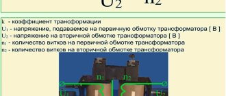
What is affected by the number of turns in a transformer?
If we talk about the secondary windings of the transformer, then the value of the number of turns in them mainly affects the output voltage. Things are more complicated with the primary winding, since the voltage on it is set by the supply network. The parameters of the primary winding affect the no-load current, and, consequently, the efficiency. When changing the parameters of the primary winding, it will be necessary to recalculate all secondary windings.
And it is worth noting that it is better not to open the secondary winding of the CT.
How to calculate the number of turns of a transformer: calculation rules for different types
If you need to independently manufacture a power supply device for electronic equipment, the question of how to independently calculate the number of turns of a transformer and how to determine the data for the wires of the primary and secondary windings is the most common question.
Correct calculation is possible if initial data on the characteristics of consumer power, input and output voltages are available. indicators of the weight and dimensions of the device may also impose restrictions.
Calculation method
The full calculation of the transformer is quite complex and takes into account the following parameters:
- supply voltage and frequency;
- number of secondary windings;
- current consumption of each secondary winding;
- type of core material;
- weight and size indicators.
At the household level, for the manufacture of devices powered by a standard 220V 50Hz network, the design can be significantly simplified.
The technique does not require special knowledge of complexity, and if you have experience, it takes little time.
The following data is required for the calculation:
- Number of exits.
- Voltage and current consumption of each winding.
The design of any transformer is based on the total power of all secondary loads:
Pс=I1∙U1+ I2∙U2+… In∙Un
To take into account losses, the concept of overall power has been introduced, for the calculation of which a simple formula is used:
P=1.25∙ Pс
Knowing the power, you can determine the core cross-section:
S=√P
The resulting cross-sectional value will be expressed in square centimeters!
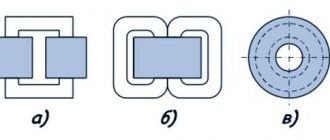
Further calculations depend on the type and material of the selected core. Magnetic cores are of the following types:
- armored;
- rod;
- O-shaped.
The methods for manufacturing magnetic cores also differ:
- typesetting - from individual plates;
- twisted, split or solid.
Armored or rod magnetic cores are usually split, while O-shaped ones are structurally made exclusively in one piece. In this respect, they are no different from continuous rod cores.
To determine the number of turns, use the following ratio, showing how many turns are needed per 1 volt of voltage:
W=K/S,
where K is a coefficient that depends on the material and type of core.
To simplify calculations, the following coefficient values are adopted:
- For stacked magnetic cores made of W- or U-shaped plates K=60.
- For split magnetic cores K=50.
- For O-shaped cores K=40.
As you can see, the shortest length of the winding wire, and therefore the best weight and size indicators, will be for O-shaped cores. In addition, designs with such cores have a small field of parasitic magnetic scattering and maximum efficiency. They are rarely used only because it is technically difficult to wind a winding around a closed core.
Knowing the parameter W, it is easy to determine the number of turns for each winding:
n=U∙W
To take into account the voltage drop on the primary winding, wound with a large amount of thin wire, the number of turns in it should be increased by 5%. This is especially true for small-sized, low-power structures.
You can reduce the no-load current by increasing the W value for each of the windings, but you should be aware that an excessive increase can lead to saturation of the magnetic circuit, which will lead to a sharp increase in the no-load current and a decrease in the output voltage.
At the final stage, the diameter of the conductors of each winding is determined. The calculation formula is as follows:
d=0.7√I
The diameter of the winding wire is determined for all windings without exception.
HOW TO CALCULATE AND MANUFACTURE A CURRENT TRANSFORMERThe resulting values are rounded to the nearest larger standard wire diameter.
Viktor Khripchenko village Oktyabrsky, Belgorod region.
While doing calculations for a powerful power supply, I ran into a problem - I needed a current transformer that would accurately measure current. There is not much literature on this topic. And on the Internet there are only requests - where to find such a calculation. I read the article [1]; Knowing that errors may be present, I dealt with this topic in detail. Errors, of course, were present: there is no matching resistor Rc (see Fig. 2) to match the output of the secondary winding of the transformer (it was not calculated) for current. The secondary circuit of the current transformer is calculated as usual for a voltage transformer (set the required voltage on the secondary winding and make the calculation).
A little theory
So, first of all, a little theory [4]. A current transformer operates as a current source with a given primary current representing the current of the protected section of the circuit. The magnitude of this current practically does not depend on the load of the secondary circuit of the current transformer, since its resistance with load, reduced to the number of turns of the primary winding, is negligible compared to the resistance of the elements of the electrical circuit. This circumstance makes the operation of a current transformer different from the operation of power transformers and voltage transformers.
In Fig. Figure 1 shows the markings of the ends of the primary and secondary windings of the current transformer, wound on the magnetic core in the same direction (I1 is the current of the primary winding, I2 is the current of the secondary winding). The current of the secondary winding I2, neglecting the small magnetizing current, is always directed so as to demagnetize the magnetic circuit.
The arrows show the direction of the currents. Therefore, if we take the upper end of the primary winding as the beginning, then the beginning of the secondary winding is also its upper end. The accepted marking rule corresponds to the same direction of currents, taking into account the sign. And the most important rule: the condition of equality of magnetic fluxes.
The algebraic sum of the products I1 x W1 - I2 x W2 = 0 (neglecting the small magnetizing current), where W1 is the number of turns of the primary winding of the current transformer, W2 is the number of turns of the secondary winding of the current transformer.
Example. Suppose you, given the primary winding current of 16 A, made a calculation and there are 5 turns in the primary winding - calculated. You specify the current of the secondary winding, for example, 0.1 A, and according to the above-mentioned formula I1 x W1 = I2 x W2, we calculate the number of turns of the secondary winding of the transformer.
W2 = I1 x W1 / I2
Next, having calculated the L2 inductance of the secondary winding, its resistance XL1, we will calculate U2 and then Rc. But that's a little later. That is, you see that having specified the current in the secondary winding of transformer I2, only then do you calculate the number of turns. The current of the secondary winding of current transformer I2 can be set to any value - from here Rc will be calculated. And -I2 should be greater than the loads that you will connect
The current transformer should only operate on a current-matched load (we are talking about Rc).
If the user requires a current transformer for use in protection circuits, then such subtleties as the direction of the windings and the accuracy of the resistive load Rc can be neglected, but this will no longer be a current transformer, but a current sensor with a large error. And this error can be eliminated only by creating a load on the device (I mean the power source where the user is going to install protection using a current transformer), and using the protection circuit to set its current response threshold. If the user requires a current measurement circuit, then these subtleties must be observed.
In Fig. Figure 2 (dots - the beginning of the windings) shows the resistor Rc, which is an integral part of the current transformer for matching the currents of the primary and secondary windings. That is, Rc sets the current in the secondary winding. It is not necessary to use a resistor as Rc, you can use an ammeter or a relay, but a mandatory condition must be met - the internal load resistance must be equal to the calculated Rc.
If the load is not matched for current, it will be a high voltage generator. Let me explain why this is so. As mentioned earlier, the current in the secondary winding of the transformer is directed in the opposite direction from the direction of the current in the primary winding. And the secondary winding of the transformer works as a demagnetizing winding. If the load in the secondary winding of the transformer is not current matched or is absent, the primary winding will act as a magnetizing winding. Induction increases sharply, causing strong heating of the magnetic wire due to increased losses in the steel. The EMF induced in the winding will be determined by the rate of flux changes over time, which has the greatest value when the trapezoidal (due to saturation of the magnetic circuit) flux passes through zero values. The inductance of the windings decreases sharply, which causes even greater heating of the transformer and ultimately its failure.
Types of magnetic cores are shown in Fig. 3 [3].
Twisted or tape magnetic circuit is the same concept, as well as the expression ring or toroidal magnetic circuit: both are found in the literature.
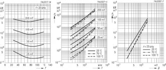
This can be a ferrite core or W-shaped transformer iron, or strip cores. Ferrite cores are usually used at higher frequencies - 400 Hz and above due to the fact that they operate in weak and medium magnetic fields (W = 0.3 Tesla maximum). And since ferrites, as a rule, have a high magnetic permeability µ and a narrow hysteresis loop, they quickly enter the saturation region. The output voltage, at f = 50 Hz, on the secondary winding is a few volts or less. As a rule, ferrite cores are marked with their magnetic properties (example M2000 means magnetic permeability of the core µ equal to 2000 units).
There is no such marking on tape magnetic cores or from W-shaped plates, and therefore their magnetic properties have to be determined experimentally, and they operate in medium and strong magnetic fields [4] (depending on the grade of electrical steel used - 1.5...2 T and more) and are used at frequencies of 50 Hz...400 Hz. Ring or toroidal twisted (tape) magnetic circuits also operate at a frequency of 5 kHz (and from permalloy even up to 25 kHz). When calculating S - the cross-sectional area of a strip toroidal magnetic circuit, it is recommended to multiply the result by a coefficient k = 0.7...0.75 for greater accuracy. This is explained by the design feature of tape magnetic cores.
What is a split magnetic strip tape (Fig. 3)? Steel tape, 0.08 mm thick or thicker, is wound on a mandrel and then annealed in air at a temperature of 400...500 ° C to improve their magnetic properties. Then these forms are cut, the edges are polished, and the magnetic circuit is assembled. Ring (continuous) twisted magnetic cores made of thin tape materials (permalloy 0.01...0.05 mm thick) are coated with electrically insulating material during winding and then annealed in a vacuum at 1000...1100 °C.
To determine the magnetic properties of such magnetic cores, it is necessary to wind 20...30 turns of wire (the more turns, the more accurate the value of the magnetic permeability of the core) on the magnetic core and measure the L-inductance of this winding (μH). Calculate S - cross-sectional area of the transformer core (mm2), lm - average length of the magnetic field line (mm). And using the formula, calculate jll - the magnetic permeability of the core [5]:
(1) µ = (800 x L x lm) / (N2 x S) - for strip and W-shaped core.
(2) µ = 2500*L(D + d) / W2 x C(D - d) - for an annular (toroidal) core.
When designing a transformer for higher currents, a large diameter wire is used in the primary winding, and here you will need a twisted core magnetic core (U-shaped), twisted ring core or ferrite toroid.
If anyone has held an industrial current transformer for high currents in their hands, they have seen that there is no primary winding wound onto the magnetic core, but there is a wide aluminum bus running through the magnetic circuit.
I reminded this then that the calculation of a current transformer can be done either by specifying W - magnetic induction in the core, while the primary winding will consist of several turns and you will have to suffer by winding these turns onto the transformer core. Or you need to calculate the magnetic induction W of the field created by a current-carrying conductor in the core.
Now let’s start calculating the current transformer, applying the laws [6].
You are set by the current of the primary winding of the current transformer, that is, the current that you will control in the circuit.
Let I1 = 20 A, the frequency at which the current transformer will operate, f = 50 Hz.
Let's take a tape ring core OJ125/40-10 or (40x25x10 mm), schematically shown in Fig. 4.
Dimensions: D = 40 mm, d = 25 mm, C = 10 mm.
Next are two calculations with detailed explanations of exactly how the current transformer is calculated, but too many formulas make it difficult to post the calculations on the site page. For this reason, the full version of the article on how to calculate a current transformer has been converted to PDF and can be downloaded using the LINK.
Site administration address
Alternative method for dimensions
The approximate parameters of the transformer, based on the available core, can be determined in another way, and then conclusions can be drawn about the possibility of further use.
Knowing the cross-sectional area of the magnetic circuit in square centimeters, you can estimate the maximum power that this converter is capable of providing:
PG=S2
It should be borne in mind that this power is dimensional, and the real one will have a smaller value:
P=0.8 PG
Usually, provided that the calculated power matches the required one, the primary winding connected to the 220 V network can be left untouched, recalculating only the parameters at the outputs.
Examples of real calculations
As an example, let's calculate the power transformer for the charger. Initial data:
- mains voltage – 220V;
- output voltage – 14V;
- secondary winding current – 10A;
Using the output parameters, we determine the power of the secondary winding: P=14∙10=140 W
Overall power: P=1.25∙140=175 W.
The cross-sectional area of the core magnetic circuit will be: S=√175=13.3 cm 2
The best parameters are found in designs in which the core cross-section is close to square. Thus, we select a strip armored wire with a core size of 3.5x4 cm. Its area is 14 cm 2.
For a given core K=50. Thus: W=50/14=3.6 vit/volt
For windings, the total number of turns is equal to:
- primary winding n1=220∙3.6= 792 turns;
- secondary winding n2=14∙3.6=50 turns.
Since the transformer is powerful, the voltage drop on the primary winding can be ignored.
We determine the diameter of the winding wires: d2=0.7√10=2.2 mm.
The closest standard value is 2.4 mm.
To find the diameter of the primary winding wire, let's find the current through it: I=P/U=175/220=0.8A.
This current corresponds to the diameter: d1=0.7√0.8=0.63 mm.
The nearest standard value has just such a value.
A more in-depth calculation involves estimating the fill factor of the free window of the magnetic circuit. A large number of secondary windings may not fit in the free window, then it will be necessary to choose a more powerful core. If the windings are placed too loosely, the efficiency of the device deteriorates and the magnetic dissipation field increases. However, as practice shows, with the correct choice of core cross-section, such calculations become unnecessary.
Using a Multimeter
Using a multimeter, you can find data for recalculating the windings of an existing transformer. To do this, you need to make an additional coil from any available wire. After connecting the device to the network, it is necessary to measure the voltage on the additional coil. Now you can easily calculate the required number of turns per volt and recalculate the transformer to meet the required requirements.
Laboratory work in physics on the topic “Determination of the number of turns in the windings of a transformer.”
“creative work with children from 3 to 10 years old”
11th grade Laboratory workshop.
Laboratory work No. 4. Topic: “Determination of the number of turns in the windings of a transformer.” Purpose of the work:
determine the number of turns in the transformer winding.
Equipment:
laboratory transformer;
AC voltage source 12V; Avometer AVO-63; insulated wire. Progress.
Brief theoretical information. To determine the number of turns in the winding of a transformer with unknown parameters, you can use the property of the transformer that in no-load mode the ratio of voltages on the primary U 1 and secondary U 2 windings is equal to the ratio of the number of turns N 1 in the primary winding to the number of turns N 2 in the secondary winding :
By winding a secondary winding with a known number of turns N 2 around the transformer core and measuring the voltage U 2 on the primary winding, you can determine the number of turns N 1 in the primary winding: N 1 = N 2.
1. Wind a secondary winding of 20-40 turns onto the core of the transformer under study. 2. Connect the terminals of the primary winding of the transformer to an alternating voltage source U 1 = 12V, measure the voltage on the secondary winding. 3. Based on the measured voltage values and the known number of turns in the secondary winding, determine the number of turns in the primary winding. 4. Write the results of measurements and calculations in the table:
Source: infourok.ru
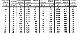
Table of volts per turn
In order not to constantly carry out calculations, you can use the table, which shows the average data of the windings depending on the power:
| Power, P | Section in cm2, S | Number of vit. /B, W | Power, P | Section in cm2, S | Number of vit. /B, W |
| 1 | 1.4 | 32 | 50 | 9.0 | 5.0 |
| 2 | 2.1 | 21 | 60 | 9.8 | 4.6 |
| 5 | 3.6 | 13 | 70 | 10.3 | 4.3 |
| 10 | 4.6 | 9.8 | 80 | 11.0 | 4.1 |
| 15 | 5.5 | 8.4 | 90 | 11.7 | 3.9 |
| 20 | 6.2 | 7.3 | 100 | 12.3 | 3.7 |
| 25 | 6.6 | 6.7 | 120 | 13.4 | 3.4 |
| 30 | 7.3 | 6.2 | 150 | 15.0 | 3.0 |
| 40 | 8.3 | 5.4 | 200 | 17.3 | 2.6 |
How to measure wire diameter
If you have a micrometer lying around at home, you can use it to measure the diameter of the wire.
It is better to first heat the wire in a match flame and only then remove the weakened insulation with a scalpel. If this is not done, then part of the copper can be removed along with the insulation, which will reduce the accuracy of the measurement, especially for a thin wire.
If you don’t have a micrometer, you can use an ordinary ruler. You need to wind 100 turns of wire around the tip of a screwdriver or another suitable axis, compress the turns with your fingernail and attach the resulting set to a ruler. Dividing the result by 100, we get the diameter of the wire with insulation. You can find out the diameter of the copper wire from the table below.
Example.
I wound 100 turns of wire and got a set length of -39 mm.
39 / 100 = 0.39 mm
Using the table, I determine the diameter of the copper wire - 0.35 mm.
Winding Wire Data Table
| Diameter without insulation, mm | Copper cross section, mm² | Resistance 1m at 20ºС, Ohm | Permissible load at current density 2A/mm² | Diameter with insulation, mm | Weight 100m with insulation, g |
| 0,03 | 0,0007 | 24,704 | 0,0014 | 0,045 | 0,8 |
| 0,04 | 0,0013 | 13,92 | 0,0026 | 0,055 | 1,3 |
| 0,05 | 0,002 | 9,29 | 0,004 | 0,065 | 1,9 |
| 0,06 | 0,0028 | 6,44 | 0,0057 | 0,075 | 2,7 |
| 0,07 | 0,0039 | 4,73 | 0,0077 | 0,085 | 3,6 |
| 0,08 | 0,005 | 3,63 | 0,0101 | 0,095 | 4,7 |
| 0,09 | 0,0064 | 2,86 | 0,0127 | 0,105 | 5,9 |
| 0,1 | 0,0079 | 2,23 | 0,0157 | 0,12 | 7,3 |
| 0,11 | 0,0095 | 1,85 | 0,019 | 0,13 | 8,8 |
| 0,12 | 0,0113 | 1,55 | 0,0226 | 0,14 | 10,4 |
| 0,13 | 0,0133 | 1,32 | 0,0266 | 0,15 | 12,2 |
| 0,14 | 0,0154 | 1,14 | 0,0308 | 0,16 | 14,1 |
| 0,15 | 0,0177 | 0,99 | 0,0354 | 0,17 | 16,2 |
| 0,16 | 0,0201 | 0,873 | 0,0402 | 0,18 | 18,4 |
| 0,17 | 0,0227 | 0,773 | 0,0454 | 0,19 | 20,8 |
| 0,18 | 0,0255 | 0,688 | 0,051 | 0,2 | 23,3 |
| 0,19 | 0,0284 | 0,618 | 0,0568 | 0,21 | 25,9 |
| 0,2 | 0,0314 | 0,558 | 0,0628 | 0,225 | 28,7 |
| 0,21 | 0,0346 | 0,507 | 0,0692 | 0,235 | 31,6 |
| 0,23 | 0,0416 | 0,423 | 0,0832 | 0,255 | 37,8 |
| 0,25 | 0,0491 | 0,357 | 0,0982 | 0,275 | 44,6 |
| 0,27 | 0,0573 | 0,306 | 0,115 | 0,31 | 52,2 |
| 0,29 | 0,0661 | 0.2bb | 0,132 | 0,33 | 60,1 |
| 0,31 | 0,0755 | 0,233 | 0,151 | 0,35 | 68,9 |
| 0,33 | 0,0855 | 0,205 | 0,171 | 0,37 | 78 |
| 0,35 | 0,0962 | 0,182 | 0,192 | 0,39 | 87,6 |
| 0,38 | 0,1134 | 0,155 | 0,226 | 0,42 | 103 |
| 0,41 | 0,132 | 0,133 | 0,264 | 0,45 | 120 |
| 0,44 | 0,1521 | 0,115 | 0,304 | 0,49 | 138 |
| 0,47 | 0,1735 | 0,101 | 0,346 | 0,52 | 157 |
| 0,49 | 0,1885 | 0,0931 | 0,378 | 0,54 | 171 |
| 0,51 | 0,2043 | 0,0859 | 0,408 | 0,56 | 185 |
| 0,53 | 0,2206 | 0,0795 | 0,441 | 0,58 | 200 |
| 0,55 | 0,2376 | 0,0737 | 0,476 | 0,6 | 216 |
| 0,57 | 0,2552 | 0,0687 | 0,51 | 0,62 | 230 |
| 0,59 | 0,2734 | 0,0641 | 0,547 | 0,64 | 248 |
| 0,62 | 0,3019 | 0,058 | 0,604 | 0,67 | 273 |
| 0,64 | 0,3217 | 0,0545 | 0,644 | 0,69 | 291 |
| 0,67 | 0,3526 | 0,0497 | 0,705 | 0,72 | 319 |
| 0,69 | 0,3739 | 0,0469 | 0,748 | 0,74 | 338 |
| 0,72 | 0,4072 | 0,043 | 0,814 | 0,78 | 367 |
| 0,74 | 0,4301 | 0,0407 | 0,86 | 0,8 | 390 |
| 0,77 | 0,4657 | 0,0376 | 0,93 | 0,83 | 421 |
| 0,8 | 0,5027 | 0,0348 | 1,005 | 0,86 | 455 |
| 0,83 | 0,5411 | 0,0324 | 1,082 | 0,89 | 489 |
| 0.86 | 0,5809 | 0,0301 | 1,16 | 0,92 | 525 |
| 0,9 | 0,6362 | 0,0275 | 1,27 | 0,96 | 574 |
| 0,93 | 0,6793 | 0,0258 | 1,36 | 0,99 | 613 |
| 0,96 | 0,7238 | 0,0242 | 1,45 | 1,02 | 653 |
| 1 | 0,7854 | 0,0224 | 1,57 | 1,07 | 710 |
| 1,04 | 0,8495 | 0,0206 | 1,7 | 1,12 | 764 |
| 1,08 | 0,9161 | 0,0191 | 1,83 | 1,16 | 827 |
| 1,12 | 0,9852 | 0,0178 | 1,97 | 1,2 | 886 |
| 1,16 | 1,057 | 0,0166 | 2,114 | 1,24 | 953 |
| 1,2 | 1,131 | 0,0155 | 2,26 | 1,28 | 1020 |
| 1,25 | 1,227 | 0,0143 | 2,45 | 1,33 | 1110 |
| 1,3 | 1,327 | 0,0132 | 2,654 | 1,38 | 1190 |
| 1,35 | 1,431 | 0,0123 | 2,86 | 1,43 | 1290 |
| 1,4 | 1,539 | 0,0113 | 3,078 | 1,48 | 1390 |
| 1,45 | 1,651 | 0,0106 | 3,3 | 1,53 | 1490 |
| 1,5 | 1,767 | 0,0098 | 3,534 | 1,58 | 1590 |
| 1,56 | 1,911 | 0,0092 | 3,822 | 1,64 | 1720 |
| 1,62 | 2,061 | 0,0085 | 4,122 | 1,71 | 1850 |
| 1,68 | 2,217 | 0,0079 | 4,433 | 1,77 | 1990 |
| 1,74 | 2,378 | 0,0074 | 4,756 | 1,83 | 2140 |
| 1,81 | 2,573 | 0,0068 | 5,146 | 1,9 | 2310 |
| 1,88 | 2,777 | 0,0063 | 5,555 | 1,97 | 2490 |
| 1,95 | 2,987 | 0,0059 | 5,98 | 2,04 | 2680 |
| 2,02 | 3,205 | 0,0055 | 6,409 | 2,12 | 2890 |
| 2,1 | 3,464 | 0,0051 | 6,92 | 2,2 | 3110 |
| 2,26 | 4,012 | 0,0044 | 8,023 | 2,36 | 3620 |
| 2,44 | 4,676 | 0,0037 | 9,352 | 2,54 | 4220 |