Example
As an example, let's calculate the power transformer for the charger.
Initial data:
- mains voltage – 220V;
- output voltage – 14V;
- secondary winding current – 10A;
Determine the power of the secondary winding
Using the output parameters, we determine the power of the secondary winding:
P=14∙10= 140 W
Determine the overall capacity of the pipeline
Overall power:
P=1.25∙140= 175 W.
Finding the cross-sectional area of the core magnetic circuit
The cross-sectional area of the core magnetic circuit will be:
S=√175= 13.3 cm2
The best parameters are found in designs in which the core cross-section is close to square.
Thus, we select a strip armored wire with a core size of 3.5x4 cm. Its area is 14 cm2.
For a given core K=50.
To determine the number of turns, use the following ratio, showing how many turns are needed per 1 volt of voltage:
W=K/S,
where K is a coefficient that depends on the material and type of core.
To simplify calculations, the following coefficient values are adopted:
- For stacked magnetic cores made of W- or U-shaped plates K=60.
- For split magnetic cores K=50.
- For O-shaped cores K=40.
Thus: W=50/14=3.6 vit/volt
For windings, the total number of turns is equal to:
- primary winding n1=220∙3.6= 792 turns;
- secondary winding n2=14∙3.6=50 turns.
Since the transformer is powerful, the voltage drop on the primary winding can be ignored.
Determine the diameter of the secondary winding wires
d=0.7√I (secondary winding current)
We determine the diameter of the winding wires: d2=0.7√10=2.2 mm.
The closest standard value is 2.4 mm.
Calculation method
The full calculation of the transformer is quite complex and takes into account the following parameters:
- supply voltage and frequency;
- number of secondary windings;
- current consumption of each secondary winding;
- type of core material;
- weight and size indicators.
At the household level, for the manufacture of devices powered by a standard 220V 50Hz network, the design can be significantly simplified.
The technique does not require special knowledge of complexity, and if you have experience, it takes little time.
The following data is required for the calculation:
- Number of exits.
- Voltage and current consumption of each winding.
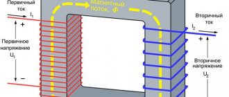
The design of any transformer is based on the total power of all secondary loads:
Pс=I1∙U1+ I2∙U2+… In∙Un
To take into account losses, the concept of overall power has been introduced, for the calculation of which a simple formula is used:
P=1.25∙ Pс
Knowing the power, you can determine the core cross-section:
S=√P
The resulting cross-sectional value will be expressed in square centimeters!
Further calculations depend on the type and material of the selected core. Magnetic cores are of the following types:
- armored;
- rod;
- O-shaped.
The methods for manufacturing magnetic cores also differ:
- typesetting - from individual plates;
- twisted, split or solid.
Armored or rod magnetic cores are usually split, while O-shaped ones are structurally made exclusively in one piece. In this respect, they are no different from continuous rod cores.
To determine the number of turns, use the following ratio, showing how many turns are needed per 1 volt of voltage:
W=K/S,
where K is a coefficient that depends on the material and type of core.
To simplify calculations, the following coefficient values are adopted:
- For stacked magnetic cores made of W- or U-shaped plates K=60.
- For split magnetic cores K=50.
- For O-shaped cores K=40.
As you can see, the shortest length of the winding wire, and therefore the best weight and size indicators, will be for O-shaped cores. In addition, designs with such cores have a small field of parasitic magnetic scattering and maximum efficiency. They are rarely used only because it is technically difficult to wind a winding around a closed core.
Knowing the parameter W, it is easy to determine the number of turns for each winding:
n=U∙W
To take into account the voltage drop on the primary winding, wound with a large amount of thin wire, the number of turns in it should be increased by 5%. This is especially true for small-sized, low-power structures.
You can reduce the no-load current by increasing the W value for each of the windings, but you should be aware that an excessive increase can lead to saturation of the magnetic circuit, which will lead to a sharp increase in the no-load current and a decrease in the output voltage.
At the final stage, the diameter of the conductors of each winding is determined. The calculation formula is as follows:
d=0.7√I
The diameter of the winding wire is determined for all windings without exception.
The resulting values are rounded to the nearest larger standard wire diameter.
Inductive reactance - how to find it
A real coil has not only reactive, but also ordinary resistance. Inductive reactance is determined by the formula:
XL=2*P*v*L
The following notations are used here:
- XL is the value under consideration.
- The symbol “P” represents the number Pi.
- V represents frequency.
- L is a designation for the amount of inductance.
It should be noted that the value (2*P*v) represents a circular frequency, which is denoted by the Greek symbol “omega”.
Coils with different cores
The quantity under consideration obeys Ohm's law. The formula looks like this:
I=U/XL
I, U represent current and voltage, XL is inductive reactance.
Coil magnetic field configuration
To determine the required value, you can use the given formulas. You can use an ammeter and a voltmeter. The first of them must be connected in series, the second in parallel.
The following must be taken into account. In fact, in a circuit in which inductance is connected, there are two types of resistance: active and reactive. By measuring current and voltage, you can determine their resulting value. It must be remembered that it is not their simple sum.
The fact is that in an alternating circuit, where there is only a coil and no capacitor, the voltage is ahead of the current by a quarter of the oscillation period. This value is equal to 90 degrees.
The impedance is determined as follows. To do this, you need to draw a corresponding diagram. If you plot the normal value horizontally, and the reactive value vertically, and then build a rectangle using these vectors, then the length of its diagonal will be equal to the full value.
Magnetic field of a wire
For example, if you select the elements of the circuit in such a way that both of these values are equal in absolute value, then the required part will be determined as their total value multiplied by the square root of two.
In order to obtain information about the dependence of inductive reactance on frequency, you can use an oscilloscope.
When using alternating current, it is necessary to take into account not only ordinary, but also inductive reactance. It occurs if there is a coil in the electrical circuit.
Device Description
The inductor can be helical, helical or helical, having a coiled insulated conductor, which has a significant inductance value with a small capacitance with active resistance. As a consequence, the current flows through the current source with significant inertia.
Main component of an electrical circuit
Note! Used to suppress interference, smooth out beats, store energy, limit alternating current or resonant/frequency selective circuit circuits.
It is worth pointing out that its applications are varied. It is called a throttle, variometer, solenoid and current-limiting reactor. However, the main technical characteristics vary. They may differ in current strength, loss resistance, quality factor, capacitance and temperature quality factor.
Full definition from physics
Calculation of inductance coils: online calculator
Five-band equalizer on KA22234
The figure shows a diagram of a two-channel five-band equalizer on the KA22234 microcircuit (analogous to BA3822L). Regulation frequencies: 100, 300, 1000, 3000, 10000 Hz. Main characteristics of the equalizer: Minimum supply voltage 3.5 V. Maximum supply voltage 14 V Quiescent current 7 mA Frequency range from 20 Hz to 20 kHz Input impedance 16K THD no more than 0.1% Maximum ...Read more.
This motion sensor can detect a moving person at a distance of 1 meter. The HOA1405 IR module is used as a sensor. When the sensor detects reflected infrared radiation, an alarm will sound for 2 minutes. The circuit can be modified for different applications. For given values of R4 and C2, the playing time...More details.
Expert opinion
It-Technology, Electrical power and electronics specialist
Ask questions to the “Specialist for modernization of energy generation systems”
How to determine the inductance of a coil formula - Yacht Club Ost-West Note that the ratio pd is always greater than one, since the thickness of the wire insulation is finite, and the minimum possible distance between two adjacent turns with very thin insulation, located without a gap, is equal to the diameter of the wire d. Ask, I'm in touch!
The phenomenon of self-induction - definition, formulas, examples
- — The master oscillator is made on VT1. Through C4, the RF signal is supplied to the input of the power amplifier at VT2. The collector circuit VT2 includes a matching device in the form of a double U-shaped filter C8L4C11C12L5C14, designed to ensure optimal communication between the radio transmitter and the antenna. L6 -. — The master oscillator is made on VT1 (K342A), the frequency is stabilized square. resonator. The pre-final amplifier uses VT2 type KT603B. Modulation is carried out using transistor VT4 with pulses of positive polarity from a multivibrator or other signal source. Output stage. — The receiver can be tuned in the range of 70.150 MHz without changing the values of the tuning elements. The real sensitivity of the receiver is about 0.3 µV, the supply voltage is 9 V. It should be noted that the supply voltage of the MC3362 is 2.7 V, and the MC34119 is 2.12 V, so the MC3362 is powered through. — The inductance of the coil depends on its geometric dimensions, the number of turns and the method of winding. The larger the diameter, winding length and number of turns, the greater the inductance. If the turns of a coil are wound tightly, its inductance will be greater than a coil wound loosely. Rewind if necessary. — This amplifier provides gain depending on frequency - 18 (50 MHz) to 14 (230 MHz) dB. It uses a low-noise field-effect transistor, which ensures high sensitivity. The input circuit is formed by inductance L1 and the capacitances of varicaps, diodes and a transistor, providing frequency.
Useful tips Connection diagrams Principles of operation of devices Main concepts Meters from Energomer Precautions Incandescent lamps Video instructions for the master Testing with a multimeter
Factors affecting induction
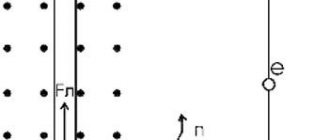
Induction is influenced by the number of conductor turns, cross-sectional area, length and materials. Due to the increase in turns, the induction increases and vice versa. As for the cross section, the larger the source, the greater the indicator. Also, the greater the magnetic type of permeability, the greater the inductive indicator.
Factors affecting the conversion of energy into a magnetic field