4.5
Average rating: 4.5
Total ratings received: 60.
4.5
Average rating: 4.5
Total ratings received: 60.
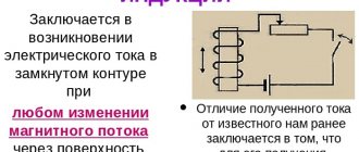
An induced emf occurs in a circuit when the magnetic flux through it changes. A rarer case of magnetic induction is the movement of a solitary conductor in a magnetic field. Let us briefly consider the induced emf in moving conductors.
Induction mechanism in a moving conductor
From the physics course in the 11th grade we know that electric current is the movement of charge carriers. If the magnetic flux through the circuit changes, then a vortex electric field appears in the circuit, due to which the carriers move and an electric current arises. However, this is not the only way to create movement of charges in a conductor.
The second way to create moving charges in a conductor is to use the Lorentz force. If this force begins to act on charge carriers in the conductor, then an emf and an electric current will arise in it.
Rice. 1. Lorentz force.
The Lorentz force acts only on moving charges. Consequently, if a conductor in which there are charge carriers begins to move in a magnetic field, then a force will begin to act on the charges, and they will begin to move - an emf will arise in the conductor.
Note that the EMF arising in this case in the conductor has a different cause than the change in magnetic flux through the circuit. If, when the flow changes, the cause of the emf is a vortex electric field, then in a moving conductor the cause of the emf is the Lorentz force.
Designation and units of measurement
In the SI system of units, inductance is measured in henry, abbreviated Hn, in the CGS system - in centimeters (1 Hn = 10 9 cm). A circuit has an inductance of one henry if, when the current changes by one ampere per second, a voltage of one volt appears at the terminals of the circuit. A real, non-superconducting circuit has an ohmic resistance R, so an additional voltage U=I*R will appear on it, where I is the current flowing through the circuit at a given instant of time.
The symbol used to denote inductance was taken in honor of Lenz Emil Christianovich (Heinrich Friedrich Emil Lenz)
. The unit of inductance is named after Joseph Henry [8]. The term inductance itself was coined by Oliver Heaviside in February 1886.
An electric current that flows in a closed circuit creates a magnetic field around itself, the induction of which, according to the Biot-Savart-Laplace law, is proportional to the current. The magnetic flux Ф associated with the circuit is therefore directly proportional to the current I in the circuit: where the proportionality coefficient L is called the inductance of the circuit. When the current strength changes in the circuit, the magnetic flux associated with it will also change; This means that an emf will be induced in the circuit. Emergence of e.m.f. Induction in a conductive circuit when the current strength changes in it is called self-induction. From the expression, the unit of inductance henry (H) is specified: 1 H is the inductance of a circuit whose magnetic self-induction flux at a current of 1 A is equal to 1 Wb: 1 H = 1 Wb/s = 1 V
Let's calculate the inductance of an infinitely long solenoid. The total magnetic flux through the solenoid (flux linkage) is equal to μμ(N 2 I/l)S. Substituting in, we find that the inductance of the solenoid depends on the length l of the solenoid, the number of its turns N, its area S and the magnetic permeability μ of the substance from which the solenoid core is made. It has been proven that the inductance of a circuit depends, in the general case, only on the geometric shape of the circuit, its dimensions and the magnetic permeability of the medium in which it is located, and it is possible to draw an analogue of the inductance of a circuit with the electrical capacitance of a solitary conductor, which also depends only on the shape of the conductor, its dimensions and dielectric constant of the medium. Let us find, applying Faraday’s law to the phenomenon of self-induction, that the emf. self-induction is equal to If the circuit does not undergo deformation and the magnetic permeability of the medium remains unchanged (later it will be shown that the last condition is not always met), then L = const and (3) where the minus sign, determined by Lenz’s rule, indicates that the presence of inductance in circuit leads to a slowdown in the change in current in it. If the current increases over time, then (dI/dt 0 i.e. the self-induction current is directed towards the current caused by the external source and slows down its increase. If the current decreases over time, then (dI/dt>0) and ξs >1) , having high inductance, emf. self-induction can be many times higher than the emf. current source included in the circuit. Thus, it is necessary to take into account that a circuit containing inductance cannot be abruptly opened, since this (the occurrence of significant self-induction emf) can lead to insulation breakdown and failure of measuring instruments. If resistance is gradually introduced into the circuit, then the emf. self-induction will not reach large values.
It will be interesting➡ VVGNG cable: design, markings, main characteristics
The phenomenon of mutual induction. Transformer.
Let's consider two stationary contours that are located quite close to each other. If a current flows in circuit 1, then the magnetic flux that is created by this current (the field that creates this flux is shown in the figure with solid lines) is directly proportional to I1. Let us denote by F21 the part of the flow that penetrates circuit 2. Then where L21 is the proportionality coefficient.
If the current I1 changes its value, then an emf is induced in circuit 2. ξi2, which, according to Faraday’s law, will be equal and opposite in sign to the rate of change of the magnetic flux Ф21, which is created by the current in the first circuit and penetrates the second: Similarly, when current I2 flows in circuit 2, the magnetic flux penetrates the first circuit. If F12 is part of this flow that penetrates circuit 1, then if the current I2 changes its value, then an emf is induced in circuit 1. ξi1, which is equal and opposite in sign to the rate of change of magnetic flux Ф12, which is created by the current in the second circuit and penetrates the first: The phenomenon of emf occurrence. in one of the circuits when the current strength in the other changes is called mutual induction. Proportionality coefficients L21 and L12 are called mutual inductance of the circuits. Calculations, which are confirmed by experience, show that L21 and L12 are equal to each other, i.e. The proportionality coefficients L12 and L21 depend on the size, geometric shape, relative position of the circuits and on the magnetic permeability of the medium surrounding the circuits. The unit of mutual inductance is the same as for inductance, henry (H). Let's find the mutual inductance of two coils that are wound on a common toroidal core. This case is of great practical importance. The magnetic induction of the field, which is created by the first coil with the number of turns N1, current I1 and magnetic permeability μ of the core, B = μμ(N1I1/l) where l is the length of the core along the center line. Magnetic flux through one turn of the second coil Ф2 = BS = μμ(N1I1/l)S
This means that the total magnetic flux (flux linkage) through the secondary winding, which contains N2 turns, Flux Ψ is created by the current I1, therefore, using, we find If we calculate the magnetic flux that is created by coil 2 through coil 1, then for L12 we obtain the expression in accordance with the formula . This means that the mutual inductance of two coils that are wound on a common toroidal core. A transformer (from the Latin transformo - to transform) is a static electromagnetic device that has two or more inductively coupled windings on any magnetic circuit and is designed to convert through electromagnetic induction of one or more AC systems (voltages) to one or more other AC systems (voltages) without changing the frequency of the AC system (voltages)
Induction emf in a moving conductor
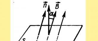
Let us calculate the induced emf in a conductor of length $l$, which moves at a constant speed $v$ so that the magnetic induction vector $\overrightarrow B$ of a uniform field is perpendicular to the conductor and directed at an angle $\alpha$ to the speed of movement of the conductor.
According to the Lorentz force formula, its magnitude is equal to:
$$F=|q|Bvsin\alpha$$
The component of this force directed along the conductor does positive work, which on the path $l$ is equal to:
$$A=Fl=|q|Bvlsin\alpha$$
Note that the second component of the Lorentz force performs negative work of equal magnitude. Therefore, the total work done by the Lorentz force is zero.
EMF, by definition, is equal to the ratio of the work done by the field to transfer a charge to the magnitude of this charge. Hence:
$$\mathscr{E} = {A\over q}=Bvlsin\alpha$$
Rice. 2. Movement of a conductor in a magnetic field.
Movement of a circuit in a magnetic field
The formula for induced emf in moving conductors can be applied to a rectangular circuit, dividing it into four elementary conductors (according to the number of sides). In this case, the EMF arising in opposite sides of the circuit will be directed in opposite directions. As a result, the total EMF in the circuit will be equal to zero. Consequently, when a circuit moves in a uniform magnetic field, a current cannot arise in it.
The same conclusion can be drawn from the law of electromagnetic induction. If the circuit moves in a uniform magnetic field, then the magnetic flux penetrating it does not change, therefore, the induced emf arising in it is equal to zero.
The only way to create an EMF in a circuit moving in a uniform magnetic field is to rotate it in such a way that the EMF arises due to a change in the $sin\alpha$ component. Indeed, such a rotation will change the magnetic flux through the circuit, which means that an induced emf will arise in it.
Rice. 3. Rotation of the frame in a magnetic field.
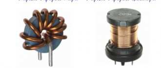
Influence of the number of turns and winding method
An inductor is a spiral made of conductive material. The operating parameters of the products will depend on the design features. Inductance is increased:
- a large number of turns per unit length;
- enlargement of the cross section;
- installation in the central part of the core with ferromagnetic characteristics.
What does the inductance of the coil depend on, examples of typical solutions
Single-turn inductance and coil inductance
To calculate an elementary structure, the converted first formula is suitable:
Ф = L * I.
If a coil is considered, this expression is transformed into the total expression of the magnetic fluxes (Ψ) generated by the individual turns:
Ψ = n * F.
The same way:
Ln = L1 * n.
In fact, for accurate calculations, differences in force lines in the central part and at the edges of the structure are taken into account. More complex expressions are used for correction.
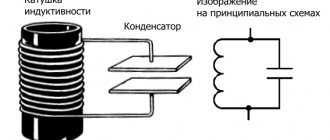
Solenoid inductance
A sufficiently long electric coil forms parallel lines of force inside. To create a uniform distribution of energy, it is necessary to use a conductor with a thickness much smaller compared to the cross-sectional diameter. Of course, it is necessary to set the same distance between the individual turns.
This design is called a solenoid. The magnetic flux density (B) in the central working part will depend in direct proportion to the length (l) and the following parameters:
- number of turns (N);
- current (i);
- winding density (n – number of circuits per unit length);
- cross-sectional area (S);
- volume (V = S * l).
Below are the basic formulas for calculations in the absence of a core, taking into account the magnetic constant (m ≈ 1.257 * 10-6 H/m):
- B = m0 * N * (i/l) = m0 * n * I;
- Ψ = m0 * N2 * (I * S/l) = m0 * n2 * i *V;
- L = m0 * N2 * (S/l) = m0 * n2 * V.
Inductance of a toroidal coil (ring-core coil)
To calculate the induction of a coil with a core, a correction factor “m” is added to the above formulas. Taking into account the special shape of the product, the following changes must be made:
L = N2 * ((m0 * m * S)/2π * rL), or L = N2 * ((m0 * m * h)/2π) * ln(R/r),
Where:
- 2π * rL – length of the working element with an average radius rL;
- R (r) and h are the outer (inner) radius and height of the torus, respectively.
The coefficient “m” takes into account the relative magnetic permeability of a certain material to the value for a neutral environment (vacuum). If m is much greater than unity, it is possible to ignore the field distortions created by a thick conductor.