A homogeneous magnetic field (MF), existing in a certain volume, is called so because it is the same at all its points. If we consider a certain plane located at right angles to the magnetic field lines, then the number of lines piercing it can be calculated. The magnetic induction flux, the formula of which was derived by the German physicist Wilhelm Weber, is the desired quantity.
Magnetic flux
What is magnetic flux
Conducting experiments and working in the field of magnetic phenomena, Weber gave a definition of magnetic flux. He characterized it as a measure of the strength and extent of the MP. This is one of the physical quantities that can be found by knowing the magnitude of the magnetic induction vector B→ (VMI). You also need to know the area of the intersecting surface and the sine of the angle between the VMI and the normal to the plane.
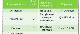
Units
Magnetic flux is denoted by the letter Φ and is measured in webers (Wb). The unit is named after the scientist's name. Thus, 1 Wb characterizes the magnetic flux Φ created by a magnetic field with an induction of one Tesla (1 T), penetrating a plane with an area of one square meter (1 m²), taking into account the fact that this surface is located at right angles to the VMI (V →).
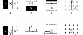
MI vector direction
The direction of magnetic fields can be indicated by a magnet arrow placed in these fields. It will spin until it stops. The northern end of the arrow will show where B→ the unit vector of a particular field is oriented.
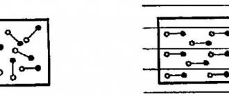
Magnetic induction lines
The frame with current behaves in the same way, having the ability to navigate the MP without interference. The direction of the induction vector indicates the orientation of the normal to such a closed electromagnetic circuit.
Attention! The rule of the gimlet (right screw) is used here. If the screw is rotated in the direction of the current in the frame, then the forward movement of the screw will coincide with the direction of the positive normal.
In some cases, the right-hand rule is used to find direction.
Visual display of MI lines
The line to which a tangent can be drawn, coinciding with B→, is called the magnetic induction (MI) line. Using such lines, you can visually display the magnetic field. These are closed contour lines that cover currents. Their density is always proportional to the value of B→ at a specific point in the MP.
Information. When dealing with the magnetic field of direct motion of charged particles, these lines are depicted as concentric circles. They have their center located in a straight line with the current, and are located in planes located at right angles to it.
The direction of magnetic lines can also be determined using the gimlet rule.
Measuring instruments
Magnetic field induction
Magnetic fluxes, determined using special instruments - fluxmeters, are measured both in laboratory and field conditions. The devices are also called webermeters. A feature of such a measuring apparatus of a magnetoelectric system (MES) is that the current is supplied to a moving frameless frame through spirals that do not have a counter moment (momentless).
Attention! At the moment when there is no current, the instrument pointer does not have a fixed position within the scale.
Scheme of application and device of a flux meter
The device consists of the following parts, marked in Fig. higher:
- permanent magnet under test – 1;
- measuring frame – 2;
- device frame – 3;
- device magnet – 4;
- correction device frame – 5;
- adjustment head for the correction frame – 6;
- switch “work - correction” – 7.
A flux meter cannot measure weak MFs due to low sensitivity.
Physical meaning of magnetic induction
Physically, this phenomenon is explained as follows. The metal has a crystalline structure (the coil is made of metal). The crystal lattice of a metal contains electrical charges - electrons. If no magnetic influence is exerted on the metal, then the charges (electrons) are at rest and do not move anywhere.
Dmitry Petrovich VasilievProfessor of Electrical Engineering, St. Petersburg State Polytechnic University If the metal comes under the influence of an alternating magnetic field (due to the movement of a permanent magnet inside the coil - namely movement), then the charges begin to move under the influence of this magnetic field.
As a result, an electric current arises in the metal. The strength of this current depends on the physical properties of the magnet and coil and the speed of movement of one relative to the other.
When a metal coil is placed in a magnetic field, the charged particles of the metal lattice (in the coil) are rotated at a certain angle and placed along the magnetic field lines.
The higher the strength of the magnetic field, the more particles rotate and the more uniform their arrangement will be.
Magnetic fields oriented in one direction do not neutralize each other, but add up, forming a single field.
Gauss's theorem for magnetic induction
What is the source of the magnetic field
The great German scientist Carl Gauss, who distinguished himself in mathematics, physics and astronomy, derived a law (theorem) in the field of magnetism. He proved that, unlike the electric field created by electric charges, the magnetic field is not created by magnetic charges. They simply do not exist in classical electrodynamics.
Information. The theorem that Gauss derived belongs to the main laws of electrodynamics and is part of Maxwell's system of equations. It describes the relationship between the flow of electric field intensity penetrating a closed arbitrary surface and the sum of charges placed in the volume outlined by this surface. The sum is expressed in algebraic form.
In relation to magnetic induction, the flux B→ passing through the closed surface S has a zero value.
Magnetic induction vector flux
Magnetic field energy
Electricity, nuclear energy, kinetic energy. Magnetic energy is a form of energy. In physical problems, most often it is necessary to calculate the energy of the magnetic field of a coil. The magnetic energy of a coil with current I and inductance L is equal to:
Volumetric field energy density:
Of course, these are not all the basic formulas of the “electricity and magnetism” section of physics, but they can often help in solving standard problems and calculations. If you come across a problem with an asterisk, and you just can’t find the key to it, make your life easier and contact the student help service for a solution.
Magnetic flux quantization
In 1961, it was practically established that if a magnetic flux is directed through a looped superconductor through which electricity flows, then the value of Φ will be a multiple of the flux quantum Φ0 = h/2e = 2.067833758*10-15 Wb. This is the SI value.
Magnetic induction vector: formula
This experiment was carried out by the Americans Deaver and Fairbank. They performed quantization using a hollow tube, passing circular currents of a superconducting nature through it. Their result of quantum dimension was two times smaller. This was due to the fact that electrons in a superconducting situation split into pairs. The particles formed twos with a charge of 2e. It is the movement of these pairs that constitutes the nature of superconducting current.
For your information. Superconductors are materials whose resistance drops sharply when the temperature drops to a certain value. It is practically equal to zero, then we can talk about superconducting properties. Metals that are excellent conductors - gold, silver, platinum - do not acquire superconducting abilities under such conditions.
Magnetic flux quantization
Lorentz force
We found out that the field acts on a current-carrying conductor. But if this is so, then initially it acts separately on each moving charge. The force with which a magnetic field acts on an electric charge moving in it is called the Lorentz force . What is important here is that the magnetic field does not act on stationary charges.
So, a particle with charge q moves in a magnetic field with induction B at speed v , and alpha is the angle between the particle velocity vector and the magnetic induction vector. Then the force that acts on the particle is:
How to determine the direction of the Lorentz force? According to the left hand rule. If the induction vector enters the palm and the fingers point in the direction of the velocity, then the bent thumb will show the direction of the Lorentz force. Note that this is how the direction is determined for positively charged particles. For negative charges, the resulting direction must be reversed.
If a particle of mass m flies into the field perpendicular to the induction lines, then it will move in a circle, and the Lorentz force will play the role of a centripetal force. The radius of the circle and the period of revolution of a particle in a uniform magnetic field can be found using the formulas:
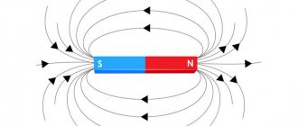
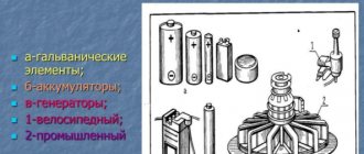
Permanent magnets
Permanent magnets can serve as a source of magnetic field (MF). They are made from magnetite. In nature it is known as iron oxide. This is a black mineral with the molecular structure of FeO·Fe2O3. The properties of magnets have been known since ancient times. Magnets have two poles - north and south.
Permanent magnets can be classified according to the following criteria:
- the material from which the magnet is made;
- form;
- scope of use.
Permanent pole magnets are made from various materials:
- ferrites - pressed products from iron oxide powders and oxides of other metals;
- rare earth - nodimium (NdFeB), samarium (SmCo), cast (metal alloys), polymer (magnetic plastics).
The shape of magnets is very different:
- cylindrical (rectangular);
- horseshoe-shaped;
- ring-shaped;
- disc-shaped.
Important! Depending on the shape, the location of the poles changes, and accordingly, the direction of the magnetic lines near the field changes.
Direction of MF lines depending on the shape of the magnet
Permanent magnets have found wide application in various sectors of the national economy:
- MRI is a medical device for diagnosing the human body;
- hard disk drives in modern computers;
- in radio engineering, in the manufacture of speakers;
- production of decorative jewelry using polymer-based magnets.
In DC motors, such magnets are mounted in the inductor housing.
Electromagnets
The next type of device designed to create an MF is an electromagnet. When electric current flows through its winding, the core becomes a magnet. Consequently, the electromagnet consists of the following parts:
- core (magnetic circuit);
- winding.
This is a kind of inductor called a solenoid.
The core can be made of ferrimagnetic material or a sheet of electrical steel.
The winding is wound with aluminum or copper wire covered with insulation.
Electromagnets (EM) can be classified according to the following parameters:
- DC magnets – neutral;
- DC magnets – polarized;
- AC devices.
Neutral EM - the creation of a magnetic flux occurs in such a way that the magnitude of attraction increases with increasing current strength and does not obey the direction of movement of the electrons.
Polarized EMs contain:
- working winding - to create a working Φ;
- permanent magnet – for inducing polarizing Φ.
The EM AC windings are powered by a sinusoidal current, so their Φ changes according to a periodic law.
Appearance of the simplest EM
Electromagnetic induction
Michael Faraday discovered a phenomenon known as electromagnetic induction. In 1831, it was noticed that if the magnetic flux Φ, which penetrates a circuit made of a closed conductor, is changed, an electric current is induced in it.
Attention! The magnitude of the electromotive force (EMF) arising in this case does not depend on the reason for the change in Φ, but is proportionally related to the change in its speed through the surface within the contour.
Electromagnetic induction
Basic formulas
Right hand or gimlet rule:
The direction of the magnetic field lines and the direction of the current creating it are interconnected by the well-known rule of the right hand or gimlet, which was introduced by D. Maxwell and is illustrated by the following drawings:
Few people know that a gimlet is a tool for drilling holes in wood. Therefore, it is more understandable to call this rule the rule of a screw, screw or corkscrew. However, grabbing the wire as in the picture is sometimes life-threatening!
Magnetic induction B:
Magnetic induction is the main fundamental characteristic of a magnetic field, similar to the electric field strength vector E. The magnetic induction vector is always directed tangentially to the magnetic line and shows its direction and strength. The unit of magnetic induction in B = 1 T is taken to be the magnetic induction of a uniform field, in which a section of conductor length l = 1 m, with a current strength in it of I = 1 A, is acted on by the maximum field - F = 1 H. Direction of force Ampere is determined by. In the CGS system, magnetic field induction is measured in gauss (G), in the SI system - in tesla (T).
Magnetic field strength H:
Another characteristic of a magnetic field is intensity , which is an analogue of D in electrostatics. Determined by the formula:
Magnetic field strength is a vector quantity, is a quantitative characteristic of the magnetic field and does not depend on the magnetic properties of the medium. In the CGS system, magnetic field strength is measured in oersteds (Oe), in the SI system - in amperes per meter (A/m).
Magnetic flux F:
Magnetic flux Ф is a scalar physical quantity that characterizes the number of magnetic induction lines penetrating a closed circuit. Let's consider a special case. In a uniform magnetic field, the magnitude of the induction vector is equal to ∣B∣, a flat closed loop of area S is placed. The normal n to the plane of the loop makes an angle α with the direction of the magnetic induction vector B. The magnetic flux through the surface is the quantity Ф, determined by the relation:
In general, magnetic flux is defined as the integral of the magnetic induction vector B through a finite surface S.
It is worth noting that the magnetic flux through any closed surface is zero (Gauss's theorem for magnetic fields). This means that the magnetic field lines do not break off anywhere, i.e. the magnetic field has a vortex nature, and also that it is impossible for the existence of magnetic charges that would create a magnetic field in the same way that electric charges create an electric field. In the SI, the unit of magnetic flux is Weber (Wb), in the CGS system it is Maxwell (Mx); 1 Wb = 108 μs.
Definition of inductance:
Inductance is the coefficient of proportionality between the electric current flowing in any closed circuit and the magnetic flux created by this current through the surface of which this circuit is the edge.
Otherwise, inductance is a proportionality coefficient in .
In SI units, inductance is measured in henry (H). A circuit has an inductance of one henry if, when the current changes by one ampere per second, a self-inductive emf of one volt appears at the circuit terminals.
The term “inductance” was proposed by a self-taught English scientist in 1886. Simply put, inductance is the property of a current-carrying conductor to accumulate energy in a magnetic field, equivalent to capacitance for an electric field. It does not depend on the magnitude of the current, but only on the shape and size of the conductor carrying the current. To increase the inductance, the conductor is wound into coils , the calculation of which is the subject of the Coil32
Right hand rule
The “right hand rule” helps determine in which direction the induced current will move. The decoding of this method, invented for memorization, is as follows:
- the right hand is placed in the MP so that the palm is located at an angle of 90° to the magnetic lines of force;
- the thumb is directed in the direction of movement of the conductor.
The induced current moves where the four fingers of the hand point.
Right hand rule
Magnetic flux: formula
Determining the value of Φ is possible using mathematical calculation. The magnetic flux formula is:
Φ = B*S*cos α,
Where:
- B – magnetic induction vector (VMI);
- S – contour area;
- cos α is the angle between the VMI and the perpendicular (normal) to the intersecting surface.
Here, B is the magnitude of the magnetic induction vector.
Explanation of the formula for determining the value of Φ
Ampere power
's imagine that there is a magnetic field with induction B. l in it , through which a current of force I , then the field will act on the conductor with a force:
This is the Ampere force . Angle alpha is the angle between the direction of the magnetic induction vector and the direction of the current in the conductor.
The direction of the Ampere force is determined by the left hand rule: if you position your left hand so that the lines of magnetic induction enter the palm, and the outstretched fingers indicate the direction of the current, the extended thumb will indicate the direction of the Ampere force.
Formula for the rate of change of magnetic flux
Based on the rate of change of magnetic fluxes through the circuit, the magnitude of the EMF induced in the circuit is determined. The speed Ei itself will be determined by the formula:
Ei = — ∆ Φ/∆t,
Where:
- ∆ Φ = Φ2 – Φ1 – change in flow (Wb);
- ∆t – change in time (s).
The unit of measurement for speed is Wb/s.
Faraday's discovery of the law of electromagnetic induction made it possible to use the work of magnetic flux to create electrical machines: generators and motors, both direct and alternating current. In them, depending on the design, either the permanent magnet changes its position relative to the frame, or the frame rotates in the MP. One way or another, an emf arises, its value depends on Φ.
Self-induction
Self-induction is the phenomenon of the occurrence of induced emf in a conductor as a result of a change in current in it.
When the current in the coil changes, the magnetic flux created by this current changes. A change in the magnetic flux passing through the coil should cause the appearance of an induced emf in the coil.
In accordance with Lenz's rule, the self-inductive emf prevents the current from increasing when the circuit is turned on and the current from decreasing when the circuit is turned off.
This leads to the fact that when a circuit is closed in which there is a current source with a constant EMF, the current strength is established after some time.
When the source is turned off, the current also does not stop instantly. The self-inductive emf that arises in this case may exceed the source emf.
The phenomenon of self-induction can be observed by assembling an electrical circuit from a coil with high inductance, a resistor, two identical incandescent lamps and a current source. The resistor must have the same electrical resistance as the coil wire.
Experience shows that when the circuit is closed, an electric lamp connected in series with a coil lights up somewhat later than a lamp connected in series with a resistor. The increase in current in the coil circuit during closure is prevented by the self-induction emf, which occurs when the magnetic flux in the coil increases.
When the power source is turned off, both lamps flash. In this case, the current in the circuit is maintained by the self-induction emf that occurs when the magnetic flux in the coil decreases.
Self-inductive emf \( \varepsilon_{is} \), arising in a coil with inductance \( L \), according to the law of electromagnetic induction is equal to:
The self-inductive emf is directly proportional to the inductance of the coil and the rate of change of current in the coil.
Video
Coffee capsule Nescafe Dolce Gusto Cappuccino, 3 packs of 16 capsules
1305 ₽ More details
Coffee capsules Nescafe Dolce Gusto Cappuccino, 8 servings (16 capsules)
435 ₽ More details
QLED TVs