A standard electric pole SV 9.5-2.0 has the following dimensions: length 9500 (mm), width 220 (mm), thickness 165 (mm).
Dimensions of electric poles:
— length (L): from 9500 (mm) to 13500 (mm); — height (H): 650 (mm), 700 (mm); — width (B): 220 (mm).
Catenary support racks:
— length (L): 13600 (mm); — height (H): from 200 (mm) to 600 (mm); — width (B): 290 (mm).
Contact line support racks for transport:
— length (L): 10500 (mm), 13500 (mm); — height (H): 412 (mm); — width (B): 220 (mm).
How much does a power line pole cost?
Price list for power line supports
| Name | Price, per piece * |
| Stand ( support ) for power lines SV 110-5 | 8625 rub. |
| Stand ( support ) for power lines SV 95-20 | 5000 rub. |
| Stand ( support ) for power lines SV 95-2s | 5700 rub. |
| Stand ( support ) for power lines SV 105-3.5 | 7800 rub. |
Requirements for power lines up to 0.4 kV in populated areas
Voltage 0.4 kV is the maximum for input into a private house. For such lines within cities and SNT, requirements have been developed for the distance from supports to utility facilities.
Diagram indicating the distances from supports to residential buildings
The distance between the line posts is no more than 50 meters. It depends on the wind and snow load in the installation region. All calculations are made by specialists. The distances they recommend should not be exceeded.
The maximum distance from the main support to the wall of the house is 25 meters. Otherwise, you will need to install additional supports.
The distance from the main to the additional distribution pole is not clearly standardized. Its location must be determined by analyzing the site plan, points of entry of electrical lines into the house and installation locations of the main supports.
The sag of the tensioned wire in the roadway area should be no more than 6 meters above the ground, and in the pedestrian path area - 3.5 m.
The distance from the additional distribution support to the wall of the house should be no more than 10 m and no less than 2 m. From the fence to the support should be at least 1 m, which is enough to provide space for electricians if it is necessary to carry out work on the pole.
The support is not prohibited from being located on the inside of the site. However, it is necessary to ensure unimpeded access to it for energy services.
The minimum standard height for cable entry from the power line into the house is 2.75 m.
Who should change electric poles?
If these are private poles
, then replacement, if necessary,
must
be carried out by the gardener-owner himself.
However, in most societies poles
, like all electrical equipment, are part of public property, explains Pyotr Kozlov, chairman of the Volgograd Regional Union of Gardeners and Gardeners.
Interesting materials:
Which of the following languages belongs to the Slavic language group of the Indo-European language family? What are the pronouns in English? Which peoples speak the languages of the Altai family? What are the main programming languages? What are the main types of variables used in the Visual Basic programming language? What are the most ancient languages? What data types exist in VBA? What place does the Russian language occupy in the world in terms of the number of speakers? What kind of coating should there be on the tongue? Which European language is easier to learn?
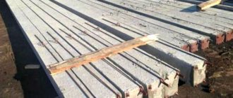
Features and advantages of reinforced concrete power transmission line structures
Reinforced concrete pillars are considered the most common and reliable option. They are characterized by:
- high strength parameters;
- durability (50 or more years of reliable operation);
- corrosion resistance;
- fire safety;
- resistance to aggressive environments, moisture, low temperatures.
Manufacturers produce poles of various sections and sizes, which vary depending on the purpose of the supporting product and the loads placed on it (ice and wind). According to the design solution, products are divided into single-post or portal versions, free-standing or guyed. Single-post products are aimed at installing street lighting. Concrete electric poles having an anchor-corner design with guy wires are used for high-voltage networks.
If we look at the product labeling, the letter designations suggest that:
- products with the abbreviation SV are vibration racks made from prestressed or non-stressed building material;
- SK – conical, annular section;
- SC are cylindrical, which are produced from heavy types of concrete by centrifugation.
The value of the first digit reflects the length of the product, indicated in decimeters. The second numerical designation of the marking indicates the load-bearing capacity of the beam (during bending testing).
The strength characteristics of concrete poles for electrical networks are ensured by the use in their production of concrete mixtures of classes B30, B 40 and B45, granite crushed stone as a filler and high-strength steel reinforcement.
Height of power poles
Tel, 389-06-74, 389-06-75
The enterprise LLC "AZMK" is engaged in the production of metal power transmission line supports. In terms of the level of equipment and available production capacity, we are a solid participant in the market for the production of metal power transmission line supports. The capacity of the enterprise for the production of metal structures is 1500 - 2000 tons per month.
We are looking for responsible people who want to earn money
Today, AZMK LLC is equipped with high-performance equipment from such manufacturers as FIN CNC MACHINE, GEKA, Bomar, AJAN and Russian, used in such technological operations as cutting, chopping, bending, milling, drilling, piercing, welding and marking of corner and sheet metal rolled metal Currently, the LLC AZMK enterprise has the ability to develop KMD drawings, in its own design bureau, produce and ship metal structures of any complexity from Art. 3 and Art. 09G2S using its own vehicles or railway transport, namely:
- Metal supports for power lines 35-500 kV, complete with hardware for their assembly, including supports for HVL 220.
- Cross piles, screw piles with equipment, foundation beams, grillages.
- Floodlight masts - permanent residence, PMS of various designs, up to 40 meters high and free-standing lightning rods.
- Antenna supports for radio relay communications complete with hardware for assembly and anchor bolts.
- Building metal structures for industrial and civil purposes: columns, trusses, braces, beams, crossbars, crane beams, monorails, fences, platforms, stairs, etc.
What standards exist for installing a concrete pillar on your site?
First, you should take into account that the depth of burying the support in the ground should be below the freezing level, that is, about 1.5–2 meters. You won't be able to install a concrete pillar yourself. Because:
- The height reaches at least 5 meters; it is impossible to install it in a strictly vertical position without the help of a machine.
- The need for insulators and a special reliable metal mount on a pole, which must reliably withstand all gusts of wind and ice in winter.
- The need to de-energize the line, which finally shatters all the hopes of desperate self-taught electricians.
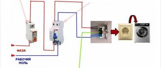
Installation of wiring in the house
After preparing and installing the pole on the site, it is necessary to address the issue of connecting electricity to a private house. This can be done both from the supply support, if it is located on the site, and through an intermediate pole. The following methods are used to connect them:
- bare aluminum wire;
- copper or aluminum cable;
- SIP (self-supporting insulated wire).
Cables can be laid from an intermediate or supply pole to the house not only by air, but also underground. This method is used much less frequently than steel cables stretched through the air.
The condition of power lines is significantly influenced by the type of supports used. For 100 years, the wooden support remained one of the main structures of overhead lines (OL).
Only in the 60s of the last century they began to make it with protective impregnation. At that time, instructions were given on the use of antiseptics, but they were poorly implemented, which led to rotting of the supports. The widespread transition to reinforced concrete pillars did not solve all the problems, since they showed disadvantages that are not inherent in wood products:
- fragility upon impact;
- low bending strength;
- significant weight;
- presence of leakage currents.
Maintenance and repair of wooden poles
Wooden power line supports are subject to periodic inspections and repairs. In the summer, at a depth of 30-50 cm, the depth of wood decay is checked. If the diameter of the log is 25 cm and there is more than 3 cm of rot, it is considered unsuitable and must be replaced.
Major repairs of lines, where mostly wooden supports are installed, are done at least every 6 years. The remaining repair work is carried out within a time frame depending on available resources.
The fire hazard of wooden supports requires labor-intensive operations to reduce it. If there are wooden attachments around, a ditch 0.4 m deep is dug and grass and bushes are removed.
Parts from the supports are replaced with new ones while the line is running. Here it is necessary to take into account that on parts of the structure the loads may exceed the design ones.
If the poles have deviated from the vertical by an unacceptable amount, additional loads may cause the wires to change position and get caught or touch parts. Displacements occur due to weakening of the foundation or sealing of the base of the support, displacement of the soil, weakening of connections.
Alignment is carried out using steel cables attached to a stand. The base is dug to a depth of 1.5 m and the support is straightened using a traction mechanism. Then the pit is filled and compacted.
When the stand warps due to a loose connection with the bandage, it is straightened without displacing the stepsons.
A bandage is installed on the rotted rack. Before this, the rot is removed and the pillar is covered with antiseptic paste.
Damaged parts are reinforced with temporary overlays made of wood or metal, using half-clamps, bolts and banding wire.
Before being transported to the track, parts are checked for compliance with design parameters.
To increase the service life of the racks, they should be additionally impregnated during operation by diffusion. Antiseptic bandages are installed on the underground and above-ground parts of the support and on the joints. Antiseptic paste is applied into cracks and on the tops of racks with attachments.
Due to the fact that the mass of the wooden support is small, heavy equipment is rarely required for repairs.
The support that cannot be repaired is freed from all loads and replaced with a new one using special equipment.
Advantages
Wooden support will never be written off due to the following advantages:
- Low cost.
- Light weight.
- When a wooden pole falls, the weight of which is 3 times less than a reinforced concrete one, it hangs on the wires without the “domino” effect characteristic of heavy poles.
- Indispensable in areas with increased seismic activity.
- Better withstand wind loads.
- High dielectric characteristics.
- Long service life if properly manufactured (up to 40 years).
- Do not require special maintenance.
Classification of supports [edit | edit code ]
By purpose [edit | edit code ]
- Intermediate supports
are installed on straight sections of the overhead line route; they are intended only to support wires and cables and are not designed for loads from the tension of wires along the line. Typically they make up 80-90% of all overhead line supports. - Corner supports
are installed at the angles of rotation of the overhead line route; under normal conditions, they perceive the resultant tension forces of wires and cables of adjacent spans, directed along the bisector of the angle that complements the angle of rotation of the line by 180°. At small rotation angles (up to 15-30°), where the loads are small, angular intermediate supports are used. If the rotation angles are greater, then corner anchor supports are used, which have a more rigid structure and anchor fastening of the wires. - Anchor supports
are installed on straight sections of the route for crossing engineering structures or natural barriers; they absorb longitudinal loads from the tension of wires and cables. Their design is rigid and durable. - End supports
are a type of anchor and are installed at the end or beginning of a line. Under normal operating conditions of overhead lines, they perceive the load from one-sided tension of wires and cables. - Special supports
: transposition - to change the order of wires on the supports; branch lines - for installing branches from the main line; cross - when overhead lines intersect in two directions; anti-wind - to enhance the mechanical strength of overhead lines; transitional - when crossing overhead lines through engineering structures or natural barriers. - Stylized power line supports
are sculpture supports that, in addition to the main function of holding wires, perform an aesthetic one.
According to the method of fixation in the ground [edit | edit code ]
- Supports installed directly into the ground
- Supports installed on foundations
- classic (with a wide base of more than 4 m2), usually frame (frame) filled with concrete or a weight filled with sand and gravel mixture
- narrow-base (less than 4 m2) (for example: mounted on a steel pipe, steel screw or reinforced concrete pile)
By design [edit | edit code ]
- Free-standing supports
- single-post
- multi-post
- Supports with guys
- Emergency reserve cable-stayed supports
- Single-chain
- Double circuit
- Multi-chain
By the number of chains [edit | edit code ]
By voltage [edit | edit code ]
The supports are divided into supports for lines 0.4, 6, 10, 35, 110, 220, 330, 500, 750, 1150 kV. These groups of supports differ in size and weight. The greater the tension, the higher the support, the longer its traverses and the greater its weight. The increase in the size of the support is caused by the need to obtain the required distances from the wire to the body of the support and to the ground, corresponding to the PUE for different line voltages.
According to the material of manufacture [edit | edit code ]
- Reinforced concrete - made of concrete reinforced with metal. For lines 35-110 kV and above, supports made of centrifuged concrete are usually used. The advantage of reinforced concrete supports is their resistance to corrosion and the effects of chemicals in the air. The main disadvantage is significant weight, a relatively high percentage of defects during transportation (chips, cracks) and concrete spalling in the surface layer of soil due to exposure to moisture and cyclic temperature changes (freezing-thawing).
- Metal - made from special grades of steel. Individual elements are connected by welding or bolts. As a rule, to prevent oxidation and corrosion, the surface of metal supports is galvanized (including by thermal spraying) or periodically painted with special paints.
- Metal lattice supports
- Metal polyhedral supports
- closed profile (six-, eight-, etc. edges)
- open profile (triangular and square section)