Unified State Exam 2022 in Physics ›
A magnetic field is a special form of matter that exists around moving electric charges - currents.
The sources of the magnetic field are permanent magnets and current-carrying conductors. A magnetic field can be detected by the effect on a magnetic needle, a current-carrying conductor, and moving charged particles.
To study the magnetic field, a closed flat circuit with current is used (frame with current).
The rotation of a magnetic needle near a conductor through which current flows was first discovered by Oersted in 1820. Ampere observed the interaction of conductors through which current flowed: if the currents in the conductors flow in one direction, then the conductors attract, if the currents in the conductors flow in opposite directions, then they repel.
Properties of magnetic field:
- magnetic field is material;
- source and field indicator – electric current;
- the magnetic field is vortex - its lines of force (magnetic induction lines) are closed;
- the magnitude of the field decreases with distance from the field source.
Important! The magnetic field is not potential. Its work on a closed trajectory may not be equal to zero.
Magnetic interaction is the attraction or repulsion of electrically neutral conductors when an electric current is passed through them.
The magnetic interaction of moving electric charges is explained as follows: every moving electric charge creates a magnetic field in space that acts on moving charged particles.
The strength characteristic of the magnetic field is the magnetic induction vector \( \vec{B} \). The magnitude of the magnetic induction vector is equal to the ratio of the maximum value of the force acting from the magnetic field on a current-carrying conductor to the current strength in the conductor \( I \) and its length \( l \):
The designation is \( \vec{B} \), the SI unit is tesla (T).
1 T is the induction of a magnetic field in which a maximum force of 1 N acts on each meter of conductor length at a current of 1 A.
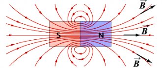
The direction of the magnetic induction vector coincides with the direction from the south pole to the north pole of the magnetic needle (the direction indicated by the north pole of the magnetic needle), freely established in a magnetic field.
The direction of the magnetic induction vector can be determined by the gimlet rule :
if the direction of translational movement of the gimlet coincides with the direction of the current in the conductor, then the direction of rotation of the gimlet handle coincides with the direction of the magnetic induction vector.
To determine the magnetic induction of several fields, the principle of superposition :
the magnetic induction of the resulting field created by several sources is equal to the vector sum of the magnetic induction of the fields created by each source separately:
A field at each point of which the magnetic induction vector is the same in magnitude and direction is called homogeneous.
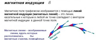
The magnetic field is visually depicted in the form of magnetic lines or magnetic induction lines. A magnetic induction line is an imaginary line, at any point of which the magnetic induction vector is directed tangentially to it.
Properties of magnetic lines:
- magnetic lines are continuous;
- magnetic lines are closed (i.e. in nature there are no magnetic charges similar to electric charges);
- magnetic lines have a direction related to the direction of the current.
The density of the arrangement allows us to judge the size of the field: the denser the lines are, the stronger the field.
A flat closed circuit with current placed in a uniform magnetic field is acted upon by a moment of force \( M \):
where \( I \) is the current strength in the conductor, \( S \) is the surface area covered by the circuit, \( B \) is the magnitude of the magnetic induction vector, \( \alpha \) – the angle between the perpendicular to the contour plane and the magnetic induction vector.
Then for the module of the magnetic induction vector we can write the formula:
where the maximum moment of force corresponds to the angle \( \alpha \) = 90°.
In this case, the lines of magnetic induction lie in the plane of the frame, and its equilibrium position is unstable. The position of the frame with current will be stable in the case when the plane of the frame is perpendicular to the lines of magnetic induction.
Magnet interaction
Permanent magnets are bodies that retain magnetization for a long time, that is, creating a magnetic field.
The main property of magnets is to attract bodies made of iron or its alloys (for example steel). Magnets can be natural (made from magnetic iron ore) or artificial, which are magnetized iron strips. The areas of a magnet where its magnetic properties are most pronounced are called poles. A magnet has two poles: north \( N \) and south \( S \).
Important! Outside the magnet, magnetic lines leave the north pole and enter the south pole.
It is impossible to separate the poles of a magnet.
Explained the existence of a magnetic field in permanent magnets Ampere. According to his hypothesis, elementary electric currents circulate inside the molecules that make up a magnet. If these currents are oriented in a certain way, then their actions add up and the body exhibits magnetic properties. If these currents are randomly located, then their action is mutually compensated and the body does not exhibit magnetic properties.
Magnets interact: like magnetic poles repel, unlike ones attract.
Dynamo effect
At the moment we have a rotating liquid conducting mass. However, this is not enough to create and maintain a magnetic field. It would require, for example, an external magnetic field surrounding the Earth: the latter would induce a current in the metal core, which would produce the Earth's magnetic field.
The problem is that the Earth is not bathed in an external magnetic field. Not a powerful enough field anyway.
Thus, if there were a point magnetic pulse, an electric current would appear in the Earth's core, but it would dissipate very quickly, and the Earth's magnetic field would also disappear quickly.
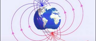
Obviously, the Earth has a very real magnetic field. The modern explanation for the Earth's magnetic field is the dynamo effect.
It does not yet explain the origin of the magnetic field, but it does explain how this field—the real one—can be maintained without disappearing.
So let's take planet Earth as described above: with a liquid, spinning metal core.
Let us assume that the Earth was in the past in a pre-existing external magnetic field. As stated above, this field will cause a current in the liquid parts of the core, and this current will create the Earth's magnetic field, opposite to the external field.
Now we must take into account convection phenomena associated with the internal heat of the Earth, and the phenomena of rotation of liquid masses associated with the rotation of the Earth. These are two primary energy sources that will gradually be converted into electromagnetic energy and emit a magnetic field.
These metal "cyclones" melted in the outer core will take the form of rotating cylinders that will be aligned with the Earth's rotation axis (thus the North-South axis). By doing this, the lines of electric current induced by the magnetic field will seem to wrap around themselves, forming a coil, and stretch in length by convection. Electric current lines lengthen: this is if the inductive coil becomes larger and the magnetic field becomes stronger.
Thus, an effect occurs where the coil is stretched and allows an increase in the amount of magnetic energy from thermal convection and due to the rotation of the Earth.
As a result, the Earth's magnetic field, as opposed to dissipating, manages to maintain itself: the rotation and convection of the Earth at the core constantly pumps energy into the electromagnetic system to compensate for losses.
Now that magnetic energy is produced, the original magnetic field in which the Earth is said to have bathed may disappear: it is no longer necessary.
The generated magnetic field is supported by layers of molten liquid metal that rise to the surface.
When these layers reach the outer limit of the core, there is no more convection (in that layer) and the field disappears. However, this field will have induced electric currents in the lower layers, which will also produce their own magnetic field, and perpetuate the production of the magnetic field.
Thus, as long as there is convection in the core and the rotation of our planet, producing Coriolis forces, the magnetic field will exist.
Convection movements are complex, have chaotic components and can sometimes change direction. It is therefore possible that the Earth's magnetic field will change and the magnetic poles will move and may even reverse. In the history of our planet, these reversals have occurred 300 times in the last 200 million years, approximately every 660,000 years; the last one occurred about 780,000 years ago.
Magnetic field of a current-carrying conductor
An electric current flowing through a current-carrying conductor creates a magnetic field in the space surrounding it. The greater the current passing through the conductor, the stronger the magnetic field that arises around it.
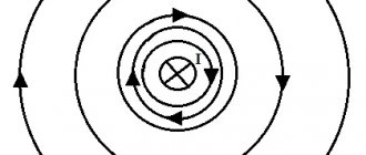
The magnetic lines of force of this field are located in concentric circles, in the center of which there is a current-carrying conductor.
The direction of the magnetic field lines around a current-carrying conductor is always in strict accordance with the direction of the current passing through the conductor.
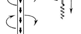
The direction of magnetic field lines can be determined by the gimlet rule : if the translational movement of the gimlet (1) coincides with the direction of the current (2) in the conductor, then the rotation of its handle will indicate the direction of the magnetic field lines (4) around the conductor.
When the direction of the current changes, the magnetic field lines also change their direction.
As you move away from the conductor, the magnetic field lines are less frequent. Consequently, the magnetic field induction decreases.
The direction of current in a conductor is usually represented by a dot if the current is going towards us, and a cross if the current is directed away from us.
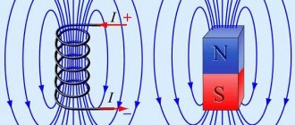
To obtain strong magnetic fields at low currents, they usually increase the number of current-carrying conductors and make them in the form of a series of turns; such a device is called a coil.
In a conductor bent in the form of a coil, the magnetic fields generated by all sections of this conductor will have the same direction inside the coil. Therefore, the intensity of the magnetic field inside the coil will be greater than around a straight conductor. When the turns are combined into a coil, the magnetic fields created by the individual turns add up. In this case, the concentration of field lines inside the coil increases, i.e., the magnetic field inside it intensifies.
The greater the current passing through the coil, and the more turns there are in it, the stronger the magnetic field created by the coil. The magnetic field outside the coil also consists of the magnetic fields of individual turns, but the magnetic field lines are not so densely located, as a result of which the intensity of the magnetic field there is not as great as inside the coil.
The magnetic field of a current-carrying coil has the same shape as the field of a straight permanent magnet: magnetic lines of force exit from one end of the coil and enter the other end. Therefore, a current-carrying coil is an artificial electric magnet. Typically, a steel core is inserted inside the coil to enhance the magnetic field; such a coil is called an electromagnet.
The direction of the magnetic induction lines of a current-carrying coil is found using the right-hand rule :
if you mentally clasp the current coil with the palm of your right hand so that four fingers indicate the direction of the current in its turns, then the thumb will indicate the direction of the magnetic induction vector.
To determine the direction of the magnetic field lines created by a turn or coil, you can also use the gimlet rule :
if you rotate the handle of the gimlet in the direction of the current in the coil or coil, then the translational movement of the gimlet will indicate the direction of the magnetic induction vector.
Electromagnets have found extremely wide application in technology. The polarity of an electromagnet (the direction of the magnetic field) can also be determined using the right-hand rule.
Magnetic induction
Magnetic induction (MI) is the force definition of MF. This is a vector quantity.
One of the main characteristics of a magnetic field is the vector potential.
The formula for magnetic field induction is measured through the magnetic induction vector (B).
B=Fmax/I*l,
where Fmax is the greatest force exerted by the MF on the conductor; I is the current strength in the conductor; l - length.
The MI vector has units of measurement - tesla (T).
The direction of the MI vector is the direction from the south pole to the north pole of the magnetic needle installed in the MP.
The MI line is a non-existent straight line , where at any place the MI vector is directed tangentially to it.
Properties of a magnetic line:
- permanence;
- isolation;
- orientation.
The more magnetic lines, the stronger the MF.
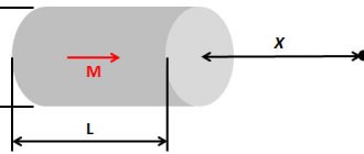
If we consider a magnetic field in free space (without its surrounding environment), then the concept used is not the magnetic vector, but the intensity vector (H), equal to the difference between the magnetic vector and the magnetization vector (M).
H = B - M
If there is more than one field, then the MI vector is determined by the principle of superposition: the MI of the main field, which consists of many sources, can be found through the sum of the MI of all fields included in the MP.
Ampere power
Ampere force is the force that acts on a current-carrying conductor in a magnetic field.
Ampere's law: a conductor with a current of force \( I \) of length \( l \), placed in a magnetic field with induction \( \vec{B} \), is acted upon by a force whose modulus is equal to:
where \( \alpha \) is the angle between the current-carrying conductor and the magnetic induction vector \( \vec{B} \).
The direction of the Ampere force is determined by the left hand rule : if the palm of the left hand is positioned so that the component of the magnetic induction vector \(B_\perp \) perpendicular to the conductor enters the palm, and four extended fingers indicate the direction of the current in the conductor, then the bent one The 90° thumb will show the direction of the Ampere force.
Ampere's force is not central. It is directed perpendicular to the lines of magnetic induction.
Ampere power is widely used. In technical devices, a magnetic field is created using conductors through which electric current flows. Electromagnets are used in an electromechanical relay for remotely turning off electrical circuits, a magnetic crane, a computer hard drive, a VCR recording head, a TV picture tube, and a computer monitor. Electric motors are widely used in everyday life, in transport and in industry. The interaction of an electromagnet with the field of a permanent magnet made it possible to create electrical measuring instruments (ammeter, voltmeter).
The simplest model of an electric motor is a current-carrying frame placed in the magnetic field of a permanent magnet. In real electric motors, instead of permanent magnets, electromagnets are used, and instead of a frame, windings with a large number of turns of wire are used.
Electric motor efficiency:
where \( N \) is the mechanical power developed by the engine.
The efficiency of the electric motor is very high.
Algorithm for solving problems about the action of a magnetic field on current-carrying conductors:
- make a schematic drawing on which to indicate a conductor or circuit with current and the direction of the field lines;
- mark the angles between the field direction and individual contour elements;
- using the left-hand rule, determine the direction of the Ampere force acting on a current-carrying conductor or on each element of the circuit, and show these forces in the drawing;
- indicate all other forces acting on the conductor or circuit;
- write down formulas for the remaining forces mentioned in the problem. Express forces in terms of the quantities on which they depend. If the conductor is in equilibrium, then it is necessary to write down the condition of its equilibrium (the sum of forces and moments of forces being equal to zero);
- write down Newton's second law in vector form and in projections;
- solve the resulting system of equations for an unknown quantity;
- check the solution.
Basic characteristics of the magnetic field
A magnetic field (hereinafter referred to as MF) is a matter that is located and moves around currents (electric charges).
MP arises from:
- Current of charged particles.
- An electric field that changes over time.
- Magnetic moments.
To study MF, a current frame is used.
A frame with current is a continuous, even contour with current.
MP properties:
- MP has a material basis;
- electric current is an indicator for MP, and without it MP cannot exist;
- The magnetic field is circular, that is, its lines of force (magnetic induction lines) are continuous;
- The further away the field source is, the weaker and smaller the MF becomes.
MF can be graphically represented in the form of lines or induction lines.
Lorentz force
The Lorentz force is a force acting on a moving charged particle from a magnetic field.
Formula for finding the Lorentz force:
where \( q \) is the particle charge, \( v \) is the particle velocity, \( B \) is the magnitude of the magnetic induction vector, \( \alpha \) is the angle between the particle velocity vector and the vector of magnetic induction.
The direction of the Lorentz force is determined by the left hand rule : if the palm of the left hand is positioned so that the component of the magnetic induction vector \( B_\perp \) perpendicular to the conductor enters the palm, and four extended fingers indicate the direction of the velocity of the positively charged particle, then the bent at 90° the thumb will show the direction of the Lorentz force.
If the charge of the particle is negative, then the direction of the force is reversed.
Important! If the velocity vector is co-directed with the magnetic induction vector, then the particle moves uniformly and rectilinearly.
In a uniform magnetic field, the Lorentz force bends the trajectory of a particle.
If the velocity vector is perpendicular to the magnetic induction vector, then the particle moves in a circle whose radius is equal to:
where \( m \) is the mass of the particle, \( v \) is the velocity of the particle, \( B \) is the magnitude of the magnetic induction vector, \( q \) is the charge of the particle.
In this case, the Lorentz force plays the role of a centripetal force and its work is zero. The period (frequency) of revolution of a particle does not depend on the radius of the circle and the speed of the particle. Formula for calculating the period of revolution of a particle:
Angular velocity of a charged particle:
Important! The Lorentz force does not change the kinetic energy of the particle and its velocity modulus. Under the influence of the Lorentz force, the direction of the particle's velocity changes.
If the velocity vector is directed at an angle \( \alpha \) (0° < \( \alpha \) < 90°) to the magnetic induction vector, then the particle moves along a helical line.
In this case, the particle velocity vector can be represented as the sum of two velocity vectors, one of which, \( \vec{v}_2 \), is parallel to the vector \( \vec{B} \), and the other, \( \vec {v}_1\), – is perpendicular to it. The vector \( \vec{v}_1 \) does not change either in magnitude or direction. The vector \( \vec{v}_2 \) changes in direction. The Lorentz force will impart an acceleration to the moving particle perpendicular to the velocity vector \( \vec{v}_1 \). The particle will move in a circle. The period of revolution of a particle in a circle is \( T \).
Thus, uniform motion along the induction line will be superimposed on circular motion in a plane perpendicular to the vector \( \vec{B} \). The particle moves along a helical line with a step \( h=v_2T \).
Important! If a particle moves in electric and magnetic fields, then the total Lorentz force is equal to:
The peculiarities of the movement of a charged particle in a magnetic field are used in mass spectrometers - devices for measuring the masses of charged particles; particle accelerators; for thermal insulation of plasma in Tokamak installations.
Algorithm for solving problems about the action of a magnetic (and electric) field on charged particles:
- make a drawing, indicate the magnetic (and electric) field lines on it, draw the vector of the initial velocity of the particle and note the sign of its charge;
- depict the forces acting on a charged particle;
- determine the type of particle trajectory;
- expand the forces acting on a charged particle along the direction of the magnetic field and in the direction perpendicular to it;
- draw up the basic equation for the dynamics of a material point for each of the directions of force distribution;
- express forces through the quantities on which they depend;
- solve the resulting system of equations for an unknown quantity;
- check the solution.
Electric field
Electric field (EF) is matter created by charged particles interacting with each other.
Quantitatively, EP can be characterized by the concept of electric field strength. Since force has a direction, tension also has a direction, so it is a vector quantity. This tension can be determined by the formula:
E=F/q, where E is the EF voltage,
F is the force that affects the charge,
q is the amount of charge.
Just like MI, the strength of several electric fields can be calculated using the principle of superposition.
Types of electronic signature:
- Static (has stationary charges).
- Magnetic (charges pass through a conductor).
- Stationary (if the current-carrying conductor does not move or change).
- Electromagnetic.