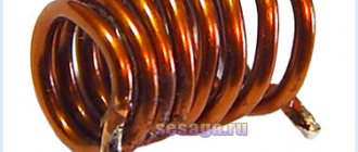
Coil
An inductor is a metal or ferrite core around which several turns of copper wire are wound. The element has the following properties:
- Due to inductance, the rate of change of currents is limited.
- As the frequency of the current increases, the coil is able to increase its resistance (skin effect).
- Creates a magnetic field.
- Increases and accumulates tension.
- Creates a phase shift in alternating current.
- Proportional to the speed of current movement, it creates a self-inductive emf.
All these properties are used in the development of radio receivers, frequency generators, testers, magnetometers and other types of complex equipment.
Design and varieties
All types of inductors have the same design, regardless of their application. The features introduced to obtain individual parameters affect the type of part.
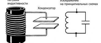
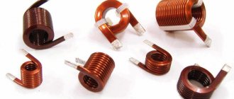
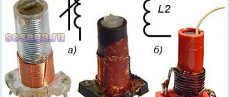
- Solenoid. Component with increased overall length of winding wire. The winding is larger than the diameter of the part.
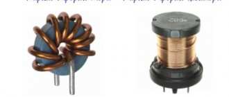
- Toroidal. In such a coil, the solenoid is made in the shape of a “torus”.
- Multilayer type, has several rows of winding.
- Sectioned. The winding has several divided sections, sometimes made of wire of different sections. The best known coil of this type is the transformer or choke.
- Universal, can combine several winding options at once.
Regardless of design, all coils operate on the same principle.
Principle of operation
An inductor only works when electric current passes through a set of turns of winding. When an element is connected to an electrical circuit, current begins to flow through the coil. Due to the interaction of the wire with the metal core, a magnetic flux is created. The flux is completely proportional to the inductance of the coil and the magnitude of the current. The magnitude of the magnetic flux can be calculated using the following formula: Ф=L×I.
The elements of the formula are:
- “F” is the magnitude of the magnetic flux.
- "L" - induction.
- “I” is the current value.
The number of turns affects the magnitude of the self-induction emf. The turns interact not only with the core, but also with each other, which leads to an increase in EMF.
In an alternating voltage circuit, the magnitude of the EMF can provoke a phase difference between voltage and current up to 90 degrees.
Operating principle
The principle of operation of an inductor is the creation and interaction of magnetic flux by the turns of the winding.
If we take a single turn in a simplified case, then when an electric current passes through it, a magnetic flux is created moving along the surface of the circuit, proportional to the magnitude of the current and the value of the inductance:
Ф=L·I, where
Ф – magnetic flux;
L – inductance;
I – current strength.
Important! In the vast majority of cases, coils are a multi-turn design, therefore they form a complex surface and parameter calculations are carried out in a simplified form.
Magnetic flux of solenoidal coil
The formation of a magnetic flux by each of the turns and its interaction with the others (magnetic induction) leads to the emergence of self-induction emf, which consists in the fact that when the magnitude of the flowing current in the coil changes, an emf is formed and, accordingly, a current directed to counteract the changes.
In the case of alternating current, this results in the current phase lagging behind the voltage phase by 90°. This property is used in reactance compensators (reactors), chokes, and delay lines.
Important! The magnitude of the self-induction EMF is directly proportional to the rate of change of current. This allows the development of high-voltage voltage sources. An automobile ignition coil consists of two windings - low voltage and high voltage. When the power is disconnected in the low-voltage winding, a self-induction EMF pulse is formed in it, which reaches tens of thousands of volts in the high-voltage winding.
Automotive ignition coil
The inductor resistance has two components:
- Inductive reactance;
- Loss resistance.
You may be interested in what is phase and zero in electricity
Inductive reactance (reactance, impedance) depends on the frequency of the flowing current:
XL = 2·π·f·L, where
π – 3.14;
f – frequency;
L – inductance.
Loss resistance includes:
- Wire losses (coil resistance);
- Eddy current losses;
- Core loss;
- Dielectric losses.
Important! Some losses are also introduced by distributed capacitance, which is reduced by using a special winding configuration and dividing it into sections.
The main share of losses comes from active resistance.
Inductance
The inductance of a coil is its ability to store electricity. This setting depends on:
- Number of turns.
- Wire cross-sections and lengths.
- Design features of the part.
- From the material, length, diameter and shape of the core.
- From the distance between turns.
- Availability of a screen.
In radio electronics it is not customary to indicate the value of inductance. Manufacturers mark parts with the number of turns and indicate the type of core.
Active resistance
An inductor not connected to an electrical circuit has only active resistance.
It is created by a copper wire and depends on its length and cross-section. Active resistance can increase only after being connected to the circuit. In this case, the processes occurring inside the element depend on the type of current.
Power in a circuit with reactive radioelements
When such elements are connected to a circuit in even quarters of a period, the power will have a negative value (at this time the component directs the accumulated energy to the voltage source). As a result, the energy use of the element for the entire cycle turns out to be zero. This means that no energy is released on it, so such parts are depicted as cold on electrical circuits. In reality, the situation may be slightly different (this depends on the parameters of a particular element); it happens that small heat losses on the capacitor or solenoid still occur. But they will not be significant, measured in square meters.
D.C
A magnetic field is created in an inductor connected to direct current. Its value depends on the number of turns on the core. At the same time, self-induction emf occurs when a magnetic flux moves, which, depending on its strength and speed, pushes part of the voltage onto the surface of the winding.
Due to the formation of EMF, the effect of underestimating the increase in current in this circuit occurs. The current, having a certain strength, is not able to increase instantly, since it is affected by the resistance of the coil. Gradually overcoming the limitation, the current gradually increases and reaches normal values. The rate of this transient process is calculated using the following values:
- "L" - inductance, Henry;
- “R” is the resistance of the electrical circuit, ohms. The value of the entire circuit with the coil is taken;
- “t” — transition process time, sec.
The calculation formula is as follows: t=L/R. This formula also uses the number of turns of the element. For example, t=5×0.7/70=0.05 seconds, where 5 is the number of turns.
For inductors with a primary and secondary winding, the inductive emf proceeds in a slightly different way. This difference is created due to the difference in the sections of the turns. In such a part, the EMF does not prevent the voltage from increasing, but is directed along with the interrupted current in one direction.
In transformers, the primary winding creates the effect of greatly increasing the voltage at the output contacts. This can be achieved by changing the current on the primary winding. Taking into account the instantaneous change in current strength (simultaneous opening), an emf pulse with an amplitude of tens of kilovolts is induced in the secondary winding. An example of this phenomenon is the ignition coil of a car. Its magnetic field allows it to reach voltages of thousands of volts, despite the fact that it itself runs on a 12-volt battery.
Inductive reactance in an AC circuit
One of the main characteristics of electrical circuits is resistance, which can be active or reactive. Typical representatives of active resistance are considered to be ordinary consumers - lamps, incandescent lamps, resistors, heating coils and other elements in which electric current performs useful work.
Reactive includes inductive and capacitive reactance, located in intermediate electricity converters - inductive coils and capacitors. These parameters must be taken into account when performing various calculations. For example, to determine the total resistance of a circuit section, the active and reactive components are added. Addition is carried out geometrically, that is, in a vector way, by constructing a right triangle. In it, both legs are both resistances, and the hypotenuse is total. The length of each leg corresponds to the effective value of one or another resistance.
Alternating current
Alternating current is very different from direct current. Therefore, its effect on the inductor will also be very different. In addition to active resistance, the coil connected to an alternating current source also has inductive resistance.
The active resistance of a coil not connected to the circuit depends only on the brand of wire, its length and cross-section. When measuring the resistance of a coil disconnected from the circuit, the tester will only show the ability of the wire itself to resist the passage of current. At its core, the active resistance of this element will be equal to 0 + the connected resistor. With this ratio, the coil with its 0 resistance is ideal. For a more accurate measurement of resistance at rest, it is important that the part is completely disconnected from the circuit. When measured on the circuit, the resistance will be increased due to the parameters of other radio components.
Inductive reactance occurs only after connecting the coil to an alternating current circuit. It depends on the frequency of the current and the number of turns. Inductive reactance can be determined using a simple formula: XL=2×π×f×L. In this expression:
- "XL" - inductive reactance.
- “π” is the number “pi” equal to 3.14.
- “f” is the frequency response of the current.
- "L" - inductance.
When alternating current passes through the turns of the coil, the effect of displacement of a fraction of the currents by magnetic fluxes is created. This property is similar to the effect of direct current. The main difference lies in the lateral displacement. The magnetic field of each turn exerts pressure on the field of the next turn. Thus, the active resistance increases.
This effect increases depending on the cross-section of the wire, its conductivity and temperature. The proximity effect, which greatly influences the increase in active resistance, is reduced by selecting the cross-section of the winding wire. Reducing the proximity effect is unacceptable by increasing the distance between turns. This approach affects the reactance and power of the magnetic field.
As a result, the active resistance when connecting the coil to an alternating current source has the following properties:
- Interacts with inductive reactance parameters.
- Capable of reducing the speed of magnetic flux.
- Creates a phase shift in voltage and current.
- When operating at high currents, the active resistance of the coil increases the temperature of the component itself and the entire circuit as a whole. Heating often occurs due to weak contacts, incorrectly selected output wire cross-section and heavy load in the general network.
In electrical engineering, there are a number of types of shielded inductors. Such screens are often made of steel or aluminum. They are necessary to reduce the impact of the magnetic field on nearby circuit elements. Screens also have the opposite function. With their help, the coil protects itself from the influence of adjacent circuit components. In this way, manufacturers can reduce some of the interference. The effect of the magnetic field of an unshielded coil can be heard, for example, if you bring the element to a switched on radio. The screen also has one significant drawback. It greatly increases the active resistance of the part itself.
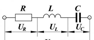
Element impedance
The total resistance of a capacitor (impedance) to an alternating signal is the sum of three components: capacitive, resistive and inductive reactance. All these quantities must be taken into account when designing circuits containing a storage element. Otherwise, in an electrical circuit, with appropriate wiring, the capacitor can behave like a choke and is in resonance.
Of all three quantities, the most significant is the capacitive reactance of the capacitor, but under certain circumstances the inductive reactance also has an effect. Often during calculations, parasitic values such as inductance or active resistance are assumed to be negligible, and the capacitor in this case is called ideal.
The impedance of the element is expressed in the formula Z = (R2 + (Xl-Xc) 2 ) ½, where
- Xl - inductance;
- Xс - capacity;
- R is the active component.
The latter arises due to the appearance of electromotive force (EMF) of self-induction. The inconstancy of the current leads to a change in the magnetic flux, which maintains the self-inductive emf current constant. This value is determined by the inductance L and the frequency of flowing charges W. Xl = wL = 2*p*f*L. Xc is capacitive reactance, depending on the storage capacity C and current frequency f. Xc = 1/wC = ½*p*f*C, where w is the circular frequency.
The difference between the capacitive and inductive values is called the reactance of the capacitor: X = Xl-Xc. According to the formulas, you can see that as the frequency f of the signal increases, the inductive value begins to dominate, and as it decreases, the capacitive value begins to dominate. Therefore if:
- X > 0, the element exhibits inductive properties;
- X = 0, only the active value is present in the container;
- X
Active resistance R is associated with power losses, the conversion of its electrical energy into thermal energy. Reactive - with the exchange of energy between alternating current and an electromagnetic field. Thus, the total resistance can be found using the formula Z = R + j*X, where j is the imaginary unit.
Element impedance.
Resistance measurement and calculation formula
The active resistance of the inductor can only be measured in a de-energized state. This is done using a multimeter.
- The multimeter must be switched to ohmmeter mode.
- Connect the red measuring probe to the first output of the coil.
- Connect the black test lead to the second output.
- The device will only show the active resistance of the winding.
Using a tester, you can only determine the integrity of the turns. If the element is connected to a live circuit, then the resistance value is found by a simple calculation using the formula: Z=U/I.
To calculate using this formula, using a tester, first determine the value of current (I) and voltage (U). Active resistance is measured in Ohms.
Knowing the formula for calculating active and inductive resistance, the total resistance of the element can be found using the formula:
Z=2×(R×R+XL×XL)
In this expression, R is resistance and XL is inductive.
Energy of the inductor.
Electric current flowing through the coil contributes to the accumulation of energy in the magnetic field of the coil. When the current is lost/switched off, this energy will be returned to the electrical circuit. This is what we encountered when considering inductors in DC circuits. There’s nothing more to add here, I’ll just give a formula that can be used to determine the amount of this accumulated energy:
W = \frac{LI^2}{2}
We are gradually moving on to options for connecting the coils to each other. We will perform all calculations for ideal inductors, that is, their active resistances are equal to 0. By the way, in most theoretical problems and examples, ideal coils are considered. But do not forget that in real circuits the active resistance is not equal to 0, and it must be taken into account when carrying out any calculations.