There is a DC motor. The task is to develop, assemble and test a device that allows the implementation of a current loop in relation to this motor. The desired transient time for a stopped motor (without back-EMF) is no more than 10 ms. The communication interface with the external control controller is SPI. DC motor, commutator, maximum voltage 24V, operating current up to 5A.
What does current loop mean? The most common drivers for controlling motors are all sorts of variations of half-bridges that amplify the voltage. But I want the driver to take current, not voltage, into the input. The force developed by the electric drive is directly proportional to the strength of the current flowing. This means that it is directly proportional to the acceleration on the engine shaft. Such a current circuit will allow you to avoid perversions that you need to go through without it, as I did here.
I have divided this text into two articles:
- 1. Motor resistance and inductance measurement
- 2. Development of the control circuit
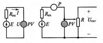
This is what the layout of the control hardware looks like:
The system will include:
- A power key chip that receives an input PWM signal and amplifies it.
- Current sensor.
- A control microcontroller that implements feedback and control law.
Current sensor and its testing
The Allegro ACS714 ($3) Hall sensor was selected as a current sensor, producing an analog signal centered at 2.5V and 185mV/A, typical error 1.5%.
An RC circuit was added to the sensor as a low pass filter with a cutoff frequency of 16kHz. The current sensor was powered from a 4.96V source; a resistor was connected in series with the sensor, through which 2A was passed. The theoretical voltage at the output pin should be 4.96/2 + (2 * 0.185 +- 1.5%), the measurement showed 2.84 V, which fits within the calculated parameters. Then the direction of current flow through the resistor was changed, at -2A the measured voltage at the output pin of the sensor was 2.11V, which again fits into the calculated parameters:
This check was necessary because... I bought several breadboards with ACS712 and ACS714 from different manufacturers, and only one was included in the datasheet parameters!
Specifics and features of three-phase networks
Three-phase electrical networks most efficiently transmit current through intermediate links, right up to the consumer. During the delivery process, energy losses are minimal.
The presence of a three-phase network in an apartment or private house is very easy to determine. To do this, you just need to look into the panel and count the number of wires. If there are 2 or 3 conductors, then the network is single-phase. There are two wires in it: phase and zero. If there is a ground, there may be a third wire. In three-phase networks there are two more wires due to the two additional phases. In the absence of grounding, there are only four of them, and in the presence of a grounding loop, there are five.
The same problem can be solved using an input circuit breaker. A certain number of wires are also supplied to it, connected to the appropriate terminals.
During the operation of a three-phase network, there is a high probability of uneven load distribution across individual phases. If only powerful equipment is connected to one of them, and ordinary household appliances are connected to the others, a situation called phase imbalance may arise. As a result of current and voltage asymmetry, individual consumers may fail. To avoid negative consequences, the load must be evenly planned at the design stage and the power of the three-phase network must be calculated.
A three-phase network, compared to a single-phase network, is distinguished by a large number of cables and wires, automatic devices and other devices. Specific three-phase equipment is connected to it. The total power will be exactly three times higher. The power value is calculated from current and voltage using formulas.
Microcontroller
ATMega328p, operating at a frequency of 16 MHz, was selected as the control microcontroller.
The microcontroller is connected to a Chinese clone of Arduino Nano v3 ($1.5). The microcontroller generates a PWM signal through an eight-bit counter with a divider of 8, so the frequency of the PWM signal is 16 * 10^6 /255 /8 = 7.8 kHz, which fits within the maximum 20 kHz available to the driver.
The microcontroller ADC divider is set to 128; Since each measurement requires approximately 13 clock cycles, the maximum frequency of current flow measurements is approximately 16 * 10^6 / 128 / 13 = 9.6 kHz. Measurements are made in the background, notifying the main program of completion by calling the appropriate interrupt.
Logs
I struggled for a long time with how to record what was happening inside the microcontroller, because it has very little memory.
As a result, I discovered that the native SPI interface is very fast, and as a result, all debugging information is transmitted by the microcontroller via the SPI interface; a widely available ($10 on Dilextreme, $6 on AliExpress) Chinese clone of the Saelae Pro 8 Logic logic analyzer was used to record it. After very simple manipulations of flashing VID/PID, it can be used with native software from Saelae. I use sigrok (pulseview). It has an extremely simple log file format, which I simply read with my homemade fifty-line program. I bought this analyzer on the advice of gbg, who repaired my Spectrum remotely for me (thank you very much!), and I consider it the best investment in the last two years. For example, I applied a sinusoidal signal (in PWM) to the output of the controller, and the logic analyzer sees it perfectly:
All this was put together, the photo is given in the title of the post.
Almost all the articles that I post here are my work diary. I learn something (in this case management theory) and diligently write down what I learn. The best way to write it down is to write an explanation of how it all works. Then I post the articles on different platforms, for example here.
I have two goals when writing text:
a) get feedback from people who know more than me.
For example, almost everything that I learned for these two articles was told to me by dear Arastas, please love and favor: a person who spends his personal time teaching idiots like me.
Again, gbg, who wrote me linear algebra for my computer graphics lectures, and then debugged the electronics for me over the phone many thousands of kilometers away.
b) just write:
This way I get a library of personal experience, which I return to periodically.
By the way, thematic media, what percentage of authors agree to your support program terms?
Fourier transform
The first thing you need to understand when reading my texts is that I believe that a function and a vector are the same thing.
All the talk about infinity bores me and obscures the essence of what is happening. Generalized functions and the like are a way of looking at pathological cases using the same language as cases where there is no pathology. It’s just that I’m not interested in pathologies. Valery Ivanovich Opoytsev (Boss) spoke well on this topic:
In any field, it is useful to be in a suitable environment of oral communication, where the bookish husks fall off.
Sometimes nothing changes in essence, but there is a feeling of falling into a rut and liberation from dogma. For science, which is always wearing a mask, this is especially important. The essence is behind the scenes, before the eyes - lace. And there is always something missing. Either simplicity, or complexity, but you can’t determine exactly what. Something is moving somewhere, you are on the sidelines, and time is disappearing into the sand, not to mention life. Next, an attempt is made to move the situation forward by simulating a writing environment where the “veils fall away.” The external outline of the content is more or less unclear from the table of contents, but the main goal is what is behind the scenes. Remove the veil, makeup, remove the decorations. Oversimplify, even lie a little, because dosing the truth is the cornerstone of explanation. The results, overloaded with details, do not fit where they should. The epiphany happens when the plump head falls to the level of “two times two”, while the count goes on in the millions. Such is the dialectic here.
If we have a vector (7,12,18,-2), then it can be considered as a set of coefficients in a weighted sum.
7*(1,0,0,0) + 12*(0,1,0,0) + 18*(0,0,1,0) + (-2)*(0,0,0,1) . In exactly the same way, we can consider this vector to be the values of the function at points 0, 1, 2, 3, because our vectors (0,1,0,0) and similar ones can be considered as a shift of a unit impulse: If we constantly increase the number of vectors (shifted unit impulses ) in the basis, we get the usual functions. Unfortunately, such a basis can be quite inconvenient to work with. Let's take the following function as an example:
We have already talked about what the Fourier transform is. In short, this is a change of basis.
In our case, the Fourier transform is a function from real numbers to complex numbers:
A function's argument (real number) is simply the number of the basis function or vector (actually, a pair of basis functions), and its value is the corresponding (pair of) coordinates in for those two vectors in the basis. The Fourier basis is the sines and cosines of various frequencies. The frequency is the number of the basis function.
For our specific function f(t), which is already a weighted sum of sine and cosine, it is very easy to calculate its expansion into a Fourier basis:
That is, our function f(t) has zero coordinates for all basis vectors, except for vectors number 11 and 41.
How is the Fourier basis useful? For example, because the differentiation operation linearly transforms this basis. Let's say we want to calculate the Fourier transform of the derivative f'(t). How to do it? As an option, straight forward: first calculate the derivative, and then calculate the Fourier transform:
Obviously, when differentiating sin(x), it will become sin(x+90°), that is, it is extremely easy to find a correspondence between the Fourier basis expansion of the original function and its derivative: Multiplication by
i
is simply a rotation of the complex plane, which corresponds to +90° in the argument of our function. That is, the differentiation operation, which is difficult to do in the basis of unit impulses, in the Fourier basis is simply scaling and rotating by 90 degrees. Beautiful, is not it?
Laplace transform
Approximately the same story happens with the Laplace transform.
Unfortunately, unlike the Fourier basis, the Laplace basis is non-orthogonal, and therefore is a little more complex for intuitive understanding. Well, that's not the point. Laplace went a little further. If Fourier had only sinusoids in his basis, then Laplace had sinusoids with exponential decay in his basis. Where did he get them from? This is extremely, extremely useful for solving linear differential equations. Let's think about what function transforms into itself upon differentiation? Exhibitor. What about differentiation twice? Sinus. And their combinations give all possible functions that can appear when solving (linear) diffuses, which is what the Marquis de Laplace used. We will not go into details of how these properties are derived (it’s better to carefully consider the properties of the Fourier basis, it is simpler), let’s just note the following facts:
1. Laplace transform is linear:
2. The Laplace transform of the derivative is an affine action on the transformation of the function itself: 3. So, if we have a DC motor, then the flowing current I(t) and the terminal voltage U(t) are related by the following differential equation, where w(t ) is the speed of rotation of the motor shaft: Here L is the inductance and R is the resistance, which is what we are looking for. I will not repeat where this diffuser comes from, since I have already described it in detail and on my fingers (see “Maxwell’s equations on my fingers”).
Since our task is to find L and R, let's rigidly fix the motor shaft, thus forcing w(t) to be zero:
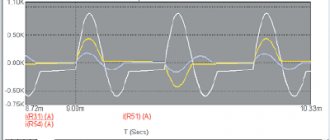
On the advice of Arastas, I supplied two types of signals to my engine: a square wave and a sine wave. Then I measured the current flowing, the picture looks something like this:
Here the blue traces are the input voltage that I am monitoring, and the green ones are the current measurements taken with the ACS714.
My microcontroller code, which generates 11 experiments with square waves and sinusoids of various amplitudes and frequencies, can be viewed here.
Let's solve our differential equation for both types of voltage signal, obtain a parametric current output, and adjust the parameters so that the theoretical curve approximates the actual measurements as best as possible.
Starting characteristics of asynchronous motors
Lecture 12. | Starting characteristics of asynchronousengines |
| 12.1 | General provisions |
electromagnetic waves arise in them.
and
electromechanical
transients.
electromechanical
are considered mainly , in which only the action of a steady current is analyzed. The reduced rotor current, at start-up, is almost equal to the stator current, and the starting torque are equal to:
;
.
It follows that limiting inrush currents is possible either by increasing the short-circuit impedance or by decreasing the magnitude of the applied voltage. The starting torque can only be increased to the maximum torque value:
,
which occurs if:
.
The starting torque can be increased either by influencing the critical slip or by reducing the rotation frequency of the stator field. Transient processes are accompanied by significant energy losses, which are many times higher than losses in the nominal operating mode, and cause increased heating of the windings. Since at start-up: , the total electrical losses will be equal to:
. (12.1)
Losses in the rotor will be determined through mechanical parameters:
, (12.2)
where the torque is determined from the general equation of motion of the drive, taking into account the moment of inertia and moment of resistance:
. (12.3)
To highlight the energy losses caused by the transient process itself, we assume that the moment of static resistance reduced to the motor shaft is equal to zero ,
what happens when starting at idle speed. Energy losses in the rotor during the transient process are determined by integrating power losses over time and, taking into account equations (12.2, 12.3), are determined as follows:
. (12.4)
Considering that: , we get:
;
. (12.5)
From the resulting expression it follows that when starting without load, energy losses during the transition process depend only on the total moment of inertia of the system, synchronous rotation speed w 1
, initial and final slips.
| 12.2 | Starting wound rotor motors |
Starting motors with a wound rotor is based on the introduction of additional active resistances into the rotor circuit, providing an increase in torque and a decrease in currents during the start-up. The amount of additional resistance that ensures maximum torque is calculated using the formula:
. (12.6)
The starting current decreases and is:
. (12.7)
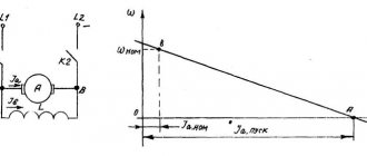
Typically, during the starting process, additional resistances are adjusted in steps, providing certain limits for the change in current and torque. When the torque is reduced to Mp. min
part of the starting rheostat (
r '21 ext
) is short-circuited, as a result the torque again increases to the maximum value, and the engine switches to a new characteristic. Ultimately, the starting rheostat is completely removed, and the engine returns to its natural characteristic. The number of stages is determined by the requirements for smooth starting, and the resistance values are found from the starting diagram (Fig. 12.1).
| 12.3. | Engines with double squirrel cage and with deep slot rotor |
Double squirrel cage engines
have two short-circuited rotor windings, one of which is working, and the second is starting. The working winding is made of copper rods of a relatively large cross-section, has low active resistance, and is located at a considerable depth from the rotor surface. The starting winding is made of materials with high active resistance (brass or bronze), its rods have a relatively small cross-section and are located near the rotor surface. There is a narrow gap between the rods of the working and starting squirrel cages (Fig. 12.2). As a result, the average length of the magnetic power lines along which the leakage fluxes of the working winding are closed is significantly less than for the leakage fluxes of the starting winding. Thus, the starting winding has a relatively small inductive leakage resistance, and the working winding has a relatively large one.
The currents in the working and starting squirrel cages are distributed inversely proportional to their impedances:
.
At the moment of starting, the frequency of the current in the rotor is high, the inductive resistances are many times higher than the active ones, and the distribution of currents is determined mainly by them, therefore, at the initial stage of starting, the current in the starting cell is greater than the current in the working cell:
; ; .
The starting winding has increased active resistance, and the critical slip for it is close to unity, so it creates a large starting torque.
As the rotor accelerates, slip and current frequency f 2
in it decrease, which leads to a decrease in inductive reactance. At the end of the start-up, they become significantly smaller than the active resistances, the ratio of which will mainly determine the distribution of currents. In this case, the current in the working winding becomes greater than the current in the starting winding:
; ; ,
and the engine will operate with low slip and high efficiency.
The resulting torque is determined by the summation of the torques created by the starting and working windings. In the area of large slips: it increases significantly compared to the moment created by a conventional squirrel cage (Fig. 12.2 - b).
Motors with deep-slotted rotor
have grooves in the magnetic system of the rotor, the height of which is 6 to 12 times greater than the width (Fig. 12.3). The short circuit winding is usually made by pouring aluminum or its alloys into these slots. The physical processes occurring in them during startup are in many ways similar to the processes in engines with a double squirrel cage. The role of the starting winding is played by the upper parts of the cross-section of the rods, for which the closure paths of the magnetic leakage fluxes are much longer than for the lower parts of the cross-section. At the moment of starting, the frequency of the current in the rotor is high, and the distribution of currents is determined mainly by inductive reactances. Since the inductance of the lower layers of a short-circuited winding is much greater than the inductance of its upper layers, therefore the current is displaced into the upper layers. As a result, the effective depth of current penetration and the effective cross-section of the conductors decrease, and the active resistance increases. This leads to an increase in critical slip and starting torque.
As the rotor accelerates, the slip and frequency in it decrease, which leads to a decrease in the influence of inductive reactances on the current distribution over the cross-section of the conductors. The effective penetration depth and the effective cross-section of the conductors increase, the current returns to the lower layers (Fig. 12.3). After acceleration is completed, the current density becomes almost the same over the entire cross section, the active resistance of the rods decreases, the engine operates with low slip and high efficiency.
rotor chains
.
Thus, active resistance r '2
in engines with a deep-slotted rotor it changes during acceleration. This does not affect the maximum torque, but does affect the critical slip and starting torque.
| 12.4. | Starting asynchronous motors by changing the rotation speed of the stator field |
It was previously shown that with a direct start in one stage, the losses in the rotor, regardless of other conditions, are equal to the reserve of kinetic energy of the inertial mass rotating with a frequency w 1 :.
An effective means of reducing losses is starting with a change in the synchronous speed. For example, when starting in two stages, we have the following initial data:
; ; ; ; .
Substituting these values into the original equation, we get:
.
Electrical losses in the rotor in each section are reduced by four times, and the total losses are reduced by half (Fig. 12.4).
When starting in four stages, they will be reduced by four times, and when starting in n
steps with equal increments: the total losses are:
(12.8)
and theoretically can be reduced to zero. In reality, this is impossible, since the transient time increases, which leads to an increase in no-load losses.
From equations (12.5), (12.8) it is clear that when assessing any transient processes, the most important role is played by the constant value of kinetic energy for a given engine. To assess the energy properties of transient processes, we introduce the concept of equivalent acceleration time, by which we mean the time during which the engine, having spent the same amount of energy as during a real idle start, would accelerate from a stationary state to a synchronous speed, if acceleration went with power losses equal to losses when operating with a rated load:
. (12.9)
Using this expression, you can evaluate the intrinsic energy properties of any electric motor. In Fig. Figure 12.5 shows how the equivalent acceleration time depends on the power and number of pole pairs of 4A series motors.
Taking into account the total moment of inertia of the electric drive during the transient process, it is possible to find the equivalent start-up time, taking into account specific conditions. By comparing this time with the operating cycle time, one can judge the feasibility of implementing controlled transient processes. This problem is most relevant for powerful engines with large inertial masses.
Reducing energy losses when starting asynchronous motors is achieved through the implementation of the following measures: reducing the total moment of inertia, organizing start-up without load; regulation of the rotation speed of the stator field.
| 12.5. | Low voltage starting |
Limiting the starting currents of asynchronous motors by reducing the voltage is used if the start is carried out without load. In this case, the current decreases in proportion to the voltage, and the torque is proportional to its square, that is, to a much greater extent. For example, when starting by switching the windings from star to triangle, the voltage and current are reduced by a factor, and the torque by a factor of three.
In general, start-up is ensured if the following condition is met:
, (12.10)
where µп
and
Mnom
– the starting torque multiplicity (given in the catalog data) and the rated torque of the electric motor;
– relative decrease in voltage; Мс0
– moment of static resistance when starting, reduced to the motor shaft; – the minimum excess torque required to ensure a successful start (usually taken equal to ).
From condition (12.10) you can determine the minimum voltage required for a successful start:
. (12.11)
The static drag torque, which significantly affects starting characteristics, is a function of rotational speed. The most severe starting conditions occur for constant torque characteristics: In the system of relative units: ; in this case we get:
. (12.12)
From this expression it follows that a reduction in voltage at start-up is possible only if the following condition is met for the starting torque multiplicity:
. (12.13)
The excess torque during starting under load does not remain constant, and depends on the law of change in the moment of resistance. From the characteristics shown in Fig. 12.6 - a, it is clear that with a fan moment of resistance, the moment M( U )
, developed by the engine at reduced voltage, is always greater than the moment of resistance, so the start will be successful, and the engine will operate stably at point
A
with a slight decrease in the steady-state values of rotation speed and torque.
With a constant torque characteristic (Fig. 12.6 - b), a decrease in voltage leads to the fact that in section B - At the
moment of resistance it exceeds the torque developed by the engine, and accelerating the engine to the point of steady-state operation under these conditions is impossible.
In such cases, it is necessary to ensure starting without load. For this purpose, special methods are used, which include blockages from blockages in automatic control systems, conveyors, the use of elastic links and accelerating couplings when connecting engines and working mechanisms, which provide traction with the load only after the engine has accelerated.
| 12.6. | Starting under conditions of comparable power |
Under operating conditions, direct starting of high-power asynchronous motors for power supply can cause significant voltage drops in a section of the network. This can lead not only to a violation of the conditions for a successful start (12.10 - 12.12), but also negatively affects the characteristics of other consumers connected in close electrical proximity.
Short-term voltage drops (dips) affect the performance of electrical receivers in different ways: within certain limits, they do not pose a danger to rotating electrical machines that have a sufficient supply of kinetic energy, but can cause magnetic starters to turn off, fluorescent lamps to go out, personal computers to malfunction, and disruption of the normal functioning of many other electrical receivers. Voltage dips are explained by a large increase in current and total power consumed by the motor from the network during startup. As was shown earlier, the secondary voltage of transformers depends not only on the magnitude, but also on the nature of the load, and its relative change is determined by the formula:
, (2.14)
where are the given values of secondary voltages in no-load and load modes; – load factor characterizing the current module; active and reactive components of the transformer short circuit voltage, o. e.; – phase angle of the load.
To identify some features of voltage changes when starting asynchronous motors, let’s write this expression in a form more convenient for analysis. Considering that the active and reactive components of the short circuit voltage are equal:
and the well-known formula for trigonometric transformations:
,
we get:
. (2.15)
Using this expression, we estimate the relative voltage losses during startup. The load factor at the moment of starting increases in proportion to the current, phase angle j 2
at a load close to the rated load, it is within the range: , and at start-up it is very close to the phase angle of the short circuit of the transformer
j to
: , i.e. From here it is easy to get the relation:
, (2.16)
from which it follows that with a multiplicity of the starting current kI
= (5 - 7
), the relative voltage losses caused by the starting currents can increase compared to the losses that occur at the rated current by 7 - 10 times. Given the limited power of the transformer and the network section to which the motor is connected, this leads to significant voltage drops at this point.
Electrical installation rules allow the voltage at the terminals of a starting asynchronous motor to be reduced by up to 30%, and at the terminals of running motors - up to 20%. To calculate the actual voltage reduction, it is necessary to know the configuration of the electrical network and the parameters of all its elements and loads. In Fig. Figure 2.17 shows a typical design diagram for networks of limited power.
Relative voltage value U *12
on the common buses of the started electric motor and the load connected to them, it is recommended to determine it using the formula:
, (2.17)
where z tr ,
z l
are the impedances of the transformer and power line;
z d
– short circuit resistance of the started electric motor;
z Н1 , z Н2
– load resistance.
In order to simplify the calculations and introduce a certain margin into their results, taking into account the ambiguity of the initial data, the impedance modules are arithmetically summed up in expression (2.17). If the loads are specified by currents, their resistances are determined by the formulas:
. (2.18)
The short circuit resistance of a started electric motor is calculated based on the rated values of voltage, current and starting current multiple, which are always given in the catalog data:
. (2.19)
Input signal - Heaviside function (half-wave square wave)
So, w(t) = 0, initial conditions I(0) = 0, the current does not flow at the very beginning.
If we apply a constant voltage U0 to the motor terminals, how should the flowing current behave? Let's take the Laplace transform from the left and right sides of the differential equation (1):
To get the second line, I used the linearity of the Laplace transform, U0/s - I took it from the table (usually Laplace transforms are not calculated manually, they use tables).
To obtain the third row, the derivative property was used.
The last line is obtained from the penultimate line using the method of indefinite decompositions. The point of this transition is to again obtain a table function. Of course, in the twenty-first century there is no need to count this with your hands.
Now it remains to apply the inverse Laplace transform (for the right side we look at the table) and we have solved our diffuser. The transition to the Laplace basis turned the differential equation into an ordinary algebraic one!
Quick check of the result: after a few milliseconds, the inductance will no longer play a role, and we will get a flowing current U_0 / R (Ohm's law). At the very beginning, the flowing current is zero and increases exponentially, and the rate of increase directly depends on the inductance. Sanity check passed.
The measurement file is here. Three columns, seconds, applied voltage (in volts), measured current (in amps).
Here is the code that selects the resistance and inductance parameters for this experiment:
Hidden text
import numpy as np from scipy.optimize import curve_fit import matplotlib.pyplot as plt U0 = 19.2 def unit_step_current(x, R, L): return [U0/R — U0/R*np.exp(-t*R/L) for t in x] data = np.genfromtxt('unit_step_19.2V.csv', delimiter=',', names=['t', 'V', 'A']) [R, L] = curve_fit(unit_step_current , data['t'], data['A'])[0] print(R, L) fig = plt.figure() ax1 = fig.add_subplot(1,1,1) ax1.set_title(“Resistance/ inductance fitting") ax1.set_xlabel('Time, seconds') ax1.set_ylabel('Current (A), tension (V)') ax1.plot(data['t'], data['V'], color= 'b', label='input tension') ax1.plot(data['t'], data['A'], color='g', label='measured current') model=unit_step_current(data['t '], R, L) ax1.plot(data['t'], model, color='r', label='fitted curve') ax1.legend() plt.show()
It says the pair fits well R=4.4 Ohm, L=6mHenry, here is the graph:
Measuring tool.
The measurement of each quantity should be repeated in different places so as not to fall into error due to the incorrectness of one measurement.
The internal diameter of the stator or, as is often said, the diameter of its bore D is one of the most important dimensions of the engine; Since the correct determination of other dimensions depends on the size of the stator core and the accuracy of its measurement, it must be done as carefully as possible.
The best tool for this is an internal micrometer (microscopic shtihmas); with its help you can measure the diameter of the bore anywhere.
Typically, such gauges are made for measurements from 50 to 63 or 70 mm; They are equipped with sets of extension attachments that allow you to expand the micrometer gauge with a measurement accuracy of up to several hundredths of a millimeter. If this tool is not available, then for diameters up to 200 - 250 mm you can use a caliper; however, this is not always possible, since often the stator core sits so deep in the housing that the caliper jaws do not grip it. In such cases, measurements can be made using an ordinary gauge made from a piece of steel wire; After adjusting such a gauge to the diameter of the bore, its length is measured with a caliper.
For diameters greater than 250 - 300 mm, you can also use an ordinary metalworker's caliper with a scale ruler, although this is much less accurate.
When measuring the internal diameter, you need to ensure that it is taken between the middles of two opposite teeth, since the edges of the teeth may be somewhat tucked inside the groove.
Measured values.
The outer diameter of the stator Dн cannot always be measured directly; the measurement is easiest if the stator core is pressed into the housing without any space between them, as is usually done in closed motors; then you can simply measure the diameter of the housing bore. If the stator core sits in the housing on legs that form part of the core itself, or are not flush to the housing, then the measurement may be prevented by pressure rings compressing the core. Usually their outer diameter is approximately equal to the outer diameter of the stator, but they often do not sit quite exactly in place, with some offset that prevents the caliper jaws from properly gripping the stator. Then you can do this: instead of measuring the diameter, measure the height of the stator along with the teeth in the direction of the radius using a caliper, inserting one of its jaws into the gap between the stator core and the housing, and so that the shifted pressure ring ends up in the cutout that is usually provided with the jaws of the caliper at its base. If we denote the stator thickness measured in this way as hc, then the outer diameter will be equal to:
DH = D + 2hc (cm)
The height of the stator body hs, if there is a gap between the stator core and the housing, is measured in the same way as the value hc; if there is a gap between the stator cores and the housing, it is measured in the same way as the value hc. If there is no gap, then it is obtained by calculation from other quantities (see below).
The length of the stator core in the axial direction ln is not a very strictly defined value; therefore, its measurement can be done either by measuring the axial length of the stator with a caliper or with a simple scale ruler. However, it should never be measured at the heads of the teeth, because the teeth at the ends always diverge somewhat to the sides, forming a so-called “fan”. The correct value is obtained by measuring this value along the bottom of the groove.
The total number of stator slots Z is determined by the count; it is always divisible by 3 and usually even.
The dimensions of the stator slots and teeth to be measured depend on their shape. The grooves differ:
- open; with a hole width equal to the groove width;
- semi-closed, having a hole with a width less than the width of the groove;
- closed, having no opening at all.
Open grooves, characteristic of modern more or less large machines, are always rectangular in shape and are equipped with shoulders at the hole for installing a wedge; They are subject to measurement: width, full depth and depth below the shoulders.
Semi-closed grooves have much more variety in shape, which should be measured. Here we can give only some general instructions for this most painstaking part of the measurement.
- Impression method; Take two plates of sheet lead 2-3 mm thick, such that each of them can cover two or three grooves. To obtain an impression, these plates are placed on the end of the core at the ends of some of its diameters and covered with a massive strip with a hole in the middle. Another similar strip is located on the opposite side of the core; a bolt is passed through the holes in both strips. By tightening the nut, the lead is pressed into the grooves and receives their impression, which is then carefully measured using a caliper with sharp jaws or a drawing compass and decimal scale. Instead of lead, soft, but not laminated cardboard can be used. Taking an impression by hitting a lead plate with a hammer through a gasket is not recommended, since the impression will be knocked down and inaccurate.
- Wedge-shaped feeler method: two steel scales, 150 mm long and 20 mm wide, are cut obliquely like this. Wedge-shaped probes; two wedge-shaped probes are obtained, one of which serves to measure from 1 to 15 mm, and the other from 10 to 20 mm.
Input signal - sine
Let's repeat the procedure for a voltage sinusoid with amplitude U0 and frequency F0.
Let's apply the Laplace transform to equation (1), first to the right side: and then to the left: Now the inverse transformation will give us the following law of current flow: Again, a quick sanity check: zero current at the very beginning, a few milliseconds of transient processes (an exponential directly dependent from inductance). After some time, the current flowing is the weighted sum of the sine and cosine of the same frequency (the frequency is equal to the input, this is good). This sum gives a sinusoid slightly shifted in time. Great, the result is plausible. The measurements are here, and the code for selecting parameters is here. It gives approximately the same values of resistance and inductance, which is what we needed. Here's the chart:
Why not measure the parameters directly, why all this garden with microcontrollers? Firstly, I have nothing to measure inductance with. Yes, and measuring engine resistance with an ohmmeter can have its own nuances.
Further, the parameters found at high signal amplitude do not exactly coincide with what is obtained at low voltages. It may be interesting (not discussed here) to make a model not only of the motor, but of the entire system as a whole, including the nonlinearity of the PWM driver.
Well, then all that remains is to develop a regulator that will take the required current at the input. Stay in touch!
How to calculate the power of an electric motor
How to calculate the power consumption of an asynchronous electric motor from the network if you can only find out the rated power from the nameplates? To do this you need:
- pay attention to the remaining indicators - these are η and cosφ (efficiency and power factor);
- take into account the relationship between the dynamic characteristics of the shaft and efficiency.
According to available data, it is possible to calculate the consumed electrical power:
P з=Р/η.
But we must remember that the energy consumed by electrical appliances includes both active and reactive components.