1. Arrester, its purpose, principle of operation
Arresters are protective devices. They are designed to protect the insulation of electrical equipment from overvoltages. The arrester consists of two electrodes and an arc extinguishing device.
One of the electrodes is fixed to the protected circuit, the second electrode is grounded. The space between these two electrodes is called the spark gap. At a certain voltage value between the electrodes, the spark gap breaks through and removes the overvoltage from the protected section of the circuit.
After a breakdown by a pulse, the spark gap becomes sufficiently ionized so that the phase voltages of the normal mode can break through, and therefore a short circuit occurs. The task of the arc extinguishing device is to eliminate this in the shortest possible time before the protection devices operate.
Operating principle of arresters. The design of the arresters provides an air gap in the jumper, which connects the phases of the power line and the grounding loop. At the nominal voltage value, the circuit in the jumper is broken. In the event of a lightning discharge as a result of overvoltage in the power line, a breakdown of the air gap occurs, the circuit between the phase and the ground is closed, and the high voltage pulse goes directly into the ground.
Types of arresters
Tubular arrester
Made in the form of a polyvinyl chloride tube designed to extinguish the arc. There is one electrode at each end of the spark gap. One electrode is grounded, and the other is installed at a short distance from the protected area.
This distance is adjusted depending on the voltage in the area. In the event of an overvoltage, a breakdown occurs in two places at once - between both electrodes and between the arrester and the protected area. The breakdown action leads to intense gas generation in the tube, and the longitudinal blast formed in the exhaust hole is quite capable of extinguishing the electric arc.
Valve arrester
The design includes two main parts: a multiple spark gap, consisting of several single elements, and a working resistor, which is a series of vilitic disks. Both main elements are connected in series. The working resistor is provided with hermetically sealed protection from the external environment, due to the properties of the vili it changes its characteristics at high humidity. When an overvoltage occurs, a breakdown of a multiple spark gap occurs.
The working resistor performs the task of reducing the current to such a value that the spark gaps can easily extinguish it. Vilit resistance is non-linear, it decreases as the current increases. This property makes it possible to pass more current while reducing the voltage drop. The main advantage of this type of arrester is considered to be silent operation in the absence of gas or flame emissions.
Magnetic valve arrester
It consists of several blocks connected in series, with magnetic spark gaps and vilitic disks. Each block contains single spark gaps connected in series and permanent magnets. All elements of the block are placed in a porcelain cylinder. During a breakdown, an arc occurs in single gaps. It is influenced by the field created by the ring magnets, causing it to rotate at high speed. As a result, arc extinguishing occurs much faster than in other types of valve-type arresters.
Gas arrester
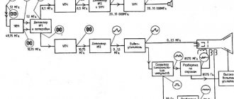
Gas arresters are components filled with an inert gas (Fig. 2). The arrester body is made in the form of a ceramic tube, the ends of which are closed with metal plates and act as electrodes.
Figure 2 – Block diagram of a gas discharger
Operating principle of the arrester
The principle of operation of the arrester is quite simple, as is its design. When an overvoltage occurs on the electrodes of the arrester, the voltage increases significantly. If this voltage becomes greater than the breakdown voltage, which is specified in the device characteristics, then a breakdown will occur.
A spark will jump between the electrodes. At the same time, the voltage on its electrodes will decrease, and the air in the spark gap will be ionized. The arrester will be pierced by phase voltage and a short circuit will occur.
To prevent this from happening, there is an arc extinguishing device in the arrester. Depending on the type of arrester, there are different types of arc extinguishing devices. All arresters are divided into several types.
Below are the main types of arresters.
Types of arresters:
-Tubular (air);
-Gas;
-Valve;
- Magnetic valve arrester (RVMG);
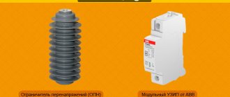
-Nonlinear overvoltage limiter (OSN);
-Tubular arresters (air)
Selection of arresters
The main parameters of arresters: capacity class, longest permissible operating voltage, levels of remaining voltages during switching and lightning impulses, rated voltage, magnitude of the response current of the anti-explosion device, rated discharge current, leakage distance of external insulation.
The choice of arresters is made based on the purpose, design, required level of overvoltage limitation, network diagram and its parameters.
Magnetic valve arrester (RVMG)
Unlike the valve arrester device, the magnetic valve arrester device includes a set of ring magnets.
The principle of operation of a magnetic valve arrester is slightly different. When a phase voltage breaks down, an arc is formed. Under the influence of the magnetic field of the magnets, the arc begins to rotate, thereby extinguishing the arc.
Figure 5. Magnetic valve arrester (VMG)
9. Technical characteristics of arresters
The following main technical characteristics of arresters are distinguished:
- Circuit voltage class;
- Highest permissible voltage;
- Breakdown voltage at a frequency of 50 Hz in dry conditions and in the rain;
- Pulse breakdown voltage at pre-discharge time from 2 to 20 μs;
- Remaining voltage at 8 µs wave;
- Leakage current;
- Current carrying capacity;
- Creepage distance of external insulation;
- Permissible wire tension;
- Height;
- Limiter weight.
What is a spark gap?
A surge arrester is a device that protects modern electronics from high voltage surges.
With the high development of industry, it was possible to make arresters economical and effective for use for their purposes. Nowadays, using reliable insulation is very expensive and ineffective; it is most convenient, of course, to use arresters.
In a narrow sense, arresters are protective elements of electrical circuits, without which electrical devices and the insulation of power line cables or wires would often deteriorate.
11. Arresters 6 kV, 10 kV, 35 kV, 110 kV, 220 kV
The main characteristics of 6-220 kV arresters are given in tables 2 and 3.
Table 2 - Technical characteristics of 6 kV, 10 kV arresters
| Parameter | Unit | RVO-6 N | RVO-10 N |
| Mains voltage class | kV | 6 | 10 |
| Highest permissible voltage | kV | 7,5 | 12,7 |
| Breakdown voltage at a frequency of 50 Hz in dry conditions and in the rain: | |||
| no less | kV | 16 | 26 |
| no more | kV | 19 | 30,5 |
| Pulse breakdown voltage at pre-discharge time from 2 to 20 μs, no more | kV | 32 | 48 |
| Remaining voltage at a wave of 8 μs, no more: | |||
| with current amplitude 3000A | kV | 25 | 43 |
| with current amplitude 5000A | kV | 27 | 45 |
| Leakage current, no more | µA | 6 | 6 |
| Current carrying capacity: | |||
| 20 current pulses with a wave of 16/40 µs | kA | 5,0 | 5,0 |
| 20 square wave current pulses with a duration of 2000 µs | A | 75 | 75 |
| Leakage distance of external insulation, not less | cm | 18 | 26 |
| Permissible wire tension, not less | N | 300 | 300 |
| Height, no more | mm | 294 | 411 |
| Weight, no more | kg | 3,1 | 4,2 |
Table 3 - Technical characteristics of 35 kV, 110 kV, 220 kV arresters
| Parameter | Unit | RVS-35 RVS-35 T1 | RVS-110M RVS-110M T1 | RVS-220M RVS-220M T1 |
| Mains voltage class | kV | 35 | 110 | 220 |
| Highest permissible voltage | kV | 40,5 | ||
| Breakdown voltage at a frequency of 50 Hz in dry conditions and in the rain: | ||||
| no less | kV | 78 | 200 | 400 |
| no more | kV | 98 | 250 | 500 |
| Pulse breakdown voltage at pre-discharge time from 2 to 20 μs, no more | kV | 125 | 285 | 530 |
| Remaining voltage at a wave of 8 μs, no more: | ||||
| with current amplitude 3000A | kV | 125 | 315 | 630 |
| with current amplitude 5000A | kV | 130 | 335 | 670 |
| Leakage current, no more | µA | 143 | 367 | 734 |
| Current carrying capacity: | ||||
| 20 current pulses with a wave of 16/40 µs | kA | 10,0 | 10,0 | 10,0 |
| 20 square wave current pulses with a duration of 2000 µs | A | 150 | 150 | 150 |
| Leakage distance of external insulation, not less | cm | 115 | 345 | 690 |
| Permissible wire tension, not less | N | 300 | 500 | 500 |
| Height, no more | mm | 1280 | 3100 | 4620 |
| Weight, no more | kg | 73 | 175 | 497 |
Tubular arrester
The tubular arrester is a tube made of durable material. The material itself is various polymers. The most common of them is polyvinyl chloride. PVC is able to withstand temperatures suitable for this type of arrester.
Two electrodes are placed in the tube (Fig. 1). One is connected to the protected element, and the other is grounded. The operating principle of a tubular arrester is quite simple.
When the breakdown voltage occurs, a spark is formed, which ionizes the air. The air becomes very hot and gases are released on a massive scale.
Intense gas generation extinguishes the phase voltage arc. This arc extinguishing device is called longitudinal blast. To allow gases to escape outside, there is a hole in the arrester.
A gas spark gap differs from an air spark gap only in that its body is filled with an inert gas (argon or neon). Unlike an air spark gap, in a gas spark gap the arc formed by phase voltage is extinguished by inert gases.
In modern electronics, tubular arresters are ubiquitous. They are simple in design and reliable. The breakdown voltage of air dischargers is low, so such arresters are not used in higher voltage equipment.
Higher breakdown voltage for gas arresters. They are much more efficient, since gases do not react, thereby extending the life of the electrodes.
▍Act seven. We spoil everything by forgetting about the little things.
The above is relevant for a spherical horse in a vacuum.
In real life there are a huge number of subtleties that are omitted for the sake of simplicity, but sooner or later they will make themselves felt. Here are examples of some of them: 1. Self-inductance and resistance of conductors.
A 1 meter long piece of wire has an inductance of approximately 1 μH and non-zero resistance. This means that at high rates of current growth (and they are typical for lightning), an extra supply of wire can reduce the meaning of protection to zero. Many manufacturers clearly indicate in their manuals that the length of the conductors from the line to the terminals of the protection device should be as short as possible, and in total not exceed 0.5 m. Here is a visual picture from the OBO BETTERMANN manual of how an extra 2 meters of wire affected the protection. If the SPD (orange) cuts the incoming pulse to a value of 1.5 kV, then an additional 2 kV drops on the conductors, and as a result, a pulse with a voltage of 3.5 kV will arrive at the load.
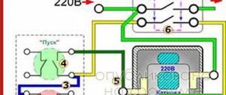
A very elegant way to reduce the influence of conductors is to connect like this:
Some manufacturers, for ease of installation, generally provide double terminals, for example, as on this device (domestic, by the way):
2. Resistance plays a role.
With a lightning discharge current of 50 kA, a voltage difference of 5 kV will be created on a conductor with a resistance of 0.1 Ohm when the current flows. Therefore, the SPD should be connected with the thickest possible conductor, at least 6 mm2, even if the line itself is 2.5 or even 1.5 mm2. If you connected the SPD in a V-shape as in the photo above, then only the grounding conductor will remain thick.
3. It is useless to connect protection devices in parallel without coordination.
The thought may creep in that if we install several protection devices in parallel, we will get Megaprotection. But it doesn't work that way. When an impulse arrives along the line, one person will act first and take the entire blow. In order for the cascade of protections to work consistently, and, as necessary, more and more powerful devices are connected to pulse absorption, they must be coordinated with special chokes. But since calculating such a cascade is not an easy task, it is extremely difficult to find matching devices in the catalogs of SPD manufacturers. The manufacturer began to produce combined devices, coordinating them internally. That is, instead of installing a II and III class SPD next to each other, you need to take a ready-made class II+III device.
4. We install an automatic machine instead of a fuse.
If you carefully read the documentation for surge protection devices, many manufacturers require the installation of fuses to protect against short circuits - if the device fails, it can short circuit the protected line to ground. And in this scenario, it is better if the fuse blows and disconnects the protection device from the line than if the input circuit breaker does this and de-energizes the load. But see point 1 - it is stupid to first achieve the minimum inductance of the conductors, and then plug in a circuit breaker, inside of which there is an electromagnetic release in the form of an inductance coil. As a result, the circuit breaker will work as an additional virtual few meters of wire (see point 1) increasing the voltage of the pulse reaching the load. And that is why it is highly advisable to use fuses. (this is without taking into account that there is a danger that a current pulse of 10-50-100 kA will cause sintering of the contacts in the machine)
5. SPDs based on varistors have leakage current.
It is small, but not zero. And here common sense takes a backseat to the power grid company, which has its own opinion on where the SPD should be installed. So it may turn out that you install the SPD after the meter. But since the meter is the property of the electric grid company, you can put on a cool face when the meter burns out after a thunderstorm and they come to replace it.
6. Lack of control.
Imagine that you have equipped an electrical panel with surge protectors that powers a weather station in a deserted place. A thunderstorm passed nearby, the SPDs fulfilled their function, saved the station’s contents from damage, but died themselves - they were turned off by the protection. And we get a situation where the station works normally, but at the same time has no protection, and the next thunderstorm can put it out of action. It is precisely from such unpleasant situations that there are SPDs with contacts that open/close when the protection fails (for example, in the photo of SPD-220 these are contacts 4 and 5). In this case, the deceased SPD can send a signal to the dispatch system that it is time to send an installer to replace the protection.
Selection and Application
The main purpose of using a surge arrester is to select the device with the lowest overvoltage threshold that will provide adequate equipment insulation protection and, when connected to the power system, have a satisfactory rated life. It is worth giving preference to arresters with a minimum operating threshold, since they provide the highest level of equipment insulation protection. There is a fine line between the degree of protection and the lifespan of a surge suppressor. A high response threshold will increase the service life of the arrester in a particular power plant, but will reduce the degree of protection of the equipment insulation. Thus, when choosing a surge suppressor, the reader needs to take into account both points - the service life of the surge arrester and the safety of the equipment.
It is best to install the arrester as close as possible to the equipment being protected, preferably in a auxiliary distribution panel. This requirement is based on the mathematics of wave theory, according to which the incident and reflected waves are directed to a nodal point (or shield room of the protected equipment). The length of wires for grounding the connection of surge suppressors to equipment terminals should be minimal. Wires must be laid straight, avoiding bends if possible. This ensures that the burst of energy goes into the ground along the shortest path. Increasing the length of the wire will reduce the protective ability of the surge suppressor due to the additional resistance in the wire.
To select the correct surge suppressor for the application conditions, the following key points must be taken into account:
- Constant mains voltage
- Temporary overvoltages
- Switching overvoltages (most often taken into account for capacitor banks, cables, as well as for transmitting voltages of 345 kW and above)
- Lightning surges
- *System configuration (grounded or ungrounded/grounded with isolated neutral)
Table 1 shows the arrester response levels typically used for systems with different line voltages. The capacity of the arrester is determined by the rms voltage at which it has passed the duty cycle test, as specified in the relevant standard.
| Table 1 Typical arrester response levels for various mains voltages | |||||
| Arrester response level (kV) | Arrester response level (kV) | ||||
| Rated network voltage (kV) | Network with grounded neutral | Network with isolated or compensated neutral | Rated network voltage (kV) | Network with grounded neutral | Network with isolated or compensated neutral |
| 2.4 | 2.7 | 3.0 | 69 | 54 | |
| 60 | |||||
| 4.16 | 3.0 | 66 | |||
| 4.5 | 4.5 | 72 | |||
| 5.1 | 115 | 90 | |||
| 4.8 | 4.5 | 96 | |||
| 5 1 | 6.0 | 108 | 120 | ||
| 138 | 108 | ||||
| 6.9 | 6.0 | 120 | |||
| 75 | 132 | ||||
| 8.5 | 144 | ||||
| 12.47 | 9.0 | 161 | 120 | ||
| 10 | 132 | ||||
| 12 | 144 | 144 | |||
| 15 | 168 | ||||
| 13.2, 13.8 | 10 | 230 | 172 | ||
| 12 | 180 | ||||
| — | 15 | 192 | |||
| 18 | 228 | ||||
| 23, 24.94 | 18 | 240 | |||
| 21 | 345 | 258 | |||
| 24 | 24 | 264 | |||
| 27 | 276 | ||||
| 34.5 | 27 | 288 | 288 | ||
| 30 | 294 | 294 | |||
| — | 36 | 300 | 300 | ||
| 39 | 312 | 312 | |||
| 46 | 39 | 400 | 300 | ||
| — | 48 | 312 | |||
| 336 | |||||
| 360 | |||||
Conditional graphic designations in schemes. Arresters. Circuit breakers
GOST 2.727-68
UDC 62(084.11):006.354
Group T52
INTERSTATE STANDARD
Unified system of design documentation
CONDITIONAL GRAPHIC DESIGNATIONS IN SCHEMES. Arresters; circuit breakers
Unified system for design documentation. Graphic identifications in schemes. Yaps, arresters and vases
Date of introduction 01/01/71
INFORMATION DATA
1. DEVELOPED AND INTRODUCED by the Committee of Standards, Measures and Measuring Instruments under the Council of Ministers of the USSR;
2. APPROVED AND ENTERED INTO EFFECT by Resolution of the Committee of Standards, Measures and Measuring Instruments under the Council of Ministers of the USSR dated 08/13/68 No. 1289;
3. INSTEAD OF GOST 7624-62 regarding section. 7;
4. EDITION (May 2002) with Amendments No. 1, 2, approved in December 1980, October 1993 (IUS 3-81, 5-94);
This standard applies to manual or automated circuits of products from all industries and construction and establishes graphical symbols for arresters and fuses.
(Changed edition, Amendment No. 1, 2)
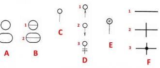
1. Designations of elements of electric vacuum devices - according to GOST 2.731-81. 2. Designations of protective and test arresters are given in table. 1. 3. Designations of high-frequency arresters are given in table. 2.
2, 3. (Changed edition, Amendment No. 1)
4. Designations of fuses are given in table. 3.
(Changed edition, Amendment No. 2)
Table 1
| Name | Designation |
| 1. Spark gap: a) two-electrode. General designation | |
| b) two-electrode symmetrical | |
| c) three-electrode | |
| 2. Discharger. General designation. Note: if it is necessary to clarify the type of arrester, then the following designations are used: | |
| a) tubular arrester | |
| b) valve and magnetic valve arresters | |
| c) ball arrester | |
| d) horn arrester | |
| e) carbon arrester | |
| f) electrochemical spark gap | |
| Note to paragraphs. c - e. It is allowed to enclose symbols in a rectangle | |
| g) vacuum arrester | |
| h) two-electrode ion spark gap with gas filling | |
| i) controlled ion arrester | |
| j) ball spark gap with igniting electrode | |
| l) symmetrical arrester with gas filling | |
| m) three-electrode spark gap with gas filling | |
| 1. Narrowband arrester: a) with an external resonator | |
| b) with an internal resonator; Note: when designating a reconfigurable arrester, the setting designation (arrow) is indicated on the image of the element by which the setting is carried out, for example: | |
| adjustment is carried out by changing the size of the discharge gap of the arrester | |
| tuning is carried out by a resonator | |
| 2. Inclusion of a narrow-band spark gap in the waveguide: a) coupling through the coupling hole | |
| b) communication through a communication loop | |
| 3. Broadband arrester: a) receiver protection | |
| b) blocking the transmitter | |
| c) preliminary protection of the receiver | |
| 4. Double arrester: a) receiver protection | |
| b) transmitter blocking | |
Table 3
| Name | Designation |
| 1. Breakout fuse | |
| 2. The fuse is hot. General designation | |
| Note: it is allowed to indicate the side that remains energized in the fuse designation with a thick line | |
| 3. Fuse: a) slow-fuse | |
| b) refractory | |
| c) fast-acting | |
| 4. Thermal (safety) coil | |
| 5. Fuse with signaling device: a) with independent signaling circuit | |
| b) with a common signaling circuit | |
| c) without indicating the signaling circuit | |
| 6. Switch-fuse | |
| 7. Disconnector-fuse | |
| 8. Three-phase switch with automatic shutdown by any of the impact fuses | |
| 9. Switch-disconnector (with fuse) | |
| 10. Impact fuse: a) general designation | |
| b) with a three-pin alarm contact | |
| c) with an independent signaling circuit |
▍Act five. Zone defense concept.
Is it possible to install a universal surge protection device in the electrical panel at the entrance to the house and not have any problems?
Unfortunately no. If only because even if you suppressed all unwanted surges at the entrance to the house, you can re-catch them with the wiring inside the building, for example, when the lightning discharge current follows from the lightning rod into the ground somewhere behind the wall - the electromagnetic field is so powerful that in any conductor will induce a current pulse. Or, for example, that the impulse will re-enter the network through the telephone, arriving along the telephone line. Therefore, the process of building protection becomes more complicated - it is necessary to analyze all the ways of penetration of an electromagnetic pulse from lightning into the protected object. In order not to install on each device a complete set of devices for protection against direct lightning strikes (it would be too expensive), they came up with the concept of zonal protection and corresponding classes of devices. An object, the electrical content of which is protected from lightning damage, is divided into zones according to the degree of lightning exposure. All lines (power, communications) passing from zone to zone are equipped with protection devices at the zone boundaries. It's easier to understand this with an abstract example of a house:
Picture taken from OBO Betterman manual.
Lightning protection guide (LPZ - lightning protection zone - lightning protection zone) Zone 0a is the zone where lightning can directly strike. The conductor may contain the full lightning current. Zone 0b is a zone where lightning will not directly strike, but the conductor may contain a partial lightning current, either due to the electromagnetic field or simply due to an insulation breakdown. Zone 1 - This is the zone where lightning-induced current can occur. Zone 2,3,4, etc. - a zone where the lightning-induced current is weakened and less than in the higher zone. There can be as many zones as you like, like in a nesting doll.
That is, it is clear - when moving from zone to zone, the electromagnetic pulse of lightning weakens, including due to protection devices at the borders
zones, and due to shielding and attenuation in space. For example, a concrete wall with grounded reinforcement inside can serve as such a screen. Zones are usually divided by natural obstacles - a wall, cabinet body, device body, etc.
And for convenience, protection devices are divided into classes. And when the division into zones is clear, it is enough to take a device of the corresponding class from the catalog. Class I (B) are devices capable of withstanding partial lightning current (zone 0), and are intended for installation on the input panel. (where zone 0 goes into zone 1) Class II (C) - these are devices that can withstand less current than a Class I device, but they are cheaper and the voltage to which they cut the pulse is less. Designed for installation on a distribution board. (Just where zone 1 turns into zone 2) Class III- (D) These are devices that can withstand an even smaller impulse than class II, but cut off the impulse almost completely. And they are designed for installation on the end user’s switchboard. Many well-designed devices have similar protection already inside them.
Why not put Class I protection devices everywhere? But simply because installing a class I device where class III is more than enough, for example, for the end consumer, is an unjustified budget overrun. It's like building a fully equipped fire station where you only need to install a fire extinguisher. In addition, the more brutal and powerful the protection device, the greater the magnitude of the pulse voltage that leaks through it to the consumer. (the higher the limiting voltage, see the picture above)
Picture from the Schneider electrician manual
But if you want everything at once, there are combined devices, for example Class I+II, which correspond to the parameters of several classes at once, but for such versatility the manufacturer will ask for additional money.
Constant mains voltage
When surge suppressors are connected to the power system, they are constantly exposed to operating voltage. Depending on the characteristics of the arrester, there are different limits for the DC voltage level. This is called the maximum continuous operating voltage (MCOV) of the arrester. It is necessary to select a surge suppressor with such characteristics that the maximum continuous voltage in the power system where the device will be installed is equal to or lower than the MCOV of the arrester. Both the power supply configuration (star or delta) and the type of arrester connection (line or phase) must be taken into account. In most cases, surge suppressors have a phase-to-ground connection. If the device has a linear connection, you should pay attention to the phase-to-phase voltage. In addition, to determine the optimal arrester parameters, it is also necessary to take into account the system grounding configuration - solid grounding or effective grounding (resistive grounding, temporary grounding, no grounding). This is a key factor in the selection and application of a surge suppressor. If the system grounding configuration is unknown, the reader should assume that the system is not grounded. In this case, it is worth choosing a surge arrester with a higher DC line voltage and/or MCOV level. It is also necessary to pay special attention to special areas of application of the arrester, such as the tertiary winding of a transformer, where one of the corners of the triangle is permanently grounded. In this case, the normal voltage constantly applied to the arrester will be completely linear, even if the surge suppressor has a phase-to-ground connection.
Examples of some of the maximum continuous operating voltage ratings for General Electric's TRANQUELL® polymer arresters are noted in Table 2 below.
| TRANQUELL® polymer arresters | |||||||||
| 8/20 µs Maximum discharge voltage - kV peak | |||||||||
| Rated voltage kVirms | MKOV kVirms | 0.5 µs 10 kA max IR-kV peak | Switching maximum overvoltage IR-kV peak | 1.5 kA | 3 kA | 5 kA | 10 kA | 20 kA | 40 kA |
| 3 | 2.55 | 8.4 | 6.0 | 6.4 | 6.7 | 7.1 | 7.6 | 8.4 | 9.6 |
| 6 | 5.10 | 16.7 | 11.9 | 12.8 | 13.5 | 14.1 | 15.2 | 16.8 | 19.1 |
| 9 | 7.65 | 25.0 | 17.8 | 19.2 | 20.2 | 21.1 | 22.7 | 25.1 | 28.3 |
| 10 | 8.40 | 27.8 | 19.8 | 21.4 | 22.5 | 23.5 | 25.3 | 28.0 | 31.8 |
| 12 | 10.2 | 33.3 | 23.7 | 25.6 | 26.9 | 28.1 | 30.3 | 33.5 | 38.1 |
| 15 | 12.7 | 41.7 | 29.7 | 32.0 | 33.7 | 35.2 | 37.9 | 42.0 | 47.6 |
| 18 | 15.3 | 50.1 | 35.6 | 38.4 | 40.4 | 42.3 | 45.5 | 50.0 | 57.2 |
| 21 | 17.0 | 56.3 | 40.1 | 43.2 | 45.5 | 47.6 | 51.2 | 56.7 | 64.4 |
| 24 | 19.5 | 63.9 | 45.5 | 49.1 | 51.6 | 54.0 | 58.1 | 64.3 | 73.0 |
| 27 | 22.0 | 72.9 | 51.9 | 56.0 | 58.9 | 61.6 | 66.3 | 73.4 | 83.3 |
| 30 | 24.4 | 80.4 | 57.2 | 61.7 | 64.9 | 67.9 | 73.1 | 80.9 | 91.9 |
| 36 | 29.0 | 95.9 | 68.3 | 73.6 | 77.4 | 81.0 | 87.2 | 96.5 | 109.6 |
| 39 | 31.5 | 104.2 | 74.2 | 80.0 | 84.1 | 88.0 | 94.7 | 104.8 | 119.0 |
| 45 | 36.5 | 120.9 | 86.1 | 92.8 | 97.6 | 102.1 | 109.9 | 121.7 | 138.1 |
| 48 | 39.0 | 128.7 | 91.6 | 98.8 | 103.9 | 108.7 | 117.0 | 129.5 | 147.1 |
| 54 | 42.0 | 144.4 | 102.8 | 110.9 | 116.6 | 122.0 | 131.3 | 145.3 | 165.0 |
| 60 | 48.0 | 163.5 | 116.4 | 125.5 | 132.0 | 138.0 | 148.6 | 164.5 | 186.8 |
| 66 | 53.0 | 179.9 | 128.0 | 138.1 | 145.2 | 151.8 | 163.5 | 181.0 | 205.5 |
| 72 | 57.0 | 191.8 | 136.6 | 147.3 | 154.9 | 162.0 | 174.4 | 193.1 | 219.2 |
| 90 | 70.0 | 241.8 | 172.1 | 185.6 | 195.2 | 204.2 | 219.8 | 243.3 | 276.3 |
| 96 | 76.0 | 257.4 | 183.2 | 197.6 | 207.8 | 217.4 | 234.0 | 259.0 | 294.1 |
| 108 | 84.0 | 288.9 | 205.6 | 221.8 | 233.2 | 244.0 | 262.6 | 290.7 | 330.1 |
| 120 | 98.0 | 326.9 | 241.3 | 251.0 | 263.9 | 276.1 | 297.2 | 329.0 | 373.6 |
| 132 | 106.0 | 362.7 | 267.7 | 278.5 | 292.8 | 306.3 | 329.7 | 365.0 | 414.4 |
| 144 | 115.0 | 386.1 | 285.0 | 296.5 | 311.7 | 326.1 | 351.0 | 388.6 | 441.2 |