Surge protection devices (SPDs) in accordance with GOST R 51992-2011 include devices designed to protect electrical installations and electrical networks from the effects of overvoltages that occur in transient conditions, as well as due to lightning strikes, we will talk about them at StabExpert.ru .
SPDs are designed for connection to alternating current networks with a frequency of 50 – 60 Hz and voltages up to 1000 volts, as well as to direct current circuits with voltages up to 1500 volts.
Device classification
The standard provides for the classification of devices according to the following parameters:
- number of inputs;
- by the method of implementing protective functions;
- by location;
- by installation method;
- by set of protective functions;
- according to the degree of protection of the outer shell;
- by the type of supply current.
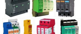
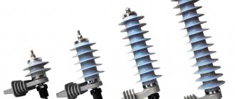
This is what devices for protection against lightning and switching overvoltages look like.
Replacing arresters with surge arresters
Basic electrical characteristics of surge suppressors 3-750 kV, recommended for replacing the corresponding valve arresters of groups I-IV according to GOST
The main electrical characteristics of surge suppressors 3-750 kV, recommended for replacing the corresponding valve arresters according to GOST, are summarized in Table 1. Similar characteristics of the mentioned valve arresters are not given here. The data in this table requires the following explanations:
1. The compared devices are designed for UHL climatic conditions.
2. The compared devices are designed for placement category “1” (in an open atmosphere). However, if necessary, they can be used in an open atmosphere, but under a canopy (category 2), and in enclosed spaces (category 3) according to GOST 15150 and GOST 15543.1.
3. The compared devices are designed to operate in an atmosphere of pollution degree II - IV according to GOST 9920.
4. The following abbreviations are used in Table 1:
Unom – rated voltage of the network in which the protective device is installed, kV rms.
Ump – the highest (maximum) long-term permissible operating voltage at the arrester or limiter, kV rms.
Upr.50 – breakdown voltage of the spark gaps of the arresters at a frequency of 50 Hz (on the left – no less, on the right – no more), kV rms.
Upr. and – pulse breakdown voltage of the spark gaps of the arresters at a pre-discharge time of 2-20 μs, kV max, no more.
Inom – rated discharge current, kA.
Urest. g.3, Urest. g.5, Urest. g.10, Urest. g.20, Urest. d.40 – remaining voltage at a pulse current with a front length of 8 μs (for arresters) and a shape of 8.20 μs (for surge arresters), kV max, no more, respectively, at currents of 3.5, 10, 20, 40 kA.
In. u. – amplitude of a rectangular current pulse with a duration of 2000 μs, A.
Urest. room 250, Urest. k.500, Urest. k.1000 and Urest. k.2000 remaining voltage at switching current 250, 500, 1000 and 2000 A with a length of 30.60 μs, kV max, no more
5. Valve arresters of all types (RVP, RVO, RVS, RVM, RVMG, RVMG, RVRD) 3-22 kV are designed to protect electrical equipment only from lightning overvoltages, 330 - 750 kV type RVMK - to protect it simultaneously from lightning and switching overvoltage.
6. The characteristics of group I arresters, except for 3.6 and 10 kV networks, are not given in Table 1, since for various reasons they were not mass-produced by our industry.
7. In Table 1, the characteristics of arresters of types RVMK - 330 and RVMK - 500 are borrowed from GOST, type RVMK - 750 - from TU 16.521.029-69.
8. The switching voltage of arresters of types RVMK - 330, RVMK - 500 and RVMK - 750 in the lightning overvoltage limiting mode is in the range of 720-820, and 2550 - 3000 kV, respectively.
9. The “equivalent” of arresters of type RVM-3 are two parallel-connected surge arresters - 3/550/3.6-10-III-UHL1, RVRD-3 - three parallel-connected surge arresters-3/550/3.6-10-III -UHL1, RVRD – two parallel-connected surge arresters-10/550/10.5-10-III-UHL1.
10. A separate table 3 shows the types of surge arresters for replacing RFs required when organizing neutral protection for 3-220 kV transformers.
Table 1
Basic electrical characteristics of RV and surge arrester 3-750 kV
| N0 | Protective apparatus | Unom, kV rms | Um. r., kV rms | Upr.50, KV max | Upr. and kV rms | Inom kA | Urest. g.3 kV max | Urest. g.5 kV max | Urest. g.10 kV max | Urest. g.20, Urest. g.40 kV max | In. u. A | Urest. g.250, kV max | Urest. g.500, kV max | Urest. g.1000, kV max | |
| 1 | 2 | 3 | 4 | 5 | 6 | 7 | 8 | 9 | 10 | 11 | 12 | 13 | 14 | 15 | |
| 1 | IV group (RVP), IV group (RVO) | 3 | 3,8 | 9-11 | 20 | 5 | 13 | 14 | — | — | — | — | — | — | |
| 2 | OPNp-3/550/3.6-10-III-UHL1 | 3 | 3,6 | — | — | 10 | — | 10,5 | 11,1 | 11,7 | 550 | 8,5 | 8,8 | 9,4 | |
| 3 | Group II (RVM) | 3 | 3,8 | 7,5-9 | 8 | 5 | 9 | 9,5 | 11 | — | — | — | — | — | |
| 4 | Group I (RVRD) | 3 | 3,8 | 7-8,5 | 7,5 | 5 | 8,6 | 9 | 10,5 | — | — | — | — | — | |
| 5 | IV group (RVP), | 6 | 7,5 | 16-19 | 32 | 5 | 25 | 27 | — | — | — | — | — | — | |
| IV group (RVO) | |||||||||||||||
| 6 | Group II (RVM) | 6 | 7,5 | 15-18 | 15,5 | 5 | 17 | 18 | 20 | — | — | — | — | — | |
| 7 | Group I (RVRD) | 6 | 7,5 | 14-17 | 15 | 5 | 16,5 | 17,8 | 19,5 | — | — | — | — | — | |
| 8 | OPNp-6/550/6.0-10-III-UHL1 | 6 | 6 | — | — | 10 | — | 17,8 | 19,2 | 21,6 | 550 | 14,3 | 14,9 | 15,8 | |
| 9 | OPNp-6/550/6.6-10-III-UHL1 | 6 | 6,6 | — | — | 10 | — | 19,5 | 21,1 | 23,8 | 550 | 15,7 | 16,4 | 17,4 | |
| 10 | OPNp-6/550/6.9-10-III-UHL1 | 6 | 6,9 | — | — | 10 | — | 20,3 | 22 | 24,8 | 550 | 16,4 | 17,1 | 18,2 | |
| 11 | OPNp-6/550/7.2-10-III-UHL1 | 6 | 7,2 | — | — | 10 | — | 22,8 | 23,9 | 25,7 | 550 | 19 | 19,7 | 20,3 | |
| 12 | Group IV (RVP, RVO) | 10 | 12,7 | 26-30,5 | 48 | 5 | 43 | 45 | — | — | — | — | — | — | |
| 13 | Group II (RVM) | 10 | 12,7 | 25-30 | 25,5 | 5 | 28 | 30 | 33 | — | — | — | — | — | |
| 14 | Group I (RVDV) | 10 | 12,7 | 24-29 | 25 | 5 | 27,5 | 20,5 | 32 | — | — | — | — | — | |
| 15 | OPNp-10/550/10.5-10-III-UHL1 | 10 | 10,5 | — | — | 10 | — | 31,1 | 33,6 | 37,8 | 550 | 25 | 26 | 21,7 | |
| 15a | OPNp-10/550/11.5-10-III-UHL1 | 10 | 11,5 | — | — | 10 | — | 33,7 | 36,4 | 41 | 550 | 27,2 | 28,3 | 30,1 | |
| 16 | OPNp-10/550/12-10-III-UHL1 | 10 | 12 | — | — | 10 | — | 35,5 | 38,4 | 43,2 | 550 | 28,6 | 29,8 | 31,7 | |
| 17 | OPNp-10/550/12.7-10-III-UHL1 | 10 | 12,7 | — | — | 10 | — | 37,8 | 40,6 | 45,7 | 550 | 30,2 | 31,5 | 33,5 | |
| 18 | Group III (RVS) | 15 | 18 | 38-48 | 67 | 5 | 57 | 61 | 67 | — | — | — | — | — | |
| 19 | Group II (RVM) | 15 | 19 | 35-43 | 57 | 5 | 47 | 51 | 57 | — | — | — | — | — | |
| 20 | OPNp-15/550/17.5-10-III-UHL1 | 15 | 17,5 | — | — | 10 | — | 50,9 | 53,9 | 57 | 550 | 41,2 | 43 | 45,5 | |
| 21 | Group III (RVS) | 20 | 24 | 49-60 | 80 | 5 | 75 | 80 | 88 | — | — | — | — | — | |
| 22 | Group II (RVM) | 20 | 24 | 47-56 | 74 | 5 | 62 | 70 | 74 | — | — | — | — | — | |
| 23 | OPNp-20/550/24-10-III-UHL1 | 20 | 24 | — | — | 10 | — | 69,8 | 73,9 | 78,2 | 550 | 56,6 | 59 | 62,4 | |
| 24 | Group III (RVS) | 35 | 40,5 | 78-97 | 125 | 5 | 122 | 130 | 143 | — | — | — | — | — | |
| 25 | Group II (RVM) | 35 | 40,5 | 75-90 | 116 | 5 | 97 | 105 | 116 | — | — | — | — | — | |
| 26 | |||||||||||||||
| 27 | |||||||||||||||
| 28 | OPNp-35/550/37-10-III-UHL1 | 35 | 37 | — | — | 10 | — | 110 | 118 | 133 | 550 | 88,1 | 91,8 | 97,7 | |
| 29 | OPNp-35/550/40.5-10-III-UHL1 | 35 | 40,5 | — | — | 10 | — | 128 | 135 | 145 | 550 | 107 | 111 | 114 | |
| 30 | Group III (RVS) | 110 | 102 | 200-250 | 285 | 5 | 315 | 335 | 367 | — | — | — | — | — | |
| 31 | Group II (RVMG) | 110 | 100 | 170-195 | 260 | 5 | 245 | 265 | 295 | — | — | — | — | — | |
| 32 | |||||||||||||||
| 33 | |||||||||||||||
| 34 | |||||||||||||||
| 34a | |||||||||||||||
| 36 | OPNp-110/550/73-10-III-UHL1 | 110 | 73 | — | — | 10 | — | 246 | 234 | 265 | 550 | 174 | 181 | 193 | |
| 36 | OPNp-110/550/77-10-III-UHL1 | 110 | 77 | — | — | 10 | — | 228 | 246 | 277 | 550 | 183 | 194 | 203 | |
| 37 | OPNp-110/550/88-10-III-UHL1 | 110 | 88 | — | — | 10 | — | 260 | 282 | 317 | 550 | 209 | 218 | 232 | |
| 37a | OPNp-110/550/100-10-III-UHL1 | 110 | 100 | — | — | 10 | — | 317 | 332 | 357 | 550 | 264 | 274 | 282 | |
| 38 | OPNp-110/800/73-10-III-UHL1 | 110 | 73 | — | — | 10 | — | 224 | 241 | 264 | 500 | 189 | 198 | 210 | |
| 39 | OPNp-110/800/88-10-III-UHL1 | 110 | 88 | — | — | 10 | — | 264 | 284 | 312 | 800 | 223 | 234 | 249 | |
| 39a | OPNp-110/800/100-10-III-UHL1 | 110 | 100 | — | — | 10 | — | 296 | 316 | 347 | 800 | 248 | 260 | 276 | |
| 40 | Group III (RVS) | 150 | 138 | 275-345 | -375 | 5 | 435 | 465 | 510 | — | — | — | — | — | |
| 41 | Group II (RVMG) | 150 | 138 | 230-265 | 370 | 5 | 340 | 370 | 410 | — | — | — | — | — | |
| 42 | |||||||||||||||
| 43 | |||||||||||||||
| 44 | |||||||||||||||
| 45 | OPNp-150/550/100-10-III-UHL1 | 150 | 100 | — | — | 10 | — | 317 | 332 | 357 | 550 | 264 | 274 | 282 | |
| 46 | OPNp-150/550/110-10-III-UHL1 | 150 | 110 | — | — | 10 | — | 349 | 366 | 398 | 550 | 291 | 301 | 311 | |
| 47 | OPNp-150/550/120-10-III-UHL1 | 150 | 120 | — | — | 10 | — | 380 | 399 | 428 | 550 | 317 | 328 | 339 | |
| 48 | OPNp-150/800/100-10-III-UHL1 | 150 | 100 | — | — | 10 | — | 296 | 316 | 347 | 800 | 248 | 260 | 276 | |
| 49 | OPNp-150/800/110-10-III-UHL1 | 150 | 110 | — | — | 10 | — | 326,8 | 352 | 386 | 800 | 276 | 289 | 307 | |
| 50 | OPNp-150/800/120-10-III-UHL1 | 150 | 120 | — | — | 10 | — | 355 | 383 | 420 | 800 | 300 | 315 | 334 | |
| 51 | III group (PBC) | 220 | 198 | 400-500 | 530 | 5 | 630 | 670 | 734 | — | — | — | — | — | |
| 52 | Group II (RVMG) | 220 | 198 | 340-390 | 515 | 5 | 475 | 525 | 570 | — | — | — | — | — | |
| 53 | OPNp-220/550/176-10-III-UHL1 | 220 | 176 | — | — | 10 | — | 512 | 554 | 623 | 550 | 412 | 430 | 457 | |
| 54 | |||||||||||||||
| 55 | |||||||||||||||
| 56 | OPNp-220/800/146-10-III-UHL1 | 220 | 146 | — | — | 10 | — | 434 | 467 | 513 | 800 | 367 | 384 | 408 | |
| 57 | OPNp-220/800/152-10-III-UHL1 | 220 | 152 | — | — | 10 | — | 452 | 486 | 534 | 800 | 382 | |||
· Table 2
· Table for determining the replacement of valve arresters with surge arresters 3-750 kV.
| Arrester | Surge suppressor |
| RVP-3 (IV group) | OPNp-3/550/3.6-10-III-UHL1(2) |
| RVO-3 (IV group) | OPNp-3/550/3.6-10-III-UHL1(2) |
| RVM-3 (II group) | 2x OPNp-3/550/3.6-10-III-UHL1(2) |
| RVRD-3 (I group) | 3x OPNp-3/550/3.6-10-III-UHL1(2) |
| RVP-6 (IV group) | OPNp-6/550/7.2-10-III-UHL1(2) |
| RVO-6 (IV group) | OPNp-6/550/7.2-10-III-UHL1(2) |
| VM-6 (II group) | OPNp-6/550/6.0-10-III-UHL1(2) |
| RVRD-6 (I group) | 2x OPNp-6/550/6.0-10-III-UHL1(2) |
| RVP-10 (IV group) | OPNp-10/550/12.7-10-III-UHL1(2) |
| RVO-10 (IV group) | OPNp-10/550/12-10-III-UHL1(2) |
| RVM-10 (II group) | OPNp-10/550/10.5-10-III-UHL1(2) |
| RVRD-10 (I group) | 2x OPNp-10/550/10.5-10-III-UHL1(2) |
| RVS-15 (III group) | OPNp-15/550/17.5-10-III-UHL1 |
| RVM-15 (II group) | OPNp-15/550/17.5-10-III-UHL1 |
| RVS-20 (III group) | OPNp-20/550/24-10-III-UHL1 |
| RVM-20 (II group) | OPNp-20/550/24-10-III-UHL1 |
| RVS-35 (III group) | OPNp-35/550/40.5-10-III-UHL1 |
| RVM-35 (II group) | OPNp-35/550/37-10-III-UHL1 |
| RVS-110 (III group) | OPNp-110/550/88-10-III-UHL1 |
| OPNp-110/550/100-10-III-UHL1 | |
| OPNp-110/800/88-10-III-UHL1 | |
| OPNp-110/800/100-10-III-UHL1 | |
| RVMG-110 (II group) | OPNp-110/550/88-10-III-UHL1 |
| OPNp-110/800/88-10-III-UHL1 | |
| RVS-150 (II group) | OPNp-150/420/120-10-III-UHL1 |
| OPNp-150/550/120-10-III-UHL1 | |
| OPNp-150/800/120-10-III-UHL1 | |
| RVMG-150 (II group) | OPNp-150/550/110-10-III-UHL1 |
| OPNp-150/800/110-10-III-UHL1 | |
| RVS-220 (III group) | OPNp-220/800/176-10-III-UHL1 |
| RVMG-220 (II group) | OPNp-220/800/152-10-III-UHL1 |
| RVMG-330 (II group) | OPNp-330/800/210-10-III-UHL1 |
| OPNp-330/800/220-10-III-UHL1 | |
| OPNp-330/800/230-10-III-UHL1 | |
| OPNp-330/1200/210-10-II-UHL1 | |
| OPNp-330/1200/220-10-II-UHL1 | |
| OPNp-330/1200/230-10-II-UHL1 | |
| RVMK-330P | OPNp-330/800/210-10-III-UHL1 |
| OPNp-330/800/220-10-III-UHL1 | |
| OPNp-330/800/230-10-III-UHL1 | |
| OPNp-330/1200/210-10-II-UHL1 | |
| OPNp-330/1200/220-10-II-UHL1 | |
| OPNp-330/1200/230-10-II-UHL1 | |
| RVMG-500 (II group) | OPNp-500/1200/303-20-II-UHL1 |
| OPNp-500/1200/318-20-II-UHL1 | |
| OPNp-500/1200/333-20-II-UHL1 | |
| OPNp-500/1500/303-20-II-UHL1 | |
| OPNp-500/1500/318-20-II-UHL1 | |
| OPNp-500/1500/333-20-II-UHL1 | |
| OPNp-500/2100/303-20-II-UHL1 | |
| OPNp-500/2100/318-20-II-UHL1 | |
| OPNp-500/2100/333-20-II-UHL1 | |
| RVMK-500P | OPNp-500/1200/303-20-II-UHL1 |
| OPNp-500/1200/318-20-II-UHL1 | |
| OPNp-500/1200/333-20-II-UHL1 | |
| OPNp-500/1500/303-20-II-UHL1 | |
| OPNp-500/1500/318-20-II-UHL1 | |
| OPNp-500/1500/333-20-II-UHL1 | |
| OPNp-500/2100/303-20-II-UHL1 | |
| OPNp-500/2100/318-20-II-UHL1 | |
| OPNp-500/2100/333-20-II-UHL1 | |
| RVMK-750P | OPNp-750/2100/455-20-II-UHL1 |
| OPNp-750/2100/465-20-II-UHL1 | |
| OPNp-750/2100/475-20-II-UHL1 | |
| RVM-750 | OPNp-750/2100/455-20-II-UHL1 |
| OPNp-750/2100/465-20-II-UHL1 | |
| OPNp-750/2100/475-20-II-UHL1 |
table 3
Table for determining the replacement of valve arresters with surge arresters required when organizing neutral protection for 3-220 kV power transformers.
| Unom, kV | Valve arrester | Surge suppressors |
| 3 | RVM-3 | OPNp-3/550/3.6-10-III-UHL1 |
| 6 | RVM-6 | OPNp-6/550/6.0-10-III-UHL1 |
| 10 | RVM-10 | OPNp-10/550/10.5-10-III-UHL1 |
| 15 | RVM-15 | OPNp-15/550/17.5-10-III-UHL1 |
| 20 | RVM-20 | OPNp-20/550/24-10-III-UHL1 |
| 35 | RVM-35 | OPNp-35/550/37-10-III-UHL1 |
| 110 | 2x RVS-20; RVS-35 + RVS-15, RVS-60 | OPNp-110/550/56-10-III-UHL1 |
| 150 | RVS-110 | OPNp-150/550/100-10-III-UHL1 |
| 220 | RVS-150 | OPNp-220/550/120-10-III-UHL1 |
Main portals (built by editors)
Arresters
The operating principle of arresters is based on the ability of high voltage to pierce an air gap. The breakdown voltage of the gap depends mainly on the size of the air gap.
Air gap
The design of the air discharger is very simple. The size of the air gap between the phase and ground wires is selected in such a way that it is guaranteed not to break through at the operating voltage, but if this value increases multiple times, a breakdown occurs. In this case, an electrical circuit is formed through an arc discharge between the phase and the protective ground. The current pulse flowing into the grounding device relieves overvoltage and protects power circuits from damage.
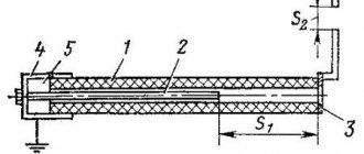
Valve arrester
An improved model of an air arrester is a valve-type arrester. The valve arrester design includes several components:
- spark gap divided into several air gaps;
- resistor.
The working resistor is a set of disks connected in series, made of vilit or tirite. The properties of these materials are such that the current-voltage characteristic of the operating resistance is nonlinear. This property allows large surge currents to pass through with a small voltage drop across the element itself. Due to the nonlinearity of the characteristic, the arrester is called valve-type. The operation of valve-type arresters occurs almost silently; in addition, such abundant release of gas and flame is not observed as in the case of an air discharger.
▍Act two. Mini lightning.
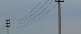
Not all high-mounted conductors can be grounded to successfully redirect the discharge energy to the ground.
For example, an antenna - it must be high and cannot be grounded, otherwise it will stop receiving signals. Is it possible to make a device that would, for example, connect the antenna to the ground only at the moment of a lightning strike, and at the same time have no effect the rest of the time? You can, and this device is called a spark gap. Here is an example of a spark gap for electrical equipment from the late 19th century:
The idea of protection is simple - a minimum permissible gap is created between the protected conductor and the ground in the arrester so that during normal operation the voltage does not exceed the breakdown voltage of the gap. If for some reason the voltage in the protected line increases (due to a lightning strike or due to surges from the operation of electrical equipment), then an electrical breakdown occurs in the gap - an electric arc is ignited, which, due to the ionization of the gas, conducts current well. It is this arc that provides a temporary electrical connection to the ground, and goes out if the voltage drops below the arc quenching voltage.
But there are two problems. The first is the hardly predictable breakdown voltage of the spark gap - a change in temperature, air humidity - and the voltage changes. A little corrosion - the voltage has changed. The crooked adjuster handles have changed a lot. The second drawback is more fundamental - the voltage at which breakdown occurs and the voltage at which the arc goes out are different. Moreover, the arc ignition voltage also depends on the rate of voltage rise. The graph in the picture just shows the “hump” - until the spark gap is triggered, the voltage has time to increase, then the arc lights and the voltage drops. The dotted line shows the voltage graph when protected by a varistor.
The picture is taken from here.
If the first drawback was overcome by enclosing the spark gap in a sealed flask filled with a pre-prepared mixture of gases, then nothing could be done about the second. Yes, with various tricks you can reduce the difference between the breakdown voltage and the voltage when the arc goes out, but not radically. Moreover, the quenching voltage must be HIGHER than the voltage of the power source (*with reservations). Otherwise, an unpleasant situation may arise when a lightning strike breaks through the arrester and goes into the ground, but the generator powering the line will not allow the arc to go out. And the arc in the spark gap will burn until one of them breaks. Here is an example of an RB-5 arrester, domestically produced from communication equipment - the flask is sealed and filled with an inert gas:
In principle, before the widespread use of semiconductor devices (somewhere before the mid-60s), protection in the form of arresters suited everyone. With a proper insulation safety margin, most equipment could withstand a short-term voltage surge of a couple of kV (until the arrester operates). But then semiconductor devices came into widespread use, for which even a small short-term increase in voltage meant death.
Dischargers are still used today and very widely. Moreover, arresters are produced in a huge range for all occasions, from small ones for protecting communication lines to huge ones for protecting power lines. Here's an example of what the arresters look like in a mini-PBX board (cylindrical with the manufacturer's brand EPCOS), to protect against high voltage pulses that may end up in the telephone line:
Surge arresters - surge suppressors
Surge suppressors are the next step in the evolution of devices that protect against surge voltage surges. This device does not contain air gaps. The main element of the device is a varistor. To be more precise, a set of varistors. To obtain the required performance characteristics, varistors are connected to each other in serial or parallel - serial blocks.
The basis of the varistor is zinc oxide. During the manufacturing process of a varistor, oxides of other metals are also added. StabExpert.ru reminds that as a result, the finished product is a set of p–n junctions connected in parallel and in series. The presence of these semiconductor junctions determines the nonlinear properties of the varistor. The varistors are enclosed in a porcelain or polymer surge suppressor housing. The resistance of arrester varistors is very high in the operating voltage range. When a surge voltage occurs, the resistance of the surge arrester drops sharply, allowing the surge current to flow to ground.
Surge suppressors have some design and functional differences. Classification of surge arresters is carried out according to the following criteria:
- insulation material;
- device designs;
- operating voltage;
- installation location.
Regarding insulation, it has already been said that porcelain or a polymer composition is used. Structurally, surge suppressors can be single-column or multi-column. Surge arresters are produced for each voltage class: 6-10 kilovolts and above. Surge suppressors are installed in closed or open switchgears (closed switchgear, outdoor switchgear).
Specifications
A specific model has the following technical characteristics:
- response time - depending on the speed of reaction to a voltage drop;
- operating voltage - the value of a given value at which the element is able to function without destruction for a certain time period;
- rated overvoltage - the value that the product can withstand for 10 seconds;
- leakage current - depends on the effect of voltage on the arrester and depends on the ohmic resistance of the element. The value of this characteristic is in hundredths or thousandths of amperes flowing through the protective coating and semiconductor element;
- discharge current – value during a pulsed voltage surge;
- resistance to overvoltage wave current - the ability not to be damaged when exposed to increased voltage.
The surge arresters are standardized according to the values of the specified characteristics.
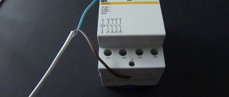
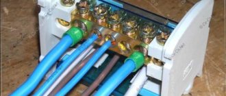
Home modular surge protectors for installation in 0.4 kV switchgears
To protect in-house electrical wiring and household appliances from surges of lightning and transient nature, many electrical manufacturers produce compact modular devices that are conveniently located in distribution cabinets.
Such surge protectors are installed on a DIN rail.
Installation
Modular SPDs are connected between the phase and protective ground wires. The connection must be made after the circuit breaker. In this case, when an overvoltage occurs and the device’s varistor opens, the increased varistor current flows through the switch, causing the protection to operate. By turning off, the circuit breaker breaks the connection between the load and the external network, which is a source of increased voltage.