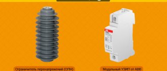
What is an SPD and what does it protect against?
An SPD is a device that protects equipment and electrical devices in a 220-380V network from surge voltages.
At the same time, do not confuse pulse overvoltage simply with increased voltage, which occurs in emergency situations - a break in the neutral line or a phase contact with the neutral conductor.
The pulse lasts no more than 1 millisecond.
No voltage relay has time to work during this time.
In addition to the abbreviation SPD, you can also find other common names. For example, OPS - network overvoltage limiter or SVP - surge voltage limiter.
Despite the different names, the functional purpose of all these devices is the same. They must perform two main tasks:
- protect equipment from the effects of lightning strikes
And not necessarily from a direct hit, but also from the resulting “noise” and pulse discharges during a thunderstorm.
Not only working devices, but also “sleeping” ones can fail from them.
That is, those that are simply plugged into an outlet - TV, refrigerators, chargers.
- protect against overvoltage during switching
It turns out that for pulse anomalies to appear in the network, it is not at all necessary that lightning strike a power line near your home. It is enough for someone in the same network (0.38-6-10 kV) to turn on the capacitor banks, start a powerful electric motor or welding machine.
As you understand, talking about the relevance of installing surge protectors in this case is necessary not only for private houses, but also for apartments in high-rise buildings. This switching will be accompanied by a short-term impulse that will burn the electronic components of your TV, washing machine or computer.
Neither RCDs, nor differential automatic devices, nor voltage relays will help with all this.
But an SPD can really save expensive devices. Sometimes such impulses do not lead to a major breakdown, but are accompanied by a system freeze, memory loss, etc. And this again means additional costs for repairs, adjustments and maintenance.
If you take all household electrical appliances and divide them into categories of electrical resistance to voltage surges, you will get the following plate:
Surge protection: private house with single-phase power supply
Installation of electrical wiring in a private house, especially one made of wood and flammable materials, requires careful adherence to electrical safety rules.
It is necessary to take into account that the building can be powered using different grounding schemes:
- typical old TN-C;
- or modern, safer TN-S or its modifications.
Let's look at both cases.
SPD connection diagram: 2 options according to the TN-S grounding system
The picture below shows a detailed circuit with protection of combined class 1+2, which is used for installation after the input circuit breaker.
The surge suppressor varistor is built into the module housing and protects the electrical circuit from direct or remote atmospheric lightning discharges.
The signal flag, traditional for all SPDs, has two colors:
- the green position indicates that the device is working properly and is ready for operation;
- red - about the need for replacement in case of operation or burnout.
Such a module can be used in all grounding systems, not just TN-S. It has 3 connection terminals:
- top left L - phase wire;
- top right PE - protective grounding conductor;
- bottom N - neutral wire.
The SPD protects the electric meter and all circuits after it.
The next diagram shows an option for using protection with an RCD. After it, an additional working zero bus N1 is created, from which all consumers in the apartment are powered.
The scheme seems clear, there should be no questions.
For additional TN-CS and TT grounding systems, I propose two more schemes for study and analysis. They also have an SPD mounted in the input device.
I do not show the meter connection circuits, voltage control relays RKN and RCD, as well as consumers in detail. But the principle is clear: a PE protective bus is used.
But the old grounding system does not have it, which reduces reliability and safety. But it still provides protection, which is why it is considered.
SPD connection diagram using TN-C grounding system
The absence of a PE bus dictates the need to connect an SPD only between the potentials of the phase wire and PEN. There are simply no other options.
The method of installing protection for single-phase wiring is shown on the left, and three-phase wiring is shown on the right.
The overvoltage pulse is removed by the principle of creating an artificial short circuit in the supply circuit.
Device and principle of operation
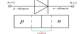
Structurally, the surge suppressor includes a semiconductor element with a nonlinear resistance value. As a rule, the role of such elements is played by vilitic disks made on the basis of zinc oxides with the inclusion of certain impurities in the composition. On the outside, the disks are covered with a protective jacket, and at the ends they have electrical terminals, one of which is connected to the protected electrical network, and the second is grounded. An example of a private version of a surge suppressor device is presented in Figure 1 below:
surge suppressor device
The operation of an arrester is similar to a conventional varistor; the distinctive feature of the limiter is some differences with the characteristics of a varistor in terms of conductivity and slew rate. The principle of operation of the surge suppressor lies in its nonlinear current-voltage characteristic (volt-ampere characteristic). This means that at the rated voltage the resistance of the varistors is quite large and no current flows through them - its insulation resistance is comparable to the insulation of cables, insulators and electrical appliances.
In operating mode, when lightning discharges or other high-voltage pulses occur, the resistance of nonlinear resistors inside the limiter decreases sharply. As a rule, this value approaches zero or is disproportionately less than the resistance of the network and all devices connected to it. Therefore, during switching or lightning overvoltages, the discharge current flows only through the surge suppressor to the ground, which ensures the protection of electrical equipment.
The limits of response of a surge suppressor to lightning strikes or other pulse overvoltages are determined by its current-voltage characteristics.
current-voltage characteristic of surge arrester
As you can see from Figure 2, when the surge suppressor operates up to 600V, the current flowing through it will be zero. As soon as this value crosses the 600V mark, the resistance will sharply decrease and the flowing current will increase to hundreds and thousands of amperes.
Here the characteristic curve is represented by three sections:
- 1 – region of zero or ultra-low currents;
- 2 – area of average current loads;
- 3 – area of maximum current.
Surge suppressors - how to connect the device
There are connection diagrams for both one phase and three phases. In addition to the OIN-1 device described here, there are many identical protective voltage limiters from different brands, so the principle of their connection is no different from each other. The typical circuit presented below can practically be used with any type of device.
In the first option, the device is connected to the circuit according to a parallel connection scheme, the second option shows a connection in series with a disconnector. It follows from this that when the surge suppressor operates with a sharp increase in the mains voltage, the disconnector will open the supply circuit.
Attention! In addition to the correct installation of the phase and grounding cables, the cross-section and length of the installation wire are of significant importance.
From the connection point on the terminal block of the device to the grounding bus, the length of the installation wire should not be more than 500 mm.
Application
A surge suppressor is used to prevent the build-up of overvoltage on electrical equipment with the subsequent transfer of the discharge pulse to ground.
example of using an arrester
Nonlinear limiters are widely used in power lines, where they act as lightning protection, and the wires themselves are lightning rods. For industrial purposes, surge suppressors are used to protect various electrical devices and personnel, for example, at traction and transformer substations, switchgears, etc. In household devices, surge arresters are used for installation in electrical panels at the entrance to the building or to protect any valuable equipment.
Selection of arrester
When choosing an arrester for a particular case, it is necessary to apply the official recommendations of international standards or guidelines (IEC 60099-5). The limiter parameters are selected based on the purpose, installation location, required level of overvoltage limitation, network diagram and its parameters (neutral grounding method, maximum operating voltage of the network, degree of compensation of capacitive current to the ground and its magnitude, etc.).
For their intended purpose, limiters are used to protect equipment from lightning and switching overvoltages. The installation locations, as well as the distances from the protected equipment to the limiters, must comply with the requirements of the “Rules for Electrical Installations”, section 4, seventh edition of the PUE.
Kinds
Due to the wide variety of functions performed, EDs are classified according to the following indicators:
Structure of the symbol of the surge arrester
- The voltage class for which the element is designed. This characteristic is determined by the parameters of the network on which the device is used,
- Protective coating material - the most widely used elements are those using porcelain and polymers,
- Security class - depending on whether the protective unit is used indoors or in an open electrical installation,
Climatic version: U, HL, UHL and others - The number of elements and phases - taking into account the parameters of the equipment or line.
A combination of several devices can be used to provide stepwise protection.
It will be interesting➡ What is the selectivity of circuit breakers + principles for calculating selectivity
Designation of surge arresters and arresters on the diagram
Material
Depending on the material used for the protective jacket, protection can be achieved using the following types of devices:
- Porcelain is the most common variety. Ceramics are resistant to ultraviolet radiation, so they can be freely used in open installations. Due to their high mechanical strength, such elements can simultaneously serve as a supporting structure. The disadvantages include large weight and fragility, which threatens personnel injury when fragments fly away as a result of the destruction of the element.
- Polymer - rubber, vinyl and other artificial compounds are used as the outer covering material. These devices are resistant to moisture, have lighter weight and good dielectric properties, can withstand significant mechanical stress, but accumulate atmospheric moisture on the surface and react poorly to sunlight.
- Single-column - in the form of a semiconductor element with nonlinear voltage characteristics, with the number of disks, depending on the category of equipment.
- Multi-column - used on high-voltage equipment and consist of several components combined into a single unit. They are distinguished by increased reliability and ability to respond to various load characteristics.
The choice of surge arrester type depends on the parameters of the equipment and its operating conditions.
Laboratory work No. 3
Surge arresters and arresters.
To reduce the level of overvoltages occurring in the contact network and ensure reliable operation of the protection, special arresters are installed on the contact network; when they break down, the contact network is briefly connected to the rails and the discharge current goes into the ground. The arresters are installed on the supports of the contact network, except for anchor and other supports that have guys, since when the arrester is triggered, the guys can be damaged, which can lead to the fall of the support.
On the contact network, horn gaps are used with two sequential spark gaps of 5+1 mm at direct current and 45+5 mm at alternating current (Fig. 9.14, a, b). A double spark gap is created in order to eliminate false triggering when one of them is accidentally shorted (for example, by a bird).
Horn arresters are placed on brackets or on the tops of supports and, to improve inspection from the train, perpendicular or at an angle of 45° to the track axis. It is not allowed to place any wires above the horn arrester at a distance of up to 2 m. One of the outer horns is connected to the contact network with a conductor with a cross-section of at least 25 mm2 for copper. The second extreme horn is attached to the traction rail. To make horns, a steel rod with a diameter of 12 mm is used.
Horn arresters are placed on direct current lines, usually on transitional supports of anchor sections, so that the distance from it to the anchoring of the supporting cable and contact wire is no more than two spans between the supports, and to the sectional disconnector - no further than one span.
Rice. 9.14. Horn arrester for areas of direct (a) and alternating (b) current; 1 — support insulator wire holder; 2 — wire to catenary; 3 - wire to the common ground line; 4 - insulators; 5 - arc-extinguishing horns.
Recently, overvoltage limiters have become widespread, which are connected to the contact network through a horn arrester with a single air gap of 10 + 2 mm for direct current and 80 + 5 mm for alternating current, shunted by a fuse insert made of a single copper wire with a diameter of 1.4 mm or from two copper wires with a diameter of 0.68 mm each (Fig. 9.15, a).
The arrester and the horn arrester must be mounted on the same frame, and the base of the arrester, on which the clamp for connecting the grounding conductors is located, must be insulated from the frame with an insulation resistance of at least 10 kOhm.
The surge arresters are connected to electrical cross-connectors with M-70 or PBSM-70 wires, and on supply lines and overhead lines 10 (6), 35 kV and DPR 25 kV directly to the line wires with wires (loops) with a cross-section of at least 25 mm2 for copper (Fig. 9.15, b).
On overhead lines 6-35 kV and DPR 25 kV, valve and tubular arresters RT-35 are used, supplemented with an external spark gap.
Rice. 9.15. DC surge suppressor (a); installation of surge arresters on a support (b): 1 - bracket; 2 — arrester beam; 3 — support bar; 4, 5 — arched horns; 6 - surge arrester; 7 - insulator; 8, 9, 10 — connecting, string, grounding clamps; 11 — hook bolt;
12 - wire 01.4 mm; 13 - wire M-70 or PBSM-70
The tubular arrester consists of a bakelite tube with an internal diameter of 10 mm and two metal tips. Inside the bakelite tube there is a fiber tube with a rod electrode. Between this electrode and one of the metal tips of the bakelite tube there is a gap 175 mm long, which forms the internal spark gap. The switchable current limits of the tubular arrester are 0.8–5 kA.
When there is an overvoltage on a 6-35 kV overhead line, a 25 kV DPR, the internal spark gap is closed. Under the influence of the high temperature of the formed arc, the fiber releases a large amount of gases, which, when exhausted, provide extinguishing of the arc. The external spark gap is made of a steel rod with a diameter of 10 mm and serves to protect the organic insulation of the spark gap from destruction.
Tubular arresters are attached to grounded structures in such a way that structural elements and rolling stock do not interfere with the free exhaust of gases when the arresters are triggered. To prevent the possibility of moisture accumulation in the internal cavity of the arrester, its open end is installed at an angle of at least 15°, and in places of increased contamination - up to 45° to the horizontal.
The electrode of the external spark gap, secured by a rod insulator, is connected to the overhead line wire with a copper wire with a cross-sectional area of at least 25 mm2.
The grounding wire of the surge suppressor, as well as the horn and tubular arrester, is connected to the traction rail, and away from the tracks - to an individual grounding circuit with a resistance of no more than 3 ohms at direct current and 10 ohms at alternating current.
During new construction, renovation, reconstruction and major repairs of the contact network of electrified sections of high-speed, heavy-duty, as well as categories I and II railways, surge arresters are used instead of arresters. The installation locations of surge arresters and surge arresters, as well as the technical characteristics of surge arresters, are given in Appendix 10.
Overvoltage protection of contact networks
Arresters and arresters are installed in the following places.
On a DC contact network:
• at the anchorage of catenary wires (Fig. P10.1, a);
• on non-insulating and normally closed insulating (Fig. P10.1, b) mates - on one branch of the mate, and on insulating normally open (Fig. P10.1, c) mates - on both anchored branches;
• for artificial structures on catenary anchorages on both sides of the structure when its length is 80 m or more (Fig. P10.1, d) and on one side of the structure - when its length is less than 80 m (Fig. P10.1, e);
• at the points where the supply lines are connected to the catenary or SG (Fig. P10.1, f);
• on supply lines at a distance no further than 100 m from the beginning of the air route at the traction substation and then at least every 1-1.5 km (Fig. P10.1, g, h).
On the AC contact network:
• on both sides at insulating joints and neutral inserts (Fig. P10.2, a);
• at the connection points along each path of autotransformer points 2×25 kV (Fig. P10.2, b);
• for suction transformers, at both terminals of their primary winding connected to the contact network (Fig. P10.2, c);
• at the end of the cantilever section of the contact network, consisting of 2 or more anchor sections (Fig. P10.2, d);
• at the points of connection of supply lines (with a length of up to 300 m) to the contact network and along the length of the supply lines (Fig. P10.2, e, f).
At docking stations (Fig. P10.3):
• on DC supply lines - the same as on the contact network;
• on AC supply lines - at the first and last branches of them to the grouping points and at a distance no further than 200 m from the traction substation with a line length of more than 300 m. If there are overvoltage limiters on the feeders of the traction substation, surge protectors-25 kV, the arresters on the supply lines are not are installed;
in places subject to frequent lightning strikes.
surge arrester
Purpose
Surge surge protectors are designed to protect electrical appliances and equipment from the effects of high-voltage voltage pulses. Due to their simplicity of design and reliability, they are widely used in the field of power supply. These protection devices have replaced outdated, very bulky valve arresters. Unlike its predecessors, the operating principle of the limiter is not based on the use of spark gaps. As the main working element in the arrester, nonlinear resistors are used, made of a material based on zinc oxide.
Device
The primary and main element that makes up the surge suppressor is a varistor, which acts as a nonlinear variable resistor. Structurally, surge arresters consist of varistors housed in a housing made of porcelain or high-strength polymer. The design of the limiter is made taking into account conditions that ensure explosion safety in the event of short circuit currents. Depending on the purpose and installation location, surge arresters can be designed in various versions. For limiters used to protect power lines and equipment of industrial facilities, a contact bolt is provided on the housing cover for connection to the network; the arrester kit includes a base plate insulated from contact with the ground.
The devices, designed to protect against peak voltage surges in the electrical equipment of an apartment or country house, are very compact, have an attractive design, and are also equipped with a device for mounting on a DIN rail. Depending on the category of complexity, they can be equipped with an indication of operating modes and remote control.
Principle of operation
The principle of operation of surge arresters is explained by the nonlinear nature of the current-voltage characteristics (VC) of varistors. For their manufacture, a material is used where zinc oxide is used in a mixture with oxides of other metals. Due to the composition of this mixture, a column assembled from varistors is a combination of parallel and series connections of pn junctions, which determines the nature of the current-voltage characteristics of nonlinear limiter resistors.
When the voltage characteristics in the network correspond to the nominal values, the limiter is in a non-conducting state. The current in varistors is negligible and is explained by their capacitive nature. When a voltage pulse appears in the network, the magnitude of which can cause a breakdown of the insulation of electrical equipment, a significant current pulse will occur in the circuit of nonlinear resistors of the arrester, in accordance with their current-voltage characteristics. Ultimately, this reduces the magnitude of the overvoltage to parameters that are safe for trouble-free operation of the equipment. When the network voltage returns to normal, the surge arrester returns to non-conducting mode.
Types of surge arresters
The designs of surge arresters offered by manufacturers to power engineers are very diverse; they are distinguished by the following characteristics:
1. Type of insulation (porcelain or polymer).
2. Design (one or more columns).
3. The magnitude of the operating voltage.
4. Place of installation of the limiter.
If we talk about surge suppressors installed on a DIN rail, then the devices are initially divided into single-phase and three-phase. In addition, modular surge arresters (also known as SPDs) are divided into three main classes: B, C and D. Class B limiters are installed at the entrance to the building, C - directly in the distribution board of an apartment or house, D - on separate equipment that needs to be protected from interference, if class B and C surge arresters cannot cope with this.
Classes or types of SPDs - how do they differ?
All SPDs are divided into three classes or three types. These classes suggest in which places this or that device should be installed.
Class 1 Protects against overvoltage caused by a direct lightning strike on a building or lightning rod.
This type is designed for peak current with a rise time of 10/350ms.
What does this mean? This means that the current rises to its maximum value within 10ms. Then its value drops by 50% after 350ms.
This is observed precisely with a direct lightning strike. This is a very short exposure time, to which other protective devices often do not have time to react. And with sufficient pulse current, they simply fail, without protecting the connected equipment in any way.
But an SPD with maximum values of this parameter is guaranteed to protect the circuit at least once.
SPDs of class 1 are installed directly on the input switchboards of industrial and administrative buildings.
Type 1 is used if there is a lightning protection system - a lightning rod, a metal mesh on the building.
By the way, devices of class 1 of the appropriate design, with air input via SIP wire and the presence of a good grounding loop, can be easily installed directly on the support through special piercing clamps and fittings.
Class 2 Provides protection against pulsed voltage surges that appear when turning on/off very powerful equipment, or during an indirect lightning strike.
They are designed for peak current with a rise time of 8/20ms. That is, the maximum current is reached in 8 ms, and it drops by half in 20 ms.
Automatic machines, RCDs, relays again miss such an impulse, not having time to react in time.
SPDs of class 2 should be installed in the input switchgear of multi-apartment residential buildings or in street ASUs of private cottages and houses.
When entering the building by air, this condition is directly regulated by the rules of the PUE.
It turns out that SPD T-2 should be used almost always.
Class 3 Protects against residual pulse overvoltages formed during short circuits, or after extinguishing the main impulse, by the first two classes of SPDs.
The third class is often built into surge protectors and extension cords.
Very sensitive electronic equipment needs this protection. For example, expensive medical devices, computers, etc.
The third class is used only as additional protection to T-2, and it has a lower discharge capacity.
Type T-3 must be installed if the devices are located more than 30 meters from the input SPD T-2.
Please note that to ensure selectivity of protection, SPDs of different classes cannot be installed in parallel one after the other in the same place. Otherwise, the maximum lightning current will initially go through the wrong device and simply burn it out.
To prevent this from happening, there must be a decoupling element between SPDs of different classes - inductance. The role of this inductance is performed by an ordinary cable or wire.
The recommended distance between different SPDs is at least 10 meters.
SPD: features of selection and application
Even short-term impulse voltage surges, several times higher than the nominal voltage, can cause irreparable damage to expensive electrical equipment and electronics, or even cause a fire. Overvoltage in networks can occur due to thunderstorms, accidents or transients. For example, pulse overvoltages can result from lightning hitting a lightning protection system or power line, switching powerful inductive consumers such as electric motors and transformers, or short circuits.
A standard B or C (possibly B+C) arrester consists of two components:
- Limiter base
- Replaceable insert with protective element
The basis
The base of the protective device is mounted on a TS35 DIN rail. It has two clamps. Connect the phase (L) or neutral (N) wire, which may have too much electrical potential. On the other side, connect the PE protective conductor, which is connected to the protective line of the switchgear.
The protective conductor should have a minimum cross-section of 4 mm2, but it wouldn't hurt to go larger. After all, there is a possibility that a very high current will flow.
There are 3 contacts under the PE terminal. As standard, the kit includes a plug that is inserted into the right place and allows you to connect the wires. Thanks to these clips, it is possible to remotely notify in case of damage to the insert or its burnout. This signal can be connected, for example, to the input of the alarm control unit (see diagram). In this case, the control panel will be informed that the insert is damaged by opening the electrical circuit between the red and green wires.
Insert
The insert contains all the most important elements thanks to which the defender functions correctly:
- Class B (Type I) - the main element is simply the spark gap.
- Class C (type II) - here the varistor part is the main element.
Specifications
A specific model has the following technical characteristics:
- response time - depending on the speed of reaction to a voltage drop;
- operating voltage - the value of a given value at which the element is able to function without destruction for a certain time period;
- rated overvoltage - the value that the product can withstand for 10 seconds;
- leakage current - depends on the effect of voltage on the arrester and depends on the ohmic resistance of the element. The value of this characteristic is in hundredths or thousandths of amperes flowing through the protective coating and semiconductor element;
- discharge current – value during a pulsed voltage surge;
- resistance to overvoltage wave current - the ability not to be damaged when exposed to increased voltage.
The surge arresters are standardized according to the values of the specified characteristics.
Technical specifications
Table of main characteristics of SIN-1:
| Standard voltage | 220 V |
| Rated discharge current | 6 |
| Maximum RT | 13 |
| Residual stress | 2200 |
| Protection level | not lower than IP21 |
| Temperature | from -50 to +55 |
| Device parameters (dimensions) | 80 × 17,5 × 66,5 |
| Weight | 0.12 kg |
| Life time | 3–3.5 years |
Designation of surge arresters in the diagrams. Connection diagrams
The standard graphic designation of an arrester circuit element is shown in the figure Graphic designation of an arrester
Connection diagram for surge arresters to protect industrial and residential consumers.
Protection of a 10 kV switchgear from incoming lightning waves with a 10 kV overhead line on wooden supports.
Protection classes and connection diagram of arresters to the network
Scheme for connecting protective devices to a TN-S network 220/380 V
For comprehensive protection of internal power supply systems from the penetration of a powerful destructive impulse, the arresters are distributed in stages depending on the protection class.
- Class B takes the consequences of a direct lightning strike into power lines or home electrical protection equipment. Installed on an external distribution board to enter the power line to the building.
- Class C copes with switching surges and lightning surges that have passed the first stage of protection. The device is placed in the main distribution panel inside the cottage or in an extension-garage, the entrance of a multi-story building, or on the floor of the administrative building.
- Class D is designed to extinguish residual effects. Useful directly in front of electrical appliances. The limiter can be integrated into the socket.
The surge arrester connection diagram has its own characteristics for single-phase and three-phase networks, TNC and TNS grounding principles (combined or not, main and protective conductor).
The devices are installed parallel to the main network in front of the auxiliary generator, meter and other equipment. To avoid the consequences of a possible short circuit to ground, a circuit breaker is used in front of the arrester.
In the diagram for connecting OIP-1 to a single-phase network, a power line is connected to one terminal, and a grounding cable is attached to the other. When separating the zeros, the main one is connected to ground separately. A three-phase network involves protecting each phase separately (and zero for TNS).
Explanation of the abbreviation and basic operating principle
OPS-1 stands for in electrical engineering as a system surge suppressor. The device works simply. Often acts as a fire alarm.
Abbreviation
The main element of the unit is a varistor, which is a special electrical conductor. Passes electric current through itself, which has increased many times over the rated voltage. As a result, the load is shunted, transformed and dissipated. Thermal energy or heating of the housing is created. In most cases, there is a window through which you can visually determine the performance of the varistor. This device also has a fuse designed to protect equipment from overcurrents.
It will be interesting➡ What is a contactor, its features and connection diagrams
Basic operating principle
Maintenance
These limiters do not provide for one-time use and are capable of repeatedly performing their protective function, relieving the voltage on the grounded bus. But during operation, the elements may partially lose their performance characteristics, up to the complete unusability of the devices.
To avoid unscheduled failure of elements, during operation they must undergo scheduled inspection and maintenance, monitoring the following parameters:
- resistance - measured with a megger, at least once every 6 years;
- conduction current - the need to check it arises when the characteristic noted above decreases;
- breakdown voltage and tightness - carried out before putting new devices into operation or in case of factory restoration;
- thermal imaging measurements - according to the manufacturer’s regulations and the maintenance schedule drawn up at the enterprise.
The elements are also inspected for the presence of external defects in the form of burning, accumulation of dust and dirt, and destruction of the insulating coating.
The use of surge arresters allows you to ensure normal operation of electrical equipment, eliminating the risk of damage due to sudden voltage surges. But these limiters must be selected correctly and undergo regulated maintenance in order to preserve them and extend their service life.
Causes and consequences of network surges
Surges pose a threat to household electrical appliances. The reasons for this phenomenon are divided into 2 categories:
- Atmospheric surges (lightning). The discharge hits the power line. The high potential then travels to consumer outlets and damages home electronics.
- Technogenic overvoltages. Malfunction of the lightning protection circuit. Insulation breakdown between high and low voltage networks.
Regardless of the reason, a potential difference of several thousand volts is formed in apartment sockets. The pulse lasts a fraction of a second. But this is enough to damage sensitive electronic boards, microcircuits and processors.