User manual
Quite simple instructions for using a phase indicator suggest several types of device.
Let's look at the most popular samples:
- asynchronous motor brand I517M;
- lamp phase indicator;
- electronic phase indicator with multi-colored probes.
- Perhaps the most popular is the I517M asynchronous motor. The three-phase device accurately indicates the correct phase connection using the hand on the clock. If the indicator disk rotates in its direction (and this is determined using an additionally applied contrast-type mark), then the alternation order has been set correctly. By the way, the terminals for the device are the stator winding terminals. If the phase order was violated, the direction of rotation will be reversed. If one of the phases is disconnected, the rotation of the disk will stop.
Another popular phase indicator is a device with a conventional incandescent lamp as a base. However, no one limits the use of modern LEDs or neon bulbs. They can also be used in construction, since they are only signaling devices. Their connection is made through capacitors, which determines the efficiency of use of the device. True, you still need to know exactly where the resistor is located. Because the resistance of the circuits will differ depending on the connection to a capacitor or resistor. If in the first case there is a brighter illumination, then the intensity of the glow in the second may be weak or completely absent. Thanks to this simple principle, the phase sequence on the motor is determined.
However, there are more complex devices.
They often use an electronic principle of operation, which assumes the presence of a graphical technique. However, you can assemble it yourself. To analyze the voltages, the phase currents of the components on three asymmetrical type branches are studied. The different loads on the phases are capacitive or active in nature. Correct phase connection should be characterized by a threefold voltage difference on different branches (of course, if the sequential order was observed). With a load of 60 Volts across the resistor, the neon lamp will give a light signal. This way the correct phasing will be determined. Attention! This operating principle is key for the “tube” phase indicator circuit. . If the locations of the desired phases on the branches change, the load on the resistor inevitably decreases
And even with a slight voltage drop, the neon light will not light up. There just isn't enough nutrition. And based on this sign, we can safely conclude that the phasing is incorrect. When engine operation will imply a change in rotor rotation due to the reverse mechanism.
If the locations of the desired phases on the branches change, the load on the resistor inevitably decreases. And even with a slight voltage drop, the neon light will not light up. There just isn't enough nutrition. And based on this sign, we can safely conclude that the phasing is incorrect. When engine operation will imply a change in rotor rotation due to the reverse mechanism.
As a rule, a phase indicator consists of a housing and a gallant trio of probes. The latter are often marked with a color or some symbolic letter. In the case of multi-colored markings, the colors usually used are red, yellow and green. These probes allow you to get a light or sound reaction to connection to phase-type conductors. For example, in the case of continuous sound, we should talk about incorrect phasing. Conversely, an intermittent sound indicates that the engine is operating correctly. Sometimes devices have a special button. But not everyone can boast about it.
Types of phase meters
Like any other device, the phase meter is divided into two main types: electrodynamic and digital.
They do not have any distinctive features in the quality of their work, but switches are very popular among professionals in this field, as they clearly show changes in the network. There are phase meters that are used only in laboratories. They are often used in electrical installations that require repair. The principle of their operation is no different from each other.
The optimal standard for electrical equipment that requires adjustment is electrodynamic type phase meters. In addition, most often they become part of some universal device that is used in various fields.
The same effect occurs with panel devices, in the production of which the rule of universality is also applied. A large number of such devices are combined into one, which has many functions, measures many indicators, and meets the needs of users.
Electrodynamic
The design of this type of instrument consists of a simple ratiometric device capable of correctly determining phase displacement.
The device has two frames that are tightly connected, their angle is 60 degrees. These frames are attached to axles, which are fixed to supporting nodes. This characteristic feature contributes to the absence of mechanical resistance. The device has a special mechanism that rotates at an angle, which determines the phase movement parameter. Using a linear scale, a professional in the field can record the value and set the value of the current offset.
The device structure is made of a fixed current coil and two movable current-carrying coils. This pair of coils carries its own currents, which creates an electromagnetic flux in all three coils.
When magnetic fluxes come into contact, a pair of torques are generated, the size of which is determined by the distance between the elements of the invention.
The volume of rotating moments is determined by the amount of current flowing in the dynamic coils, as well as the amount of current in the stationary coil. In addition, these parameters are dependent on technical characteristics and phase angle offset.
As a result, the moving element of the tool rotates under the influence of torques until they are aligned.
The advantages of this type of phase meters are low price, accuracy of measured indicators, and reliability in use.
The downside is that the indicators are determined by the frequency parameters. In addition, when using this type of measuring device, a large power consumption occurs.
Digital
The production of digital phase meters uses various technologies.
Thus, the compensation device contains manual control, but the indicators obtained as a result of measurements have fairly accurate values. This type of phase meter is based on the ionic operating principle. When taking measurements, a pair appears that has a sinusoidal appearance. At the initial stage of the process, a phase shifter is supplied through this pair, which is controlled using a special mechanism.
The measurement procedure occurs in a measured state until the phases coincide. During regulation, the phase shift indicator is monitored by a phase-sensitive device.
As a result, a pulse is sent from the detector to the guiding mechanism. After the parameters match, the necessary data appears.
New models of phase meters of this type are based on discrete counting. The procedure contains two periods. First, a phase transformation occurs with a set duration.
The length of this signal is then changed by discrete counting.
The advantages of digital phase meters are ease of use and accuracy of indicators.
The disadvantage of this device is its high cost.
Types of phase meters
As when choosing any other device, here the buyer is faced with a simple question - which phase meter is better to choose?
Phase meters that operate on the panel principle can be of two modifications - equipped with a pointer interface, or a more modern digital one. There are no differences in the quality of work between them, but switches are more common among specialized personnel who work with electricity, since they more clearly demonstrate changes in the network.
There are also phase meters that are used only in laboratories. They are more often used in desktop installations, electronic devices and devices in need of repair. The principle of their operation is absolutely identical to conventional phase meters.
The current standard for complex electrical equipment used for overlays is that all measuring instruments are available in the version with dials. Moreover, most often they are part of some kind of universal device that finds many areas of application.
- CNC milling: features
Voltage indicator - what types of testers are there and how to use them correctly? Operating instructions and 110 photos of different models
Wiring detector: review of models, homemade devices and instructions for their use
The same thing happens with panel devices, the creation of which also uses the principle of universality. Many of them are also combined into one multitasking device that can simultaneously work with many quantities, which is determined by the mode of use and the needs of the user.
Operating principle of the phase meter
Phase meters operate using the following principle: thanks to an adjustable phase shifter and a sound generator, 2 sinusoidal voltages are generated, shifted by 90°. They are fed to the vertical and horizontal deflection plates of the oscilloscope, generating a circular scan.
In this case, one of the voltages is connected to the input of the quadripole under study. And an electronic one is connected to the output. The output differentiated pulses of the electronic relay modulate the electron beam of the oscilloscope so that a mark appears on the visible part of the tube screen, the location of which is determined by the phase shift brought by the quadripole. The reference point is established by connecting the input of the electronic relay to the input of the quadripole, and using an optical device, the angle between the reference point and the mark is measured.
You can watch an interesting video about the operation of the phase meter below:
Why do you need a phase meter?
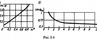
In physical terms, this device is designed to measure, at a certain point in the network, the angle between voltage and current. The scale of the device does not have any specific values, and the values are the cosine of the angle that is being measured. The measurement range is limited to extreme values of -0.5 and 0.5. The central value is equal to one. Next we’ll talk about why it’s designed this way.
During active load, when the current completely coincides with the available voltage, the device will display one. At the moment of collision of inductance and resistance, a voltage change occurs, which begins to break away from the current values.
The angle between current and voltage is directly proportional to inductance and its effect on the network. This naturally affects the power factor, which gradually decreases.
This is also demonstrated by the phase meter, the needle of which gradually deviates to the right value of the scale. This picture is typical for electrical networks to which high-power electric motors or devices containing inductive coils are connected.
Now that we know the principle of operation of the phase meter, we can move on. The picture described above may change. This is caused by the dominance of capacitance in the electrical network. At this time, the current value begins to exceed the same voltage value, and the phase meter needle begins to tend to the left side of the scale.
The direction of the slope of the arrow demonstrates the inductive type of the load, or its capacitive type. Based on this relationship, a deviation is obtained that describes the difference in current and voltage levels that formed in the network.
Application of phase meters
Such a device is an integral part when working with the electrical network. Most often, it finds its direct application in places where the relationship between current and voltage - network power - is influenced. Most often, these are just the settings for compensation, which are described above, but there may also be synchronous electric motors that are connected to the same circuit.
Also, the use of the device is necessary when working with synchronous generators, which are located at power plants. Let's consider both of these options.
Necessity of application
So, the need for phase rotation arises when working with a three-phase electrical network. Without strict phasing, there will be no guarantee that the direction of rotation of the rotor of an asynchronous motor will be correct. And without a clear direction, it is impossible to implement a specific technological cycle. This is precisely the problem that a phase indicator should solve.
Attention! Moreover, the scope of application of the device can be any, since the technological development of electrical networks does not stand still. It can be used both in the operation of ventilation systems and to ensure the operation of any pumps
With correct phasing, the sequential order will ensure the rotor moves in the given direction (for example, clockwise). To do this, the wires must be connected in a certain way. If the sequence of their connection is changed, then the rotation of the rotor will simply be disrupted. And then the entire technological process will be at risk. Up to and including the destruction of all equipment. However, when the correct phase sequence is restored, its operation should resume.
User manual
To understand the use of the phase meter, the main attention is paid to the operating instructions (included with the device). There are a few steps you need to take before you start
First, you should make sure that the operating conditions correspond to those recommended by the manufacturer, and the frequency range is in accordance with the metrological characteristics. After this, the circuit itself is assembled.
The phase meter is operated according to the following algorithm:
- First you need to read the instructions that come with the product. The document reveals the nuances and rules for using the device.
- Using the corrector, the arrow is set at the 0 mark.
- Make sure the buttons are not actuated.
- Connect the input probes to the required connectors.
- Press the key that supplies power to the device. Pay attention to the lighting of a special indicator.
- Wait a while for the device to warm up well. This is necessary to achieve maximum measurement accuracy. On average, the exposure time should be about 10-15 minutes.
- Find the input voltage.
- Press the button depending on the choice of external voltage and set the required frequency range.
- Press “>0<” for a pair of channels and “+”.
- Connect the channel probes to the 4-pole input.
- Set the limit switch to position “20”.
- Then move the meter needle to the “zero” position using the regulator.
Phase indicator
Author: admin, 05 Feb 2015
In this article we will look at the operation and diagrams of phase indicators, I will also tell you how to make a simple phase indicator with your own hands, why you need a phase indicator, how to use it and types of phase indicators.
Phase indicators are devices designed to determine the order of phase alternation
Please note - it is the order of alternation, i.e. not a single phase indicator will show you where phase A, B and C are, it will only show direct (A-B-C, B-C-A, C-A-B) or reverse (A-C-B, C-B -A, B-A-C) phase alternation. But in most cases this is enough, for example, if you connect a new input to the electrical panel and do the same alternation as the old input, then all the electric motors will rotate in the right direction
For phasing, for example, transformers, you will need to check the phases of the same name with a simple two-pole indicator. On ones with different names it will glow, on ones with the same name it won’t. But let's return to the phase indicators.
The industry produces a large number of different models of phase indicators, the most common brands were FU-2, EI5001 (analogous to I517m), VC-805... Instructions for using phase indicators EI5001 and VC-805 can be downloaded on the regulatory documents page.
Let's look at the FU-2 phase indicator shown in the picture above. The phase indicator has three terminals designated according to the phases “A”, “B” and “C”. Three alligator clips, or three probes, are connected to these clips; for convenience, electricians mark them with colored electrical tape in accordance with the color marking of the phases according to the PUE. (A - yellow, B - green, C - red).
They use the FU-2 phase indicator as follows : connect the “crocodiles” to the busbars or exposed phase wires, after which they briefly press the button located on the left side of the housing. If the white disk with slots rotates in the direction indicated by the arrow next to the disk (clockwise), then the order of phase alternation is direct. If the disk rotates against the arrow, then the phase sequence is reversed.
If you don’t have a phase indicator on hand, you can make a simple phase indicator with your own hands. To do this, we need 4 incandescent lamps of 220V, 25-60 W, sockets for them and a non-polar capacitor with a capacity of 2-3 μF.
Circuit of the simplest phase indicator
The diagram shows:
- L1-L4 - incandescent lamps 220V, 25-60 W.
- C1 - non-polar capacitor 2-3 µF, 500V.
- A, B, C - probes corresponding to phases A, B, C.
Circuit operation
If, when the probes touch the phases, the lamps of phase “A” (L1, L2) light up at full incandescence, and the lamps of phase “B” (L2, L3) light up at half-incandescence, then the order of phase alternation is direct.
Scheme at work
Of course, such a phase indicator turns out to be quite bulky and inconvenient, so let’s consider another phase indicator circuit, somewhat more complicated, but much smaller.
It is possible, in principle, to modify this phase indicator by replacing the chains of lamps with chains of a series-connected quenching resistor and a light bulb from a flashlight, or by adapting LEDs.
Phase indicator circuit on a thyristor
phase indicator on a thyristor
The diagram shows:
- R1 - resistor C5-35(PEV) 5 W, 1.8 kOhm.
- R2 - MLT-1 resistor, 10 kOhm.
- D1 - diode KD105V.
- VS1 - thyristor KU202N.
- L1 - lamp МН26-0.12.
Circuit details
Resistors can be of any brand with a value close to the specified one. R1 for a power dissipation of at least 5 W (depending on the lamp used), R2 for a power of at least 1 W.
Diode D1 can be taken from brand KD209.
The thyristor can be replaced with T112-10-5, T112-25-10.
Circuit operation
Terminal “0” is connected to zero, Terminals “A” and “B” are connected to any two phases. If the light bulb glows brightly, it means the terminals are connected to the same phases “A” and “B”, but if the light bulb lights up dimly or does not light up at all (can be adjusted by selecting the value of R1), then the terminals are connected in reverse.
Without going into details, I will say that such operation of the circuit is due to different opening angles of the thyristor; if you are interested, you can “rummage” on the Internet.
It will be interesting to read:
Battery charger
Installation of a pass-through switch
Sockets in series
Categories:
The sequence of manufacturing a simple phase indicator
There is a circuit for a simple phase indicator that can be used in a three-phase industrial network without fear of electric shock or damage to the device. The diagram is presented below:
To work you will need the following elements:
- 3 connecting terminals, made of the “crocodile” type.
- 2 resistors with a resistance of 10 kOhm and 18 kOhm.
- Diode type KD105V. It is possible to replace the element with a diode from the KD209 series.
- Thyristor type T112-25-10 (25A 1000V). It is possible to replace the element with VS-25TTS12-M3 (25A 1200V).
- Incandescent lamp, voltage 26 V and current 0.12 A.
- A small piece of wire with a cross-section of 1 mm² for internal installation of the circuit.
- 3 pieces of wire with a cross-section of 1.5 mm² of such length that it is enough to comfortably measure the phases with your own hands.
- Plastic case.
The sequence of installing the electrical circuit of the phase indicator with your own hands:
- Connect the elements of a diode, a thyristor, two resistors and an incandescent lamp using soldering according to the above diagram.
- Secure the soldered parts in the plastic case. You can use epoxy glue, but not on the elements themselves, which can heat up during operation.
- Use a thin drill to drill 3 holes in the body and run 3 identical pieces of wire with a cross section of 1.5 mm² into them - these will be measuring probes. Secure the wires with epoxy - since the conductors are insulated, excessive heating is not a problem here.
- Attach crocodiles to the ends of the measuring probes. For greater reliability, they can be soldered.
- In the top cover of the plastic case, drill or cut a hole for a socket for a signal lamp. The cartridge is securely secured to the inside of the housing using epoxy glue.
- Secure the top housing cover with four small self-tapping screws.
- Checking the device on a line in which the phases are clearly located correctly.
This phase indicator has a significant advantage over expensive industrial models - simplicity. The cost of all elements (including consumables) required for assembly is very low and will not hurt your pocket. Any novice electrician, even those who picked up a soldering iron for the first time, can assemble and solder such a circuit.
The operating principle of the devices is very simple: phased lines turn on the lamp on the device body. Correct alternation - the lamp glows brightly, incorrect - very dim or does not glow at all. You can choose the simplest case of the device, but only from insulating plastic or any other material that does not allow electric current to pass through.
Power factor control
How it works in practice. If you see that the cosine index is close to one, you should understand that the ratio of energy that is consumed is used as accurately as possible for useful work. If the arrow goes to the left, electricity begins to be spent on useless heating of devices connected to the network, such as electric motors, windings of various transformers, or simple cable lines. This is accompanied by a decrease in network voltage, which entails an increase in power consumption by all equipment to ensure standard useful operation.
We figured out what a phase meter is, as well as how it works and what it shows. Acceptable values of the device will be coefficients in the range of 1-0.95, with a deviation towards inductance, to the right. But, if the value turns into inductance, then how to compensate for this?
This is not a problem, since at all electrical substations special batteries of capacitors are installed, which compensate for the so-called reactive power. Just from the description it is not difficult to understand what such devices do. They equalize and compensate for the inductance present in the network, which creates negative resistance, and therefore level the angle formed between the voltage and current axes, which will later be demonstrated by a device such as a phase meter.
This approach also has its downsides. If such capacitors have a constant capacitance, this leads to problems that arise when connecting to the network for users who have a small level of inductive reactance. In this case, the power ratio changes.
In such a scenario, compensation becomes not only ineffective, but also harmful in places. The principle of operation of the phase meter is to detect such problems. If not necessary, compensation installations are designed in such a way that they can operate in automatic mode and, if not necessary, do not interfere with the electrical network.
This is controlled by special machines that turn on the installation only at a certain value of the cosine of the angle. This happens by changing the battery capacity, thereby adjusting the desired level of current and voltage ratio in the network. Such installations are very powerful and operate under a voltage of several thousand volts.
Automatic systems are usually installed in large enterprises where there is a significant consumption of electricity due to a huge number of high-power devices. In local substations, which are located in residential areas of the city and in rural areas, the installation capacity is calculated during installation, after which it does not change.
Briefly about the phase meter
When the device is connected to the measurement circuit, it is connected simultaneously to the current and voltage circuits. If it is necessary to work with networks that have three voltage phases, then the device is connected simultaneously to all these voltage phases. The current connection is made to the secondary windings of the transformer.
The device uses a simplified connection diagram. Therefore, it will not be difficult to figure out the purpose of the phase meter yourself. The current connection is made in two phases, so the third phase is determined based on the addition of vectors of only a pair of currents (meaning the measured phases). Also, the purpose of the phase meter is to measure the power factor. This device in simple language is also called a cosine meter.
At the moment, there are two types of phase meters, the scope of which is to determine the power factor. This is a digital and electrodynamic device. Let's look at them in more detail.
What is a phase meter
A phase meter is a measuring device that measures the phase shift angle in relation to two electrical oscillations with a constant frequency. Often, this device is used to determine the angle in a three-phase electrical circuit.
When connecting this device to the circuit being measured, it is connected to the voltage circuit and also connected to the electrical network that is being measured.
In a three-phase line, the device is connected to all phases, and in terms of current - to the windings of the transformer of three phases. There is a simpler circuit when the voltage is also connected to three phases, and the current is connected to two phases of the secondary winding.
Briefly about the phase meter
To carry out measurements, the phase meter is connected to voltage circuits, which act as a reference point, and a current circuit, which shows the position of the measured vector. When operating on a 3-phase network, it may be necessary to connect to all phases.
The peculiarity of modern devices lies in the simplified principle of use, so understanding the features and subtleties of using a phase meter will not be difficult even for an inexperienced specialist.
The measurement is made for two phases, after which the last phase is calculated based on vector addition. In addition, the phase meter is often used to measure the cosine phi, as mentioned at the beginning of the article.
Synchronous generators
Personnel who are allowed to work with synchronous generators do not need instructions for using the phase meter, since they are qualified electricians. Such people know that the power of a synchronous generator is directly proportional to the power of the rotor, in particular to the level of current that is excited in it.
During their work, specialists must monitor and constantly monitor changes in the value of the cosine of the angle, which is shown by the phase meter. Based on this value, adjust the current level inside the circuit. Usually, during normal operation, an automatic system is responsible for all this, which regulates the required values.
But a specialist is needed during emergency situations, such as starting a generator for operation, or during its failure, when you need to reboot and start it manually. For this purpose, a generator panel is used, in which a phase meter is mounted.
In this case, you do not need to know how to correctly connect the phase meter, since it is already connected to the circuit. It constantly monitors changes in the network, and when the arrow moves to the right, a warning is triggered, because in such a situation, significant overheating of the generator and its stator winding can occur.
If the arrow points to the right and the load switches to capacitive, the alarm also triggers. This is because in this mode the generator begins to independently consume energy from the network, and this is already an emergency situation in operating mode.
Synchronous electric motors
As with the previous option, the power of the engine, and therefore the productivity of its operation, depends on the voltage that is excited in the network. This task lies with the excitatory station, which regulates the level of current excitation. Such an electric motor has a special operating mode, during which it is capable of releasing so-called reactive energy into the network, thereby taking on the role of a device that compensates reactive power.
Popular models on the market
The most popular phase meters are devices of the D5721 and D5782 brands.
This type is used in single-phase current-carrying networks, the frequency of which is 50-60 Hertz. Weight more than 6.5 kg. Performs measurements of voltage and current phase displacement.
Megeon 40850 has small dimensions. The measurement process takes place in a fairly short time, while its accuracy is high. This device is equipped with LEDs, alligator clips, and a built-in buzzer.
The invention weighs 810 grams, second class safety. It is capable of operating at air temperatures from -10 to +40 degrees, and takes measurements in electrical equipment under voltage from 200-400 volts.
Ts302 takes measurements in a three-phase line, and the current frequency can vary from 50 to 10,000 Hertz. This type easily tolerates vibration.
Basic principles of classification of phase meters
As an electrical measuring device, phase meters are classified according to several criteria:
- Based on the design:
- analog (electromechanical, electrodynamic);
- digital (electronic).
- By number of phases:
- single-phase;
- three-phase.
Single-phase instruments are designed to determine the phase angle in single-phase circuits, and 3-phase instruments allow measurements to be made in full-wire circuits. Structurally, such devices are not much different, the difference is that in a single-phase device all the moving frames are located relative to each other at an angle of 90 degrees, and in a 3-phase device - at 60 degrees.
Measuring cos φ at industrial frequencies is carried out using electromechanical devices with direct reading, which use a logometer (ferrodynamic, electromagnetic, induction, electrodynamic) as a measuring mechanism. The deviation of the moving part of the ratiometer is determined by the phase shift of the corresponding current and voltage.
For a wide range of frequencies, electronic counting meters of time intervals from the moment of passage of related phase oscillations through 0, and graduated phase shifters in an ensemble with indicators of zero phase difference (for example, phase detectors) are used as a phase meter.
Electronic type phase meters are made in the form of a separate unit. Its front panel displays a microammeter, the scale of which is graduated in degrees, a power supply switch, and input terminals for the measured signals.
All components of the device are mounted on a printed circuit board made of foil fiberglass and secured to the measuring clamps of a microammeter.
The board is connected to the input terminals using a shielded wire, which ensures high noise immunity.
The error of the electromechanical phase meter is 1-3°, electronic - 0.06-0.1°.
Let's consider several phase meters from different manufacturers:
VAF-A(M) produced by PARMA
The price is about 31 thousand rubles.
Voltamperphasometer of a new generation.
Current measurement from 0 to 3000 A, graphic indicator, connecting the device to a PC via USB, saving data on a PC, memory for 100 measurements, built-in clock, “Recorder” mode, battery power.
Distinctive features of the VAF-A(M) device:
- current measurement from 0 to 3000 A in four ranges (equipped with three types of current clamps);
- graphic indicator;
- connecting the device to a PC via USB interface for updating software and charging batteries;
- access to recorded data using standard MS-Office tools; work with the device as an external storage device;
- tree-like menu system for device settings, the ability to access and edit them using an indicator and a two-button keyboard;
- memory for 100 measurements;
- automatic detection of the type of connected clamps;
- built-in clock;
- “Recorder” mode – recording of measured channels (current and voltage) and two reference channels as discretes with a specified averaging time and recording interval; recording format - CSV;
- calibration of the device in an interactive automated mode using only the internal software of the device;
- LCD contrast and backlight control;
- giving a sound signal in case of malfunctions, overload or reduction in supply voltage.
2. Volt-ampere phase meter VFM-3 manufactured by Chelyabenergoprobor
Price about 50 thousand rubles.
Voltamperphasometer VFM-3 is a small-sized, fully automated, universal device. Designed to measure the effective value of three phase and three linear voltages and the effective value of the strength of three alternating currents with simultaneous calculation of active, reactive and apparent powers in three circuits, measurement of frequency, phase angle between currents and voltages of the same phases.
The VFM-3 device displays a graphic image of a vector diagram of the controlled circuit.
The VFM-3 volt-amperephase meter can be used for complex tests of protection of generators, transformers, lines, in current and voltage transformer circuits, adjustment of phase-sensitive relay protection circuits, etc.
Distinctive features of VFM-3
- The most compact and lightest (0.3 kg) of modern 3-phase voltammeters.
- All main measurement results are displayed simultaneously on the 4.3” color indicator, and a vector diagram can be displayed.
- Measurement of AC current within 0...50 mA without breaking the circuit. In this case, the absolute error does not exceed ±1 mA.
- Measurement of phase shift between voltage and current, including currents less than 50 mA. The absolute error at a current of 50 mA or more is within ±1 degree, at a current of 15 mA - no more than ±3 degree.
- Carrying in a bag is carried out with the wires plugged into the measuring unit. To switch to the working position, you do not need to plug in the connectors; you just need to open the bag.
3. RETOMETER-M2 produced by NPO "Dynamics"
Price about 50 thousand rubles)
This is a three-phase multifunctional and fully automated device of a new generation, designed for measuring parameters in three-phase and single-phase electrical circuits with an operating frequency of 50 Hz.
The device is an indispensable assistant for personnel of relay protection and automation services of power enterprises, chief power engineer services, industrial enterprises and many other specialists involved in the operation of electrical installations.
Distinctive features of the RETOMETER-M2 device:
- high sensitivity, calculation of all parameters begins from the moment of actual measurement of current and voltage (from 1 mA and 5 mV);
- wide voltage measurement range up to 750 V, which allows operation in 660 V networks;
- wide measurement range of alternating current up to 40 A, which in some cases makes it possible to measure the primary current;
- small-sized current clamps included in the delivery set allow you to measure current in the most inaccessible places (for example, in modern panels and cells);
- optional RET-DT current clamps expand the current measurement range to 30 kA;
- true rms current and voltage measurements (TRUE RMS);
- measurement of the phase shift angle is performed at the fundamental harmonic, while noise and signal distortion do not affect the measurement accuracy;
- possibility of fixing measured parameters on the screen in the “HOLD” mode;
- a simple way to determine the polarity of the windings of current transformers and voltage transformers;
- safe check of the integrity of connections in the “Dialing” mode, which does not turn on in the presence of external voltage;
- high-contrast indicator that allows you to display a large amount of information;
- Li-ion battery provides long battery life, fast charging and no memory effect;
- automatic shutdown of the device.
Another interesting video about VAF Retomert M2:
User manual
The best guide to explain how to use a phase meter is its instruction manual, which must be included in the package. Before starting work, you need to perform a number of sequential actions
It is important to first make sure that the frequency range corresponds to the metrological characteristics, and also that the external conditions correspond to the operating conditions. After this you can already assemble the circuit
So, the operation of the phase meter should be carried out in the following sequence:
- Initially, you must carefully read the operating instructions supplied with the device, where you can learn about its purpose and rules of use.
- Using the corrector, the arrow is set to the zero value mark.
- You need to make sure that all the buttons are in the released position.
- Connect the input probes to the appropriate connectors.
- Now you need to enable the network button. At this moment, a special indicator should light up.
- Next, you should not immediately start measurements, since the device needs time to warm up. This procedure will take approximately a quarter of an hour.
- Now we find the signal voltage from the input side.
- Press one of the buttons depending on the desired voltage and set the required frequency range.
- After that, press “>0<” of two channels and “+-“.
- Channel probes are included in the four-pole input.
- Next, set the limit switch to position “20”.
- After this, we set the arrow of the meter itself using the “>0<” regulator to the zero position.
It is much easier to use a digital phase meter. The video review below clearly shows the operation of this device:
Now you know how to use a phase meter and what this device is needed for. We hope that the material provided was useful and understandable for you!
You probably don't know:
- What is the danger of phase imbalance in a three-phase network?
- How to use a phase indicator
- How to distribute the load across phases
Source: Samelectrik.ru
Main technical characteristics of a digital phase meter
1) operating frequency range 0.002…2000, kHz;
2) input voltage range 0.002…2, V;
How to check the voltage with a multimeter in the network: measuring the voltage in a 220 volt outlet
3) phase difference measurement limits ±180°; 0…360°.
4) the main error in measuring the phase difference (with relative instability of the signal frequency of no more than 10–4 per 10 minutes), where j is the measured phase difference in degrees; A
– ratio of input voltages, dB.
5) the input resistance of the device is more than 1 MOhm, the input capacitance is 30 pF.
Operating principle. In the F2-16 phase meter, the measured phase shift is converted into a time interval (Fig. 3.4, a
and b
). With the help of forming devices (FU), short-term pulses are generated from the voltages under study at the moments when the voltages pass through 0 V
Rice. 3.4. Block diagram and timing diagrams of a phase meter with conversion of the phase shift into a time interval
side of increase. These pulses arrive at the inputs S
and R
trigger T, and rectangular pulses are formed at its output. The duration of the trigger pulses t is proportional to the measured phase shift: . The average voltage at the trigger output, proportional to the measured phase shift
,
measured by a built-in digital DC voltmeter. In this case, the pulse amplitude is selected in such a way that the voltmeter readings numerically coincide with the phase shift, expressed in degrees.
With this method of measuring the phase shift, a systematic error may arise due to the asymmetrical limitation of the voltages under study in the FU. In this case, the voltage at the output of the limiter, for example in FU1, will have a constant component (Fig. 3.4, c
). The differentiating circuit included in the FU does not allow a constant component to pass through, therefore the moments when the voltage passes through zero are shifted (shown in Fig. 3.4, c
arrows). Changing the t interval leads to an error in measuring the phase shift.
Structural scheme. The F2-16 phase meter is made according to a two-channel scheme; the reference channel (OC) and the measuring channel (IC) are identical (Fig. 3.5). To eliminate the error due to asymmetrical limitation, the phase meter uses two triggers. The limiter amplifiers are made according to a push-pull circuit, so their output voltages u
3,u
4 and
u
5,
u
6 are antiphase (Fig. 3.6).
Rice. 3.5. Block diagram of phase meter F2-16
The role of differentiating chains is performed by level discriminators. Discriminators OK are triggered when voltage u
3,u
4 in the direction of increase, and the IR discriminators are triggered when voltages
u
5,
u
6 pass through 0 in the direction of decrease.
Trigger T2 is switched by a positive pulse u
7 and a negative pulse
u
9. Trigger T2 is switched by pulses
u
8 and
u
10, respectively, which are shifted by half a period relative to
u
7 and
u
9. Rectangular pulses
u
11 and
u
12 with an amplitude of 6 V with T1 and T2 are added in the adder, forming
u
13. A bias voltage of 12 V is also supplied there. A direct current amplifier (DCA) separates the DC component and changes its polarity, after which the voltage is measured by a digital voltmeter.
If in the first channel, for example, the limitation is asymmetrical, then the pulses u
7 and
u
8 are shifted, as shown by the arrows in Fig.
3.6. u
pulse will become shorter, and the
u
12 pulse will become longer, so the resulting constant component will remain unchanged.
Rice. 3.6. Timing diagrams explaining the operation of the F2-16 phase meter
The F2-16 phase meter has a phase shift measurement mode of ±180°. In this mode, using the voltage switch u
7 and u
8 are swapped, the adder is supplied with a bias voltage of not –12, but –6 V. Voltage graphs for this mode are shown in Fig. 3.6 on the right.
Necessity of application
There are situations during which the connection of a three-phase network must be carried out in phase rotation order. The fact is that the direction in which the rotor rotates when connecting an asynchronous motor to the network cannot be accurately indicated unless we strictly follow the phasing procedure.
For example, when it comes to operating a fan for the corresponding system or a drive for operating a pump, it is necessary to clearly know the direction of rotation. This ensures the execution of the technological cycle. Therefore, it is important to maintain consistent connections in this case. In order to solve this problem, you should resort to using a special device called a phase indicator. This allows you to understand why it is needed. The scope of application of the phase indicator is quite wide and is constantly growing.
If the phasing is set correctly, then the order of the phases goes from A to B and ends with C. The same order determines the direction of rotation of the engine. For example, if the wires that power the windings are connected in the correct order, then the motor rotor operates conditionally in a clockwise direction. However, in a situation where two of these phases are changed, the direction of rotation of the rotor will be disrupted. Then the technological process in which the engine is involved will simply be disrupted. This will cause the equipment used in the drive to be damaged and fail. After this, if you perform the reverse procedure with the phases, the engine operating order will return to normal and the process will be correct.
APPLICATION OF ELECTROMAGNETIC RELAYS
Perhaps, relays operating using the electromagnetic principle are most widely used in the field of distribution and production of electrical energy.
Relay protection of high-voltage lines ensures trouble-free operation of substations and other connected equipment.
The control elements used in relay protection installations are designed for connection switching at operating voltages reaching several hundred thousand volts. The widespread use of relay protection for high-voltage lines is due to:
- high durability of relay elements;
- quick response to changes in parameters of connected lines;
- ability to work in conditions of high intensity electromagnetic fields and insensitivity to the appearance of parasitic electrical potentials.
Also, through relay protection installations, power lines are backed up and damaged sections of the power network are immediately taken out of service, for example, when a line is shorted to ground or live parts are broken. To date, more reliable means of protecting power lines than relay protection have not yet been invented.
In addition, currently the electromagnetic type of relay is widely used in control systems for production and conveyor lines. Most often, this type of control systems is used in industries with high parasitic potentials making it impossible to use semiconductor control systems.
For example, there is a known case when, during the modernization of conveyor line control systems at one of the elevators, new equipment built with the latest semiconductor elements constantly failed.
As it later turned out, the cause of the breakdown was static electricity that occurs when grain moves along the conveyor belt, and since the potential equalization system was not provided in these premises, the question arose about moving the control panel to a protected room.
This was associated with enormous material costs. As a result, it was decided to switch to relay control units that are insensitive to static voltage.
The operating principles underlying the functioning of electromagnetic relays are used in remote load control devices - starters or contactors.
The principle of operation of these devices is in many ways similar to the operation of relays, with the only difference being that these devices are designed for switching power circuits, the current strength in which can reach 1000 A, and in the case of particularly powerful installations, even higher.
In addition to low-voltage equipment, relay units are used to control capacitor units, which are used for smooth starting of high-power electric motors.
But the most significant application of electromagnetic type relays is their use in the first electronic computers, as logical elements capable of performing the simplest logical operations. Despite the low performance, these first computers were superior in reliability to the next generation of tube-based computer systems.
The simplest examples of using an electromagnetic relay in everyday life are control relays in various types of household appliances: refrigerators, washing machines, etc.
2012-2020 All rights reserved.
The materials presented on the site are for informational purposes only and cannot be used as guidelines or regulatory documents.
Kinds
All phase meters according to the operating principle are divided into three types:
- Electrodynamic;
- Digital;
- Electromechanical.
The first two types are in greatest demand, but it is recommended to use digital devices. They are characterized by greater accuracy and low noise levels.
According to the number of phases, phase meters are:
- Single-phase - for carrying out measurements in a 1-phase circuit.
- Three-phase - for 3-phase circuits.
Electrodynamic
Until recently, electrodynamic (electromagnetic) phase meters were in greatest demand. Structurally, this device consists of a simple ratiometric mechanism that allows accurate measurement of phase displacement.
The device has two frames that are rigidly connected to each other. The angle between the mentioned elements is 60 degrees. The frames are mounted on axes fixed to support units. Thanks to this feature, the device has no mechanical resistance.
The device has a special element that rotates through an angle that characterizes the magnitude of the current phase shift. Using a linear scale, the technician can record the measurement and determine the current offset setting.
The electrodynamic phase meter is based on a fixed current coil, as well as two more similar, but movable elements. The displacing coils have their own currents flowing, which contributes to the appearance of a magnetic flux in all coils - moving and stationary.
When the coil flows interact, a pair of rotating moments appears, the magnitude of which depends on the distance between the moving elements of the device. The mentioned moments have different directions, which are opposite in magnitude.
The torque indicators depend on the currents flowing in the moving coils, as well as on the current level in the fixed coil. In addition, the mentioned indicators depend on the design features of the coil and the angular phase shift.
As a result, the moving element of the phase meter rotates under the influence of the mentioned moments until a situation where equilibrium does not arise, that is, the moments become equal.
The phase meter itself often has a gradation that allows you to accurately measure the power factor.
The advantages of the device are reliability, high accuracy of readings, and affordable price.
The disadvantage is the dependence of the measured parameters on the frequency indicator. Another disadvantage is the increased power consumption from the source being studied.