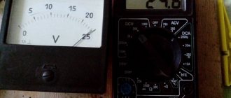
Ammeters are used to measure the strength of direct or alternating electric current. The graphic designation of this device on electrical diagrams is a circle with the letter “A” placed inside. This measuring device determines the strength of electric current in amperes, milliamps or microamps. An ammeter is connected in series to the open circuit.
Physical quantity
An ammeter measures the physical quantity Ampere.
Ampere determines the strength of current. Current strength is the speed of passage of charged particles with a volume of 1 Coulomb through 2 parallel conductors 1 meter long. This law was discovered by the French physicist Andre-Marie Ampère.
The first functional device for measuring current was invented by Johan Schweiger in 1820. At that time it was called a galvanometer.
Ammeter
An ammeter is an instrument that is used to measure current. It is a device with a scale and arrow. Inside the device there is a metal or magnetic frame. A coil is installed inside the frame. The operating principle of the ammeter is as follows:
- An electric current passes through the coil.
- The current creates a magnetic field that moves the needle on the instrument.
The measurement has almost zero error, due to the fact that the resistance of the ammeter is very small. It cannot influence or change the passing voltage parameter.
The display of each mechanical ammeter has a scale. The scale shows the ammeter's measurement limit. Such devices can measure from a high value of 10 Amperes, to the lowest in units of up to 200 microamps. When working, it is necessary to take into account the measurement limit. It can be expanded by connecting a transformer or a shunt element.
When working, you also need to know what current the ammeter is designed to measure. They are: constant and variable. On the scale of each device there is a designation for what type of voltage the device is intended for.
A DC ammeter is used to measure current in devices that operate through a step-down transformer and diode bridge. Consumers are often equipped with ammeters to monitor the load. It is very easy to find an ammeter in the circuit diagram - it is indicated by the letter “A” enclosed in a circle.
AC ammeters are used to measure the load of household or high-voltage networks. They operate by connecting a transformer or shunt resistor in parallel with a high resistance value. In this way, it is possible to reduce the load on the measuring device itself. Next, the main types of ammeters will be discussed.
Accuracy class
This is the main characteristic of an ammeter, which, according to the still in force Soviet GOST 1845-59, determines the limits of possible errors.
For all electrical measuring instruments to which it belongs, the accuracy class (Cl) is indicated in numerical form by the value corresponding to the maximum permissible reduced error δpr, in%.
All electrical ammeters are divided according to accuracy into 8 classes, and then into groups, which is an important feature of their classification:
- Exemplary: 0.05–0.1–0.2;
- laboratory: 0.5–0.1;
- technical: 1.5–2.0–4.0.
Note! All devices with an error exceeding 4% are extracurricular.
Exemplary ones are used in electrical measuring processes to determine the accuracy class of technical and laboratory ammeters. Laboratory ones are used in scientific and technical processes during electrical engineering studies of control of operating modes, for example, in boiler houses, hydroelectric power plants, thermal power plants and nuclear power plants.
Important! On the ammeter panel, the accuracy class is indicated in circles, squares and asterisks. If it has an uneven measurement scale, Kl is indicated by a broken line.
Varieties
The described measuring device has come a long way and many upgrades. Today, there are analog and digital types of these devices. There are also: magnetoelectric, electromagnetic, electrodynamic, ferrodynamic types of ammeters. Each type has its own characteristics of the device and its operation. Each type will be described in more detail below.
Magnetoelectric device
A special feature of these devices is a magnetic coil, which moves when exposed to electrical voltage.
All such devices are used to measure direct current. The advantage is very high sensitivity and measurement accuracy.
Electromagnetic
The device does not have a rotating coil in its design.
The change in the angle of the hand on the dial occurs due to the magnetic field acting on the cores of the coils. Similar ammeters are of a universal type. With their help you can measure the strength of direct and alternating current. The main disadvantage is the presence of error.
Electrodynamic
The device is similar in design to a magnetoelectric one. The main difference is the presence of moving and fixed coils.
When connected, the magnetic fields of the two elements influence each other, which leads to a change in the position of the arrow. The device is quite accurate. The only drawback is that its operation can be affected by extraneous magnetic fields.
Ferrodynamic
This measuring device is considered the most accurate. The ammeter device includes a ferrite wire, a metal core and a coil.
The device operates on the principle of coil rotation due to the formation of a magnetic field. The main feature is complete independence from the influence of extraneous magnetic fields. Has high sensitivity.
Electronic
With the development of electronics, ammeters began to be produced in digital variations. The two most famous are a simple household multimeter and a clamp meter tester.
The main advantage of such devices is the simplicity and versatility of current measurement. They are not susceptible to external magnetic fields, are not afraid of shocks, minor damage and shaking. Close to an ideal ammeter.
For information! An ideal ammeter is an ammeter with zero self-resistance.
All the devices described are used to this day in instrument making, laboratories, industry and by individual enthusiasts.
How does it work
The following is an analysis of the operating principle of an ammeter and a voltmeter, since they are similar to each other.
If we consider a simplified classical circuit of an ammeter, we can highlight the following principle by which it works. A steel armature with an arrow is installed in parallel with a permanent magnet, thereby obtaining magnetic properties. The anchor is located along the power lines. This position corresponds to the zero mark on the instrument’s definition scale.
When current passes through the bus, a magnetic flux is created. The flux lines are perpendicular to the forces in the permanent magnet. The magnetic flux acts on the armature, which tends to turn 90 degrees, but the rotation is prevented by the flux of the permanent magnet. The difference in magnetic fluxes causes the needle to deflect by the amount of current.
Examination
The accuracy of any measuring instrument depends on its calibration. A stamp was placed on analog devices, which confirmed testing in the laboratory. Modern digital multimeters with current measurement mode do not have such stamps, and they have not been tested. Many novice electricians do not know how to test an ammeter. To check the measurement accuracy you must:
- Connect the device under test in parallel with the reference one. It is advisable that this be a mechanical ammeter.
- Connect a variable resistor to the circuit.
- Connect a resistor with high resistance to the variable resistor.
- Connect the circuit to a power source.
- Using the variable resistor “R2”, set the voltage threshold so that the needle of the mechanical device is exactly in the middle of its scale.
- Turn on the multimeter to measure current.
- Compare the results.
- Use a variable resistor to regulate the deflection of the needle of a mechanical device towards the maximum.
- If there is a deviation for each subsequent value, compare the test results.
This way you can check the accuracy of the digital multimeter when measuring current. To increase the load, you can add several incandescent lamps to the circuit. The following will give a detailed description of how to use an ammeter.
Voltage measurement. Voltmeter.
If there were no voltmeter in the circuit, the current through the resistors would be the same and determined by Ohm’s Law as follows:
As with the ammeter, there is a special method that allows you to increase the voltage measurement limits of the voltmeter. To do this, it is necessary to connect an additional resistance in series with the device, the value of which is determined by the formula:
This will cause the voltmeter to be n times less than the measured voltage. As usual, let's look at a small practical example:
Here we added additional resistance R_3 to the circuit. Our task is to measure the voltage across the resistor R_2:\medspace U_2 = R_2\medspace I_2. Let's determine what result the voltmeter will give us when turned on in this way:
Let's substitute the expression for calculating the resistance of the additional resistor into this formula:
Thus: U_B = \frac . That is, the voltmeter readings will be n times less than the voltage value that we measured. So, using this method, it is possible to significantly increase the measurement limits of the voltmeter.
At the end of the article, a few words about measuring resistance and power.
In general, this is probably the end of today, stay tuned!
Expert opinion
It-Technology, Electrical power and electronics specialist
Ask questions to the “Specialist for modernization of energy generation systems”
How to connect an ammeter Current strength I is a scalar quantity equal to the ratio of the charge q passing through the cross section of the conductor to the time period t during which the current flowed. Ask, I'm in touch!
Connection
Next, we will consider 2 options for measuring current strength: for a circuit with alternating and direct voltage. Before connecting the measuring device, you need to remember that any ammeter has a very low intrinsic resistance. It is impossible to measure the current strength without a load from a third-party element. This is especially important when working with alternating voltage. All instructions will be given using the example of a digital multimeter in current measurement mode.
Alternating current
In order to measure the AC current you need to:
- Switch the multimeter switch to AC current measurement mode.
- Select the largest value.
- Connect the red measuring probe to the “10–20 A” socket, depending on the type of device.
- Insert the black probe into the “COM” socket.
- Connect the power cord to the transformer (it is forbidden to plug it into an outlet).
- Connect one contact of the test lamp to the “+” terminal from the transformer.
- Connect the second contact from the lamp to the red measuring probe of the tester.
- Connect the black test lead to the second terminal of the transformer.
- Apply voltage to the transformer.
The ammeter will show the consumption value of the test lamp in amperes. Connecting test leads without a lamp is strictly prohibited.
Alternating current can also be measured using a clamp meter. To do this you need:
- Remove the control probes from their sockets.
- Switch the tester to current measurement mode.
- Grasp the wire core with pliers.
The ammeter will display the consumption value.
D.C
To measure direct current, a parallel connection of the tester is also used. Next you need:
- Switch the device to DC voltage measurement mode.
- Insert the red test lead into the “mA” socket.
- Leave the black one in the “COM” socket.
- Select the largest measurement parameter in milliamps.
- Connect the minus input of the device being measured to the minus terminal of the battery.
- Connect the “+” input of the device to the black measuring probe.
- Connect the red test lead to the “+” terminal of the battery.
In this way, you can find out the threshold consumption of an appliance or device operating on constant voltage.
Safe work rules
When using the device, the following safety precautions must be observed:
- The device must not be shaken or dropped.
- If the arrow on the device goes off scale, you must immediately open the circuit.
Diagram of correct connection of the device
Connection rules:
- Connect the positive terminal of the device to the positive terminal of the current source. If the circuit consists only of a current source, the device cannot be connected to it!
- The ammeter is connected in series. The connection occurs with the element whose current strength needs to be measured.
- The device must be in a horizontal position.
Knowing the connection rules and types of devices, you can choose the most suitable ammeter for measurement.