Definition
Vasiliev Dmitry Petrovich
Professor of Electrical Engineering, St. Petersburg State Polytechnic University
Ask a Question
An ammeter is an electrical measuring device designed to record the strength of direct or alternating current flowing in a circuit - that is, a device for measuring current.
The ammeter is connected in series with the section of the electrical circuit where the current is supposed to be measured. Since the current that it measures depends on the resistance of the circuit elements, the resistance of the ammeter should be as low as possible (very small). This allows you to reduce the influence of the current measuring device on the measured circuit and increase their accuracy.
The instrument scale is calibrated in µA, mA, A and kA, and depending on the required accuracy and measurement limits, a suitable device is selected. An increase in the measured current is achieved by including shunts, current transformers, and magnetic amplifiers in the circuit. This allows you to increase the limit of the measured current value.
Instruments for measuring current strength
If a current flows in any conductor, then it is characterized by such a value as “current strength”. The current strength, in turn, is characterized by the number of electrons that pass through the cross-section of the conductor per unit time. But we all went to school and know that there are billions of billions of electrons in a conductor and counting the number of electrons would be pointless.
Therefore, scientists got out of this situation and came up with a unit for measuring current strength and called it “Ampere”, in honor of the French mathematical physicist Andre Marie Ampere. What is 1 Ampere?
If the current in a conductor is 1 ampere, then in one second a charge equal to 1 Coulomb passes through the cross-section of the wire. Or in simple terms, all electrons in total must give a charge of 1 Coulomb and they must pass through the cross section of the conductor within one second.
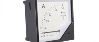
Ammeter scale
If we take into account that the charge of one electron is 1.6x10⁻¹⁹, then we can find out how many electrons are in 1 Coulomb. But in order to measure amperes, scientists came up with a device and called it an “ammeter”.
Ammeter is a device for measuring current in amperes. The ammeter scale is calibrated in amperes, kiloamperes, milliamperes or microamperes in accordance with the measurement limits of the device. The ammeter is connected in series to the electrical circuit; to increase the measurement limit - with a shunt or through a transformer.
An ammeter is a device for measuring current in an electrical circuit. Any ammeter is designed to measure currents of a certain magnitude. In electronics, we mainly operate with microamps (µA), milliamps (mA), and also amperes (A). Therefore, depending on the magnitude of the current being measured, current measuring instruments are divided into ammeters (PA1), milliammeters (PA2) and microammeters (PA3).
dual voltmeter-ammeter
Measurement of AC current values
Knowing the current flowing through a certain section of the circuit is quite important. This helps to calculate the cable cross-section and avoid overheating of the conductors. This article will help novice electricians understand the nuances of operation and connection of the measuring device. But first, let's remember a few basics from the school curriculum.
As you know, an ammeter is a measuring device that allows you to determine the strength of direct and alternating current in an electrical circuit. Depending on the intended scope of application, the scale of the measuring device is calibrated in amperes, micro- or milliamps. To measure large quantities, a device is used whose scale is divided into kiloamperes.
Digital ammeter circuit
The hundredths will correspond to the fourth display, which we don't have, for example "03", if we are looking for a zero on top, the error will be larger, for example "08". Repeating the process three times should be ideal at best.
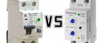
It will be interesting➡ What is a digital ammeter and why is it better than a regular one?
Ammeter connection diagrams
Figure - Diagram of direct connection of an ammeter
Figure - Scheme of indirect connection of an ammeter through a shunt and a current transformer
Ammeter device
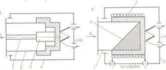
To understand the need to turn on the ammeter through a shunt, let us briefly recall its structure.
Inside the field of a permanent magnet there is a coil - a frame. The measured current flows through its turns. Depending on the value of the measured parameter, the position of the coil relative to the constant magnetic field changes. The arrow of the device is rigidly fixed on its axis. The greater the current being measured, the more the needle deflects.
So that the frame can rotate, its axis is secured in the thrust bearings, or hung on guy wires. When using thrust bearings, the frame current passes through spiral springs, but if the moving part of the device is suspended on guy wires, then they are current conductors.
From this design it follows that the amount of current in the frame is structurally limited. Springs and extensions cannot simultaneously be sufficiently elastic and have a large cross-section.
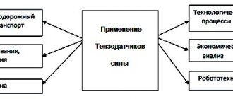
Scope of application of ammeters
Instruments for measuring current have found application in various fields. They are actively used in large enterprises associated with the generation and distribution of electrical and thermal energy.
Where are ammeters used:
electrical engineering - energy
automotive industry
exact sciences
construction
electrical laboratories
But not only medium and large enterprises use this device: they are also in demand among ordinary people. Almost any experienced auto electrician has a similar device in his arsenal, which allows him to measure the power consumption of devices, car components, etc.
Shunt design and connection
To connect the ammeter, use a standard shunt, which is a copper plate mounted on a carbolite insulator. There are two screws on each side of the copper plate: potential and current clamps. The kit includes factory products that have a set resistance and are designed for a certain current.
analog ammeter
To correctly include the shunt in the measurement circuit, adhere to the following algorithm:
- You should choose a product with large expected values. For example, if the estimated current strength in the line being tested is 12–15 A, a product is selected that allows measurements to be taken up to 20 A;
- Next, the measuring wires from the ammeter are connected to the potential terminals on the copper strip;
- The measured line is de-energized;
- Then disconnect the power wires from the device on which you want to check the consumption value;
- The shunt is connected to a break in the electrical line: the disconnected wires are connected to the current clamps.
Now the power is turned on and readings are taken from the ammeter. After this, the line is de-energized again, the measuring device is turned off, and the connections are restored.
Note! The readings obtained are multiplied by the coefficient indicated on the shunt insulation plate. If this coefficient is not specified, you can independently calculate the price of the device division. To do this, the maximum scale value is multiplied by the calculated indicators of the additional plate.
Types of ammeters
Based on the type of reading device, ammeters are divided into devices with:
- with pointer indicator
- with light indicator;
- with a writing device;
- electronic devices.
According to the principle of operation, ammeters are divided
- Electromagnetic – designed for use in direct and alternating current circuits. Typically used in conventional AC electrical installations with a frequency of 50 Hz.
- Magnetoelectric - designed to record the current strength of low values of direct current. They have a magnetoelectric measuring device and a scale with graduated divisions.
- Thermoelectric The devices are designed to measure current in high-frequency circuits. Such devices include a magnetoelectric mechanism made in the form of a conductor to which a thermocouple is welded.
Vasiliev Dmitry PetrovichProfessor of Electrical Engineering, St. Petersburg State Polytechnic University
Ask a Question
The current flowing through the wiring causes it to heat up, which is detected by a thermocouple. The resulting radiation causes the frame to deflect by an angle that is proportional to the current strength.
- Ferrodynamic devices - consist of a closed magnetic circuit made of ferromagnetic material, a core and a fixed coil. They are characterized by high measurement accuracy, reliable design and low sensitivity to the effects of electromagnetic fields.
- Electrodynamic devices are designed for measuring current in DC/AC circuits of high frequencies (up to 200 Hz). They are sensitive to overloads and external electromagnetic fields. But due to the high accuracy of measurements, they are used as control devices for checking existing ammeters.
- Digital ammeters are a modern model of devices that combine the advantages of analog instruments. Today, such devices have gained leading positions. This is due to ease of use, ease of use, small size and high accuracy of the measurement results obtained.
Abrahamyan Evgeniy Pavlovich
Associate Professor, Department of Electrical Engineering, St. Petersburg State Polytechnic University
Ask a Question
In addition, digital devices can be used in a variety of conditions: it is not afraid of shaking, vibration, etc.
Let's look at several ammeters from different manufacturers and different types:
Ammeters Am-2 DigiTOP
Specifications:
- Number of inputs 1
- Measured alternating current 1...50 A
- Measurement error 1%
- Indication resolution 0.1 A
- supply voltage -100…-400 V, 50 (+1) Hz Overall dimensions 90x51x64 mm
Orlov Anatoly Vladimirovich
Head of the Relay Protection and Automation Service of Novgorod Electric Networks
Ask a Question
The performance and durability of household electrical appliances depend on the quality of the electricity received. As a rule, failure of electronic equipment, be it refrigerators, televisions or washing machines, is caused by an increase in voltage above permissible limits. The most dangerous thing is a prolonged increase in voltage above the permissible level. In this case, power supplies for electronic equipment fail, the windings of electric motors overheat, and fire often occurs.
Laboratory ammeter E537
This device (ammeter E537) is intended for accurate measurement of current in AC and DC circuits.
Accuracy class 0.5.
Measuring ranges 0.5 / 1 A;
Weight 1.2 kg.
Technical characteristics of ammeter E537
- Measuring range end value 0.5 A/1 A
- Accuracy class 0.5
- Normal frequency range (Hz) 45 - 100 Hz
- Operating frequency range (Hz) 100 - 1500 Hz
- Overall dimensions 140 x 195 x 105 mm
Ammeter CA3020
The basic model digital ammeter device is available in several standard modifications depending on the basic value of the measured current parameters. When ordering this model of digital ammeter, you must state what basic current parameter you will have to work with: 1 A, 2 A or 5 A.
Basic parameters of the measured current, In-1 Ampere (CA3020-1), 2 Ampere (CA3020-2) or 5 Ampere (CA3020-5);
- The limits of measured currents are from 0.01 In to 1.5 In;
- Frequency range for measured currents from 45 to 850 Hertz;
- The limits of the basic permissible existing error are ±0.2% of the optimal value of the parameters of the measured current strength;
- Power supply voltage - alternating current network with voltage (85-260) Volts and frequency (47-65) Hertz or constant voltage (120 - 300) Volts;
- The power consumption of the device is no more than 4 VA;
- Dimensions 144x72x190 mm;
- Weight no more than 0.55 kg;
- The power consumed by the measuring circuit of series 3020 ammeters does not exceed: for CA3020-1 – 0.12 VA; for CA3020-2 – 0.25 VA; for CA3020-5 – 0.6 VA.
Calculation features
If there are no standard shunts with factory designations, these values can be calculated independently if you use industrial resistors instead of resistance. In this case, proceed as follows:
- To expand the range of the measurement scale, a resistor is connected in parallel to the device, through which the main part of the current passes. In this case, a small part passes through the measuring device, sufficient for measurements;
- The next step is to determine the maximum current value. To do this, a voltmeter, observing polarity, measures the voltage at the power source. The total resistance of the circuit is also determined, by which the voltage value is divided;
- Now you need to find out the resistance of the ammeter winding. This value is indicated in the passport for the device or measured independently;
- It remains to calculate the required resistance of the resistor used as a shunt. To do this, the maximum current is multiplied by the total line resistance, and the resulting value is divided by the rated voltage of the power source.
Now you know not only how, but also how to properly connect it to an electrical circuit. We hope that this material helped you get out of the situation where the measuring scale of the device is not enough for accurate measurements. We figured out that for this you need to connect a standard shunt or calculate it yourself. To determine the current value in an electrical circuit, special devices are used - ammeters.
It might be interesting➡ How to connect an ammeter to an AC or DC circuit
The ammeter is connected in series to the circuit under study, and, due to its extremely low internal resistance, this measuring device does not make any significant changes to the electrical parameters of the circuit. The instrument scale is graduated in amperes, kiloamperes, milliamperes or microamperes. To extend the measurement range, the ammeter can be connected to the circuit through a transformer or in parallel with the shunt, when only a small fraction passes through the device, and the main current of the circuit flows through the shunt.
Interesting read: what are klystrons.
Ammeter full scale gain
The magnitude of the repulsion force and, consequently, the amplitude of the needle movement depends on the amount of current flowing through the coil. It was previously reported that the scope of any instrument can be expanded. In the case of an ammeter, a device called a shunt is used for this purpose.
This allows it to pass only through the moving coil of the device, a current that it can tolerate. The shunt is formed by a pressure resistance of an ohmic value lower than the reading of the moving coil of the device, which allows the passage of another portion of the current that is not allowed.
Digital ammeter
In order to determine the voltage at the terminals of the energy receiver or generator using the readings of a voltmeter, it is necessary to connect its terminals to the terminals of the voltmeter so that the voltage at the receiver (generator) is equal to the voltage at the voltmeter. The resistance of the voltmeter must be large compared to the resistance of the energy receiver (or generator) so that its inclusion does not affect the measured voltage (the operating mode of the circuit).