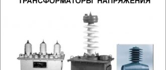
Voltage transformer - designed to reduce the primary voltage to values convenient for measuring instruments and relays, as well as to separate measurement circuits and protection from high voltage primary circuits. Used in AC circuits with a frequency of 50 or 60 Hz with rated voltages from 0.22 to 750 kV.
High voltage transformer (left) and low voltage transformer (right)
Principle of operation
It consists of a steel core composed of electrical steel sheet plates, a primary winding and 1 or 2 secondary windings (the design of a specific device can be found in the manufacturer’s passport or catalog).
As a result of manufacturing, the required accuracy class must be achieved in terms of:
- amplitude,
- corner.
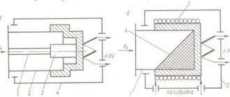
The operating principle of a voltage measuring transformer is no different from a power step-down transformer or a current transformer.
Let us once again describe the operation of the current transformer. An alternating current passes through the primary winding; this current forms a magnetic flux that penetrates the magnetic circuit and the HV and LV windings. If a load is connected to the secondary winding, a current will begin to flow through it, which arises due to the action of EMF (electromotive force). EMF is induced due to the action of magnetic flux. By selecting different numbers of turns of the primary and secondary windings, you can obtain the desired output voltage.
Transformer operating principle
Such devices operate only on alternating voltage. If a constant voltage is applied to the VT, because EMF will not be created by a constant magnetic flux.
A little more about the specifics of some species ↑
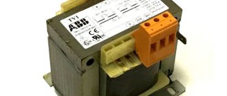
The types of transformer voltage directly affect the type of device used. If we are talking about voltages up to 6 kV, then dry type transformers are used, in other cases it is necessary to use oil models.
Internal transforming devices can operate in the range from -40 to + 45 degrees with air humidity of no more than 80 percent. Single-phase internal transformers have cast insulation and differ from oil-based analogues in their lighter weight, more modest size and ease of operation.
Features and differences between oil and dry transformers ↑
Let us remind you that oil transformers are insulated and cooled using an oil composition.
The structure of an oil transformer is a magnetic circuit combined with windings, a tank and a cover. The main element - the magnetic circuit - is assembled from separate steel sheets, well insulated to avoid losses.
The material for the windings is bare wire, usually made of copper or aluminum of various sections. To regulate the voltage, the existing winding is supplemented with branches connected to a toggle switch or switch.
Each transformer of this type has two main types of switching: they can be adjusted under load while the device is connected, and also without load when it is disconnected. The second method is considered the most popular - it is much simpler and safer.
Oil transformers can also be produced sealed. In this case, the oil itself does not come into contact with the air, which means it oxidizes more slowly and gains moisture. Devices of this type are completely filled with a special oil liquid and therefore do not have an expansion tank. As for compensation for expansion due to heating and contraction when temperature decreases, this function is performed by the corrugations of the walls of the tank itself. Another advantage is their improved insulation, since oil filling occurs under vacuum.
The second type is dry transformers, in which air plays the role of cooling. They also represent a connection of a magnetic core and two or three windings, which are placed in a protective compartment. Since air is a much less ideal cooling medium than viscous oil, in such devices the insulation gaps, as well as the channels intended for ventilation, are made larger.
The insulation in the dry version is glass material of high heat resistance class and silicone varnishes that prevent the winding from interacting with moisture. By the way, this makes them much more fireproof than the oil version. These installations can be safely used in any premises, including residential premises.
Where dry-type transformers really fall short is in size. They are more bulky and also have less ability to withstand overloads.
Engineering has all the necessary tools for high-quality maintenance of transformer substations, a well-coordinated team of professionals and licenses that give the right to carry out all the necessary tests and measurements. By choosing the ProfEnergia electrical laboratory, you are choosing reliable and high-quality operation of your equipment!
If you want to order service for transformer substations or ask a question, call: +7 (495) 181-50-34.
Diversity and specialization ↑
Of course, devices of each type and type are used strictly for their intended purpose or within the existing tolerances. Any use of transformers in conditions not intended for their operation is fraught not only with damage to the device itself, but also with very sad consequences for the entire circuit. In order to avoid the possible consequences of incorrect and inappropriate use of transformers, you should carefully read the product data sheet or instructions, as well as existing GOST standards.
Decoding TN
Explanation of markings:
- N - voltage transformer;
- T - three-phase;
- O - single-phase;
- C - dry;
- M - oil;
- K - cascade or with correction;
- A - anti-resonance;
- F - in a porcelain case;
- I — Isolation control;
- L - in a molded epoxy body;
- DE - with a capacitive voltage divider;
- Z - with a grounded primary winding.
Also read: Three-phase power transformer - TMG
Transformation ratio
Transformation ratio - shows how many times the primary voltage value increases or decreases.
Formula for calculating the transformation ratio
Secondary voltage
Voltage on the secondary winding:
- 100 V,
- 100/√3 V,
- 100/3.
Accuracy classes
Accuracy classes:
- 0,1;
- 0,2;
- 0.5 – used for measurements;
- 1,0;
- 3,0;
- 3P or 6P – designed for protection, control, automation or alarm.
The rated power of transformers for any accuracy class should be selected from the range (VA): 10; 15; 25; thirty; 50; 75; 100; 150; 200; 300; 400; 500; 600; 800; 1000; 1200.
Classification of voltage transformers
TNs are classified according to the following parameters:
- primary winding voltage (3, 6, 10 ... 750 kV)
- voltage of the main secondary winding (100 V - for single-phase, connected between phases, three-phase; 100√3 - single-phase, connected between phase and ground voltage of the additional secondary winding (100V - single-phase in a network with a grounded neutral, 100√3 - single-phase in a network with isolated neutral
- number of phases (single-phase, three-phase)
- number of windings (two-winding, three-winding)
- accuracy class (0.1 0.2 0.5 1 3 3Р 6Р)
- cooling method (dry, oil, gas-filled)
- insulation (air-paper, cast, compound, gas, oil, porcelain)
For voltages of 6 and 10 kV, cast transformer transformers filled with epoxy resin are used. These devices are installed in switchgears. They take up smaller dimensions compared to oil ones. Their advantages also include less maintenance.
Types and classifications
Main classifications of transformers:
- By number of phases.
- Based on the presence or absence of grounding of the output,
- According to the principle of action.
- According to the number of stages of transformation.
- By the presence of a compensation winding or a winding for monitoring network insulation.
- By type of insulation:
- According to design features.
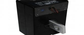
Old 3-phase oil transformer
Installation location:
- outdoor,
- internal,
- built into the power transformer,
- installation as a separate element.
The main features of transformers and their designations are given in the table:
A three-winding transformer should be made with two secondary windings:
- basic,
- additional.
Purpose and principle of operation
A voltage transformer converts the operating potential using the principle of electromagnetic induction.
The main purpose of voltage transformers is to convert the input signal to the level required by the user's tasks - when the operating potential needs to be lowered or increased. This can be achieved through the principle of electromagnetic induction, formulated as a law by scientists Faraday and Maxwell. According to it, in any loop located close to another similar turn of wire, an EMF is induced with current, proportional to the flux of magnetic induction penetrating them. The magnitude of this induction in the secondary winding of the transformer (consisting of many such turns) depends on the current strength in the primary circuit and on the number of turns in both coils.
The current in the secondary winding of the transformer and the voltage on the load connected to it are determined only by the ratio of the number of turns in both coils. The law of electromagnetic induction allows you to correctly calculate the parameters of a device that transmits power from input to output with the desired ratio of effective currents and voltages.
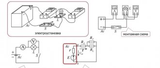
Connection diagrams
Connection diagrams for single-phase voltage transformers:
Connection diagrams for three-phase voltage transformers:
Diagrams and groups of connections of windings of three-phase three-winding transformers with main and additional secondary windings
Also read: Single-phase reference current transformer - TOP
Special types of transformers
This group includes:
- dividing
- coordinating
- high frequency
- welding and other types of transformer devices designed to perform special electrical tasks
Isolation transformers
Placing two windings of exactly the same design on a common magnetic circuit allows us to obtain the same output voltage from 220 volts 50 hertz at the input.
This begs the question: why make such a transformation? The answer is simple: to ensure electrical safety.
Fire and explosion safety of the device
The explosion safety of the devices is ensured by the design features. The manufacturer indicates the security class in the annotation for the device. Fire ratings may also vary. Modern closed boxes for storing engineering equipment help protect workers and ordinary citizens from injury.
The device must be located indoors and access to it by unauthorized persons is prohibited.