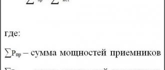
Voltage converters are widely used both in everyday life and in production. For production and industry, they are most often made to order, because they need a powerful converter and not always with a standard voltage. Standard values for output and input parameters are often used in everyday life. That is, a voltage converter is an electronic device that is designed to change the type of electricity, its magnitude or frequency.
According to their functionality they are divided into:
- Downgrades;
- Raising;
- Transformerless;
- Inverter;
- Adjustable with adjustable frequency and output AC voltage;
- Adjustable with adjustable constant output voltage.
Some of them can be made in a special sealed design; these types of devices are used for wet rooms, or, in general, for installation under water.
So, what is each type?
High voltage voltage converter
This is an electronic device that is designed to produce alternating or direct high voltage (up to several thousand volts).
For example, such devices are used to generate high-voltage energy for television picture tubes, as well as for laboratory research and testing electrical equipment with voltages increased several times. Cables or power circuits of oil switches designed for a voltage of 6 kV are tested at a voltage of 30 kV and higher, however, this voltage value does not have high power, and in the event of a breakdown it is immediately switched off. These converters are quite compact because they have to be carried by personnel from one substation to another, most often manually. It should be noted that all laboratory power supplies and converters have almost standard, accurate voltage. Simpler high-voltage converters are used to start fluorescent lamps. The impulse can be greatly increased to the desired level using the starter and throttle, which can have an electronic or electromechanical basis.
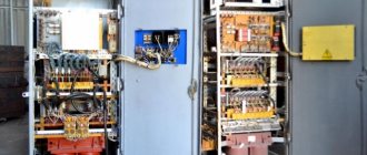
Industrial installations that convert lower voltage to high voltage have many protections and are performed using step-up transformers (STVs). Here is one of these circuits that gives an output from 8 to 16 thousand volts, while only about 50 V is needed for its operation.
Due to the fact that quite high voltage is generated and flows in the windings of transformers, high demands are placed on the insulation of these windings, as well as on its quality. In order to eliminate the possibility of corona discharges, the parts of the high-voltage rectifier must be soldered to the board carefully, without burrs and sharp corners, and then filled on both sides with epoxy resin or a layer of paraffin 2...3 mm thick, ensuring insulation from each other. Sometimes these electronic systems and devices are called step-up voltage converters.
The following circuit is a linear resonant voltage converter that operates in boost mode. It is based on the separation of functions for increasing U and its clear stabilization in completely different cascades.
At the same time, some inverter units can be made to work with minimal losses on power switches, as well as on a rectified bridge, where high-voltage voltage appears.
Operating principle of pulse converters
Today, there are many pulsed-DC voltage converters, differing in the number and type of reactive components, conversion algorithms and other characteristics. However, the simplest, and therefore the most popular, are only four circuits: buck, boost, inverting and flyback (Figure 2). These converters use the same operating principle, have an identical number of components and differ only in the method of switching the storage choke L1, on the operating mode of which all the characteristics of the circuit depend.
Rice. 2. Circuits of the most popular converters
The conversion of electrical energy occurs in two stages. At the first stage, the switch S1 is closed, and a certain voltage VL1 is applied to the inductor L1, under the influence of which, during the time tON, its current increases by the amount dI1 (formula 2, Figure 3):
$$dI_{1}=\frac{V_{L1}}{L_{1}}\times t_{ON},\qquad{\mathrm{(}}{2}{\mathrm{)}}$$
where L1 is the inductance of the winding active in the first stage.
In this case, a voltage of reverse polarity is applied to the diode VD1, so no current flows through it. At the end of this interval, the inductor current reaches the maximum value IMAX1, which means that energy E accumulates in its magnetic circuit (formula 3):
$$E=\frac{I_{MAX1}^2\times L_{1}}{2}\qquad{\mathrm{(}}{3}{\mathrm{)}}$$
Rice. 3. Diagrams of inductor voltage and current of various converters
Since at the first stage the energy in the choke increases, it is often called the stage of accumulation or charging of the choke.
After opening the switch S1, a self-induction EMF is formed at the terminals of all windings of the inductor, the polarity of which is opposite to the polarity present at the first stage, this means that the inductor L1 now becomes not a consumer, but a source of electrical energy. Changing the polarity of the voltage on the windings leads to the opening of the diode VD1, which provides the path for current flow in the second stage, called the return stage, or inductor discharge.
Since the amount of energy in the inductor at the moment of switching the keys does not change, the current in its active winding immediately after opening the key S1 will also be maximum, but its value IMAX2 may change, because it can now flow through a different number of turns (formula 4):
$$E=\frac{I_{MAX2}^2\times L_{2}}{2},\qquad{\mathrm{(}}{4}{\mathrm{)}}$$
where L2 is the inductance of the winding active in the second stage.
The buck, boost and inverter choke usually contains only one winding, so L1 = L2, and therefore IMAX1 = IMAX2 = IMAX. But for a flyback circuit, the inductances L1 and L2 most often differ, so the current IMAX2 can be determined (formula 5) by equating formulas 3 and 4:
$$I_{MAX2}=I_{MAX1}\times \sqrt{\frac{L_{1}}{L_{2}}}=I_{MAX1}\times \frac{N_{1}}{N_{2 }},\qquad{\mathrm{(}}{5}{\mathrm{)}}$$
where N1 and N2 are the number of turns, respectively, of the primary and secondary windings.
The second part of formula 5 can be easily obtained by remembering that the inductance of the winding is proportional to the square of the number of turns (formula 6):
$$L_{1,2}=N_{1,2}^2\times A_{L},\qquad{\mathrm{(}}{6}{\mathrm{)}}$$
where AL is the design parameter of the magnetic circuit.
After the diode opens, the voltage on the inductor winding is fixed at the level VL2, under the influence of which the inductor current during the time tOFF will decrease by the amount dI2 (formula 7):
$$dI_{2}=\frac{V_{L2}}{L_{2}}\times t_{OFF}\qquad{\mathrm{(}}{7}{\mathrm{)}}$$
In a quasi-steady state, when there are no transient processes in both the power and load circuits, the inductor at the second stage of conversion must release all the energy accumulated in the first interval. This means that by the time the next cycle begins, its current should be the same as at the beginning of the previous one. For circuits with a single-winding inductor dI1 = -dI2, but in the general case (for a flyback converter), changes in winding currents are determined by the Total Current Law (formula 8):
$$dI_{1}\times N_{1}=-dI_{2}\times N_{2}\qquad{\mathrm{(}}{8}{\mathrm{)}}$$
Substituting ratios 2 and 7 into formula 8, taking into account 6, we can obtain the basic equation 9, which relates the voltage values at the terminals of the inductor windings with the ratio of the durations of the main stages of the conversion:
$$\frac{V_{L1}}{N_{1}}\times t_{ON}=-\frac{V_{L2}}{N_{2}}\times t_{OFF}\qquad{\mathrm{ (}}{9}{\mathrm{)}}$$
Formula 9 is the basis for obtaining the regulating characteristics of the converter - the dependence of the output voltage on the relative duration of the first stage of conversion D = tON/(tON + tOFF). However, in order to obtain these dependencies, it is further necessary to consider each scheme separately.
Home voltage converter
Voltage converters
The average person comes across voltage converters for the home very often, because many devices have a power supply. Most often these are step-down converters that have galvanic isolation. For example, chargers for mobile phones and laptops, personal desktop computers, radios, stereo systems, various media players, and this list can be continued for a very long time, since their variety and applications in everyday life have recently been very wide.
Uninterruptible power supplies are equipped with energy storage devices in the form of batteries. Such devices are also used to maintain the operation of the heating system during an unexpected power outage. Sometimes home converters can be made according to an inverter circuit, that is, by connecting it to a direct current source (battery) powered by a chemical reaction, you can obtain a normal alternating voltage at the output, the value of which will be 220 Volts. A feature of these circuits is the ability to obtain a pure sinusoidal signal at the output.
One of the very important characteristics of converters used in everyday life is the stable signal value at the output of the device, regardless of how many volts are supplied to its input. This functional feature of power supplies is due to the fact that for stable and long-term operation of microcircuits and other semiconductor devices, a clearly standardized voltage is required, and even without ripple.
The main criteria for choosing a converter for a house or apartment are:
- Power;
- The magnitude of the input and output voltage;
- Possibility of stabilization and its limits;
- Load current value;
- Minimizing heating, that is, it is better for the converter to operate in a mode with a power reserve;
- Ventilation of the device can be natural or forced;
- Good sound insulation;
- Availability of protection against overloads and overheating.
Choosing a voltage converter is not a simple matter, because the operation of the powered device depends on the correctly selected converter.
Features of application
At the moment, such equipment is used in almost all industries and every day it is increasingly used in the life of every person, in particular as part of the equipment of cars or trucks. The operating frequency of voltage inverters (voltage converters) does not exceed one hundred kilohertz. Plus, a voltage converter (voltage inverter) can be used as a generator. In principle, a generator and an inverter are quite similar, but you should not assume that these types of equipment are the same in purpose and operating principle.
Boost converter.
There are significant differences in the generator and voltage converter circuits. In addition, compared to a diesel or gasoline generator, a voltage inverter (voltage converter) has a number of advantages, in particular:
- the voltage inverter (voltage converter) has significantly smaller dimensions and weight;
- The voltage inverter (voltage converter) does not need to constantly monitor a whole list of parameters that are mandatory when operating diesel power plants or gasoline generators. These parameters include fuel level, engine oil level and pressure, coolant temperature and level. All these parameters, for example, when operating a voltage inverter (voltage converter) from a car engine are controlled independently, in addition, with relatively low-power consumers (say, up to 1000 W), turning on the car generator for a long time is not required at all and, naturally, no fuel is consumed;
- at idle, the voltage inverter (voltage converter) has a meager energy consumption (about 5 W), in contrast to a diesel or gasoline generator, which at idle consumes up to fifty percent of the consumption at maximum load;
- absence of mechanical wear, respectively, better fault tolerance and longer service life;
- the fluctuation in the output frequency of the voltage inverter (voltage converter) is minimal and, as a rule, does not exceed hundredths of a percent;
- the voltage inverter (voltage converter) is environmentally friendly (does not make noise and does not emit exhaust gases) and allows you to connect alternative energy sources (for example, solar panels or wind generators);
- a voltage inverter (voltage converter) can be used as a starter-charger, as an uninterruptible power supply, as a battery restorer;
- and, finally, a voltage inverter (voltage converter) is simply significantly (up to several times!) cheaper.
Table - Popular models of voltage converters.
The list of potential users of voltage inverters (voltage converters) can be very wide. Here are producers of various works in remote conditions or with frequent power outages, and lovers of outdoor recreation who want to preserve the opportunity to enjoy the “benefits of civilization”, and prudent owners of various industries or protected objects, etc. and so on.
Material on the topic: Principles of operation of a multimeter and features of choice.
In particular, the use of voltage inverters (voltage converters) in conjunction with various autonomous power sources provides very big advantages; the fuel savings alone are worth it, and there is also a stored “reserve of electricity”, so to speak, just in case.
It will be interesting➡ Why do you need a frequency converter
True, when choosing voltage inverters (voltage converters), it is necessary to remember that many consumers of electric current (especially refrigerators and pumps) have a starting power several times higher than the rated power (usually, you can look at the device’s passport) and it is this that should be taken as a basis when calculating the required voltage inverter (voltage converter).
Converter 24V to 12V
Transformerless voltage converters
Features of a voltage converter from 12V to 220V
Recently, they have become very popular, since their production, and in particular the production of transformers, requires a lot of money, because their winding is made of non-ferrous metal, the price of which is constantly growing. The main advantage of such converters is, of course, the price. Among the negative aspects, there is one thing that significantly distinguishes it from transformer power supplies and converters. As a result of a breakdown of one or more semiconductor devices, all the output energy can reach the terminals of the consumer, and this will certainly damage it. Here is the simplest AC to DC voltage converter. The role of the regulating element is played by the thyristor.
The situation is simpler with converters that do not have transformers, but operate on the basis and in the mode of a voltage-increasing device. Here, even if one or several elements fail, dangerous destructive energy will not appear on the load.
Features of nanoPower converters
As can be seen from the operating principle, the maximum efficiency value of pulse converters is theoretically unlimited. But in practice there will always be losses due to the imperfection of the element base, so the real value of the power unit efficiency of the best representatives of pulse converters is at the level of 98...99%.
However, when calculating the efficiency of the converter as a whole, the energy costs for operating the control circuit should also be taken into account. If we look at the block diagrams of controllers that implement the two most popular control methods today - voltage (Figure 9) and current (Figure 10) - you can see that a fairly large number of nodes is required to provide an output voltage of the required quality. And although today the manufacturing technology of semiconductor microcircuits is at a very high level, nevertheless, when the power of the power part of the converter is negligible, the current consumption of control nodes can be commensurate with the current of the loads.
Rice. 9. Converter controller with voltage control method
Rice. 10. Converter controller with current control method
For DC-DC converter controllers, there are three main currents that you should pay attention to when choosing: the current consumed from the input IQINT, the output IQOUT circuit in the active mode, and the leakage current ISDT consumed by the microcircuit in the off state (Figure 11). These currents, if possible, should be minimal, because the lower they are, the higher the efficiency of the converter.
Rice. 11. Current paths IQINT, IQOUT and ISDT of the MAX17222 chip
Of these parameters, the most important for battery-powered devices is the leakage current ISDT. And this is due to the specifics of their work, because as practice shows, most of the time they are either asleep (on duty) or in a switched off state. Since it is not possible to physically disconnect the converter control circuit from the power supply in most cases, the ISDT leakage current will directly affect the battery life.
In nanoPower integrated DC-DC converters, the main technology for reducing IQINT, IQOUT and ISDT currents is a thorough study of the circuitry of the internal components of the controller and the manufacturing processes of integrated components. Other methods for reducing your own power consumption include turning off the resistive output voltage divider used in the feedback circuit. All this made it possible to achieve impressive values for the self-power consumption of these nodes. For example, for MAX17220/21//// boost converter chips, the current consumed from the load circuits (IQOUT) does not exceed 300 nA, and the currents consumed from the power supply (IQINT, ISDT) are only 0.5 nA.
In addition, boost converters have one specific feature that also needs to be paid attention to. When using semiconductor diodes or n-channel MOSFETs as the upper switch, it becomes impossible to completely turn off the output voltage - when the converter stops, there is a supply voltage at its output, which leads to an increase in power consumption. Therefore, nanoPower microcircuits also implement True Shutdown technology, which blocks the appearance of voltage at the output of the converters when they are turned off.
Today, the nanoPower line of low-power converters includes microcircuits for the most popular converter circuits: buck and boost types (Table 2). The MAX17220...25 line of boost converters (Figure 12) allows you to provide the load with an output voltage of 1.8...5 V, set by selecting an external resistor RSEL in 0.1 V steps. The input voltage can be in the range of 0.4...5.5 IN.
The high degree of integration made it possible to use miniature six-pin WLP and µDFN packages for the MAX17220...25 chips and use a minimum number of external components. As can be seen from Figure 12, in addition to the required external reactive elements - capacitors CIN, COUT and storage choke, which, firstly, are technologically difficult to manufacture in an integrated design, and secondly, their parameters depend on the specific application, the operation of the microcircuits requires only one external precision (with an accuracy of 1%) resistor RSEL, which is responsible for the output voltage.
Table 2. Characteristics of nanoPower chips
| Name | Current consumed from the output circuits IQOUT, nA | Current consumption in off state ISDT, nA | Maximum current of the storage choke, mA | Output current, mA | Frame | Development board |
| MAX38640A | 330 | 5 | 250 | 160 | WLP/6 | MAX38640EVKIT |
| MAX17220 | 300 | 0,5 | 225 | 205 | WLP/6, µDFN/6 | MAX17222EVKIT, MAX17220EVKIT |
| MAX17222 | 300 | 0,5 | 500 | 200 | WLP/6 | MAX17222EVKIT |
| MAX17223 | 300 | 0,5 | 500 | 205 | WLP/6, µDFN/6 | MAX17222EVKIT, MAX17220EVKIT |
| MAX17224 | 300 | 0,5 | 1000 | 205 | WLP/6, µDFN/6 | MAX17222EVKIT, MAX17220EVKIT |
| MAX17225 | 300 | 0,5 | 1000 | 205 | WLP/6, µDFN/6 | MAX17222EVKIT, MAX17220EVKIT |
Rice. 12. Block diagram of MAX17220…25 microcircuits
The MAX17220...25 microcircuits implement a current control method, so the value of the inductance of the storage choke largely determines the operating frequency of the converter. For most applications based on these chips, you can use small-sized chokes in the 0603 package with an inductance of 2.2 μH with a maximum current of 225 mA, 500 mA or 1 A. All this allows for the implementation of ultra-compact boost converters that occupy an area of \u200b\u200bthe printed circuit board not exceeding 6.75 mm2.
The MAX38640/41/42/43 step-down converter chips have similar characteristics (Figure 13), allowing the input voltage of 1.8...5.5 V to be reduced to 0.7...3.3 V (chips with the suffix A) or to 0 .5…5.0 V (with suffix B). Like the boost converters discussed above, the MAX38640...43 uses a single precision RSEL resistor to set the output voltage, and the ICs themselves require only four external components.
Rice. 13. Block diagram of MAX38640…43 microcircuits
To speed up the time to market for products, Maxim Integrated offers developers maximum support that goes beyond providing all necessary technical documentation. For example, on the company’s official website there are mathematical models with which you can study the electrical processes of the circuits being developed in specialized development environments: the offline EE-Sim® OASIS Simulation Tool based on the SIMPLIS® kernel and the online EE-Sim Design And SimulationTool. Both environments are focused on the development of switching power supplies and allow, based on the proposed templates, to assemble a virtual analogue of the circuit being developed in less than 5 minutes.
In addition, to evaluate the real capabilities of nanoPower chips, Maxim Integrated offers specialized development boards. For example, for the MAX17220...25 chips, the MAX17222EVKIT (Figure 14), consisting of two independent parts containing the same MAX17222 chip, but manufactured in different packages: µDFN and WLP. The Maxim Integrated catalogs also contain a similar development board MAX17220EVKIT with installed MAX17220 chips (in two package options) and MAX38640EVKIT with installed MAX38640A in a WLP package.
Rice. 14. Appearance of the MAX17222EVKIT development board
DC-DC converters
Pulse voltage converters
The AC/DC converter is the most commonly used type of device of this type. In everyday life these are all kinds of power supplies, and in production and industry these are power supply devices:
- All semiconductor circuits;
- Excitation windings of synchronous motors and DC motors;
- Oil switch solenoid coils;
- Operating and tripping circuits where coils require constant current.
A thyristor voltage converter is the most commonly used device for these purposes. A feature of these devices is the complete, rather than partial, conversion of alternating voltage to direct voltage without any kind of ripple. A powerful voltage converter of this type must necessarily include radiators and fans for cooling, since all electronic parts can operate for a long time and trouble-free only at operating temperatures.
Additional protection
A modern inverter must have short circuit protection. It installs a safety device against accidental exposure to outside interference, especially when it comes to children.
You might be interested in this Designation and principle of operation of a triac: explanation for dummies
Overload protection must be triggered in a timely manner to prevent overheating of the wiring and subsequent fire. The protection unit protects the converter from short circuits and high input voltage. For this purpose, there are indicators that show the state of the electrical network.
Additional sensors and installed voltmeters will help identify the corresponding malfunction. System temperature indicators located on the cooling radiator will allow you to control the fan when the readings exceed the permissible value.
Adjustable voltage converter
These devices are designed to operate in both voltage increase and decrease modes. Most often, these are still devices that smoothly adjust the value of the output signal, which is lower than the input signal. That is, 220 Volts are supplied to the input, and at the output we get an adjustable constant value, say, from 2 to 30 volts. Such devices with very fine adjustment are used to test pointer and digital instruments in laboratories. It is very convenient when they are equipped with a digital indicator. It must be admitted that every radio amateur took this type as the basis for his first work, since the power supply for certain equipment can be different in size, but this power source turned out to be very universal. How to make a high-quality converter that works for a long time is the main problem of young radio amateurs.
Selection criteria and calculation of a voltage inverter
The most important characteristics of the inverter:
- voltage converter frequency and voltage shape. It is advisable to purchase a device that produces a pure sinusoidal signal. Even highly sensitive equipment can be connected to such a converter;
- rated power. It must be higher than the total load of all connected consumers;
- maximum peak power. This value determines the maximum load the device will withstand when connecting equipment with a low cos f value. Such equipment includes electric motors, pumps, compressors;
- value of input/output voltage and electric current.
To calculate the required power of a DC/AC converter, you must:
- Add up the power consumed by the connected equipment. It is taken from the passport data for the equipment. For example, a refrigerator - 200 W, a washing machine - 1500 W, a vacuum cleaner - 1000 W. Total in total: 200 + 1500 + 1000 = 2700 W.
- Consider peak load. To do this, we multiply the resulting amount by a factor of 1.3 (for the example under consideration: 2700 * 1.3 = 3510 W).
- Take into account the coefficient cos f to obtain the result in volt-amperes. Its value for different equipment varies within 0.60...0.99. For calculation it is better to take the minimum value. 3510/0.6 = 5850 VA ≈ 6 kVA. It is this value that you should focus on when choosing an inverter.
Inverter voltage converter
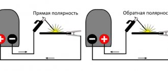
This type of converter forms the basis for innovative compact welding devices. Receiving an alternating voltage of 220 volts for power supply, the device rectifies it, after which it again makes it alternating, but with a frequency of several tens of thousands of Hz. This makes it possible to significantly reduce the dimensions of the welding transformer installed at the output.
The inverter method is also used to power heating boilers from batteries in the event of an unexpected power outage. Due to this, the system continues to operate and receives 220 volts of alternating voltage from 12 volts of direct voltage. A powerful booster device for this purpose must be operated from a large-capacity battery; this determines how long it will supply the boiler with electricity. That is, capacity plays a key role.
Converter with the latest parts
A homemade inverter can operate in a stable mode if the transistor at the outputs operates from an amplified source with the main generator. For this purpose, it is allowed to use elements of the KT819GM series installed on dimensional radiators.
When creating converters, a simplified scheme is used. As the process progresses, you should take care of purchasing the necessary materials:
- microcircuits KR121EU1;
- transistors IRL2505;
- soldering iron;
- tin.
KR12116U1 microcircuits have a remarkable property: they contain a pair of channels for regulating the switch and allow you to quite simply make a simple voltage converter. Microcircuits in the temperature range from +25 to +30°C produce a maximum voltage value within the range of 3 and 9 V.
The frequency of the master oscillators is determined by the parameter of the element in the circuits. The IRL2505 transistor is installed when used on the outputs. It must receive a signal with the proper level, due to which the output transistor is adjusted.
The formed low levels do not allow the transistor to transition from closed modes to any other states. As a result, the occurrence of instantaneous current flows during simultaneous opening of the keys is completely eliminated. If high levels are observed to reach the first output, then this helps to turn off pulse generation. The circuit determines the connection of the common wire to pin 1.
To install push-pull cascades, T1 transformers and two transistors are used: VT1 and VT2. In open channels you can see a resistance value of 0.008 Ohm. It is insignificant, and therefore the power value of the transistor is small, even if a large current passes. Output transformers with a power of 100 W allow the IRL2505 to apply a current of 104 A, and pulse transformers are 360 A.
The main features of inverters include the ability to use any transformer that has two 12 V windings at its outputs.
If the output power is about 200 W, then in such cases the transistor is not installed on the radiator. It is important to consider that the value of electric current with a power of 400 W reaches about 40 A.
Recommendations for the selection of radio elements for a 12–220 V voltage converter
The CD-4047 board is not designed for high-precision control of field-effect transistors, but it copes with this task perfectly. Also, for the device to operate, you will need a transformer from an old 250 or 300 W UPS with a primary winding and a middle positive connection point from the power source.
The transformer has a fairly large number of secondary windings. You will need to use a voltmeter to measure all the taps and find the 220V network winding. The necessary wires will produce the highest electrical resistance of approximately 17 Ohms; you can remove the excess wires.
Before you start soldering, it is advisable to double-check everything. It is recommended to select transistors from the same batch and with the same characteristics. They can be determined with a special tester. Since the CD-4047 board has no analogues, it is necessary to purchase it, but the field-effect transistors can, if necessary, be replaced with n-channel ones with a voltage of 60V or more and a current of at least 35A. Suitable from the IRFZ series. The circuit can also operate using bipolar transistors at the output, but it should be noted that the power of the device will be much less when compared with a circuit that uses “field switches”.
Limiting gate resistors should have a resistance of 10-100 ohms, but it is preferable to use resistors of 22-47 ohms, which have a power of 250 mW.
Often the driving circuit is assembled exclusively from the elements indicated in the diagram, which has precise settings at 50 Hz.
High frequency voltage converter
Due to the use of boost converters, it becomes possible to reduce the size of all electronic and electromagnetic elements that make up the circuits, which means the cost of transformers, coils, capacitors, etc. is reduced. However, this can cause high-frequency radio interference, which affects the operation of other electronic devices. systems, and even ordinary radio receivers, so their housings need to be reliably shielded. The calculation of the converter and its interference must be carried out by highly qualified personnel.
What is a resistance to voltage converter? This is a special type that is used only in the production and manufacture of measuring instruments, in particular ohmmeters. After all, the basis of an ohmmeter, that is, a device that measures resistance, is made in measuring the drop in U and converting it into pointer or digital indicators. Typically measurements are made relative to direct current. A measuring transducer is a technical device used to convert a measured value into another value or a measuring signal, convenient for processing, storage, further transformations, indication, and transmission. It is part of any measuring device.
Well, a very simple 12V/220V inverter
Dmitrij 10-02-2018, 13:05 180 824 Electronics Added 20 comments Often in life there is a need to obtain a voltage of 220V from a lower voltage, say, 12 Volts.
For example, you need to connect a laptop charger to a car battery; with an inverter this is not a problem. In addition, inverters have found wide application in alternative energy.
They are usually installed on wind turbines, hydroelectric power stations, etc., which in most cases generate low voltage.
Today we will look at how to make an inverter with your own hands.
There are no complex electronics here, the set of components is very small, and the circuit is understandable to any beginner. All you need is to connect several resistors, transistors and a transformer. Intrigued? Then let's move on to studying the instructions!
Materials and tools used by the author:
List of materials:
- transformer 12-0-12V 5A; - 12V battery; - two aluminum radiators; - two TIP3055 transistors; - two 100 Ohm/10 Watt resistors; - two 15 Ohm/10 Watt resistors; - wires; - plywood, laminate (or other things for making a case); - socket; - thermal paste; - plastic ties; - screws with nuts, etc.
List of tools:
– soldering iron;
– drill;
- glue gun; - wire cutters; - screwdriver.
Inverter manufacturing process:
Step one. Check out the diagram
Check out the connection diagram for all elements. There is both a detailed electronic diagram and a simple, intuitive diagram of where and what wires to connect.
Step two. We assemble two circuits from resistors and transistors
We take the transistor and attach it to a 15 Ohm resistor, as seen in the photo. We attach the second transistor in the same way.
Step three. Radiator
During operation, transistors will heat up, and if this heat is not removed, they may fail. Here you will need two radiators. We drill holes, apply thermal paste and firmly tighten the transistors to the radiators with self-tapping screws.
Step four. We connect two circuits using 100 Ohm resistors
We take two 100 Ohm resistors and connect the two circuits diagonally. That is, you need to solder the contacts to the two leftmost legs of the transistors, if you look at their front part.
Step five. Connecting the central legs
We take a two-wire cable and solder one wire at a time to the central contacts of the transistors. These wires are then soldered to the leftmost and rightmost pins on the transformer, as can be seen in the photo.
Step six. Jumper
According to the diagram, you need to install a jumper between the outermost and rightmost contacts of the transistors. We cut off a piece of wire and solder them to the paws.
Step seven. Further connection
We take another piece of wire, the author has it pink. Solder it to the central contact of the transformer, through it the positive from the battery will be supplied to the transformer. You will also need a piece of white wire, this will be the negative from the battery, it needs to be soldered to the yellow wire, that is, the jumper installed earlier.
Step eight. Let's test!
Before you know it, the electronic part of the inverter has been assembled and you can test it! We connect the battery and measure the voltage with a multimeter. It jumps in the range of 200-500V. First, the author decided to connect a very weak 5-watt light bulb to the inverter; it lit up without any problems.
Then a more serious 40-watt light bulb was connected, and it lights up as if it were plugged into an outlet at home, but in fact it is powered by a small 12V battery.
Finally, the author decided to connect a 15W fluorescent lamp, it also lit up without any problems.
We also decided to try connecting a mobile phone charger. The phone charges without any complaints.
Step nine. Assembling the body
To make everything safe and look aesthetically pleasing, we will make a housing for the inverter! To do this, you will need a socket, a piece of cable, and plywood, laminate or something similar. We cut the material into the required pieces to make a box. We screw the transformer to the base; for reliability, the author decided to fasten it with screws and nuts. As for the electronic part with transistors, it was decided to secure it with plastic ties. We drill holes and attach the lower 100 ohm resistors to the base.
The body can be assembled; for this purpose the author used hot glue. As for the top cover, you need to cut out a seat for the socket in it. The author's material is soft; he cuts out the window using a stationery knife. If the window is the right size, the socket should lock securely. On the reverse side it can be further strengthened with hot glue or epoxy. It's time to install the cover; we attach it with self-tapping screws in order to have access to the insides of the inverter.
Step ten. Final tests
The inverter is ready, you can check it! Light bulbs burn without difficulty, but what will happen to more serious electronics? The author tries to power a network router from his brainchild and it works without problems! Now you will not be left without WI-FI, even if the lights are turned off.
Do-it-yourself installation of a 12–220 V voltage converter
We install all the elements in the case of the computer power supply; the transistors should be installed on separate radiators.
If a common heat sink is installed, be sure to isolate the transistor housing from the heatsink. We connect the cooler to a 12V bus.
One of the significant disadvantages of this inverter is the lack of short circuit protection. If a short circuit occurs, all transistors will burn out. To prevent this, be sure to install a 1A fuse at the output.
To start the inverter, a button is used, through which plus will be supplied to the board. The power busbars of the transformer should be attached directly to the radiators of the transistors.
If you connect an energy meter to the output of the converter, you can see that the outgoing frequency and voltage are within the permissible limits. If it turns out to be more or less than 50 Hz, then the frequency must be adjusted using a multi-turn variable resistor, it is installed on the board.
Without load, the device produces quite a lot of noise, which decreases significantly with load; this is the norm.
The resulting device is not stabilized, but almost all household appliances can operate with a voltage of 90–280V. If the output you get is more than 300V, you need to connect a 25 W light bulb to the output in addition to the main load to reduce the voltage to the required limit.
First launch and testing of a simple voltage converter from 12 to 220 V
If you assemble the device correctly, it will work from the first seconds, but when starting it for the first time, it is important to be on the safe side. To do this, instead of a fuse (see diagram), you need to install a resistor with a nominal value of 5–10 Ohms or a 12 V light bulb to avoid the transistors exploding if mistakes were made.
If the device operates stably, the transformer will make a sound, but the keys will not heat up.
If everything works correctly, the resistor (bulb) needs to be removed. Power is supplied through a fuse. On average, when operating at idle, the converter consumes energy from 150 to 300 mA, depending on the power source and the type of transformer. Then you need to measure the output voltage; the output should be about 210–260 V. This is considered a normal indicator, since this converter does not have stabilization. Next, you need to check the device under load by connecting a 60-watt light bulb and letting it run for 10–15 seconds. Please note that the keys will warm up a little during this time, since they do not have heat sinks. It is also important to note that the keys should heat evenly. If heating is uneven, you need to look for where errors were made. We equip our voltage converter with the Remote Control function.
The main positive wire should be connected to the middle point of the transformer, but for the device to start working, a low-current positive must be connected to the board. This will start the pulse generator.
It is not recommended to connect asynchronous motors to this simple 12–220V voltage converter.
Number of turns of the primary winding
We take a wire of 0.35 mm, 50 / 0.39 x 0.9 = 115 turns per layer. Number of layers 981 / 115 = 8.5. It is not recommended to draw conclusions from the middle of the layer to ensure reliability. Let's calculate the height of the frame with windings.
Primary of eight layers with 0.74 mm wire, 0.1 mm insulation: 8 x (0.74 + 0.1) = 6.7 mm. It is better to shield the high-voltage winding from other windings to prevent high-frequency interference. In order to wind the transformer, we make a screen winding from one layer of 0.28 mm wire with two layers of insulation on each side: 0.1 x 2 + 0.28 = 0.1 x 2 = 0.32 mm.
The process of winding a transformer coil.
The primary winding will take up space: 0.1 x 2 + 6.7 + 0.32 = 7.22 mm. Step-up winding of 17 layers, thickness 0.39, insulation 0.1 mm: 17 x (0.39 + 0.1) = 6.8 mm. On top of the winding we make layers of insulation 0.1 mm. It turns out: 6.8 + 2 x 0.1 = 7 mm. Height of the windings together: 7.22 + 7 = 14.22 mm. 3 mm left for filament windings.
You can calculate the internal resistance of the windings. To do this, the length of the turn is calculated, the length of the wire in the winding is taken, the resistance is determined, knowing the resistivity from the table for copper.
When calculating the resistance of the primary winding section, a difference of about 6 ohms is obtained. This resistance will give a voltage drop of 0.84 volts at a nominal current of 140 milliamps. To compensate for this voltage drop, we add two turns. Now during loading the sections are equal in voltage.
Calculation of the number of turns
We determine the number of turns per 1 V. We calculate using the formula: K = 50/C, for us it is 50/10.2, i.e. 4.9 turns per 1 V. Afterwards we can easily calculate the number of revolutions of the primary and secondary windings. In the first case, we multiply the available network supply voltage by 4.9, we get 176 turns. In the second, we multiply the required voltage (220 V) by 4.9, we get 1078.
A preliminary calculation of the number of turns can be made based on the required power of the device. For example, if you need a step-up transformer from 12 to 220 V, then the required power of such a device will be in the range of 90-150 W. We choose an O-shaped type of magnetic circuit from an old TV or buy a similar one in the store. Its cross-section should be selected according to the formula from the electrical reference book. In this example it is approximately 10-11 cm².
Design of a homemade transformer.
The next step is to determine the number of turns per 1 V, which in this case is equal to 50 Hz divided by 10-11, something around 4.7-5 units per volt. Now you can calculate the number of turns of the primary and secondary windings: W1= 12 X 5 = 60 and W2= 220 X 5=1100.
Then you need to determine the currents in them: I1 = 150_12 = 12.5 A and I2 = 150:220 = 0.7 A. Let's find the cross-sections and diameters of the winding wires using the formulas from the reference book. The step-up transformer is pre-calculated, you can start winding it.
The next step is to calculate the current of each coil. For the initial indicators we take a power equal to 150 W. Then the primary winding requires a current of 4.2 A, the secondary - 0.7 A. The operating indicator is equal to the power divided by the voltage.
For proper operation of the device, it is important not only the number of revolutions, but also the diameter of the windings. We calculate this parameter using the formula: operating current of the winding, multiplied by a factor of 0.8.
It is worth considering that only a device assembled by professionals can solve industrial and production problems. Using a homemade device is not always safe! Be careful.
Manufacturing workflow of coil frames
Transformer coil.
When using a round core, it is first wrapped with tape insulation and then the wire begins to be wound directly onto it, distributing the required number of turns throughout the entire ring.
After the winding of the primary winding is completed, it is covered with 3-4 layers of varnished cloth and then the turns of its secondary part begin to be wound on top. When using conventional magnetic cores, the coil frame is made as follows:
- a sleeve pattern is made with cuffs on the sides of the ends;
- cheeks are cut out of cardboard;
- roll the coil body along the marked lines into a small box and seal it;
- put the upper parts (cheeks) on the sleeve and, bending the flaps, glue it.
After this, the wire is covered with tape insulation, having previously brought the ends of the windings out.
Manufacturing of windings
The coil is placed on a wooden block with the dimensions of the magnetic core. A hole for the winding rod is pre-drilled in it. This part is inserted into the machine, and the winding manufacturing process begins:
- 2 layers of varnished fabric are wound on the reel;
- one end of the wire is fixed on the cheek and the handle of the machine begins to slowly rotate;
- the coils must be laid tightly, isolating each wound layer from the adjacent one with varnished cloth;
- after the primary winding coil is wound, the wire is cut and its second end is fixed on the cheek next to the first.
Insulating tubes are put on both terminals, and the outside of the winding is covered with insulation. The secondary winding coil is wound in the same sequence.
Parameter calculations
On a simple transformer the primary winding has 440 turns for 220 volts. It turns out 1 volt for every two turns. Formula for counting turns by voltage:
N = 40-60 / S, where S is the cross-sectional area of the core in cm2. The constant 40-60 depends on the quality of the core metal. Let's make a calculation for installing the windings on the magnetic circuit. In our case, the transformer has a window 53 mm in height and 19 mm in width. The frame will be textolite. Two cheeks at the bottom and top 53 - 1.5 x 2 = 50 mm, frame 19 - 1.5 = 17.5 mm, window size 50 x 17.5 mm.
- The winding of a simple high voltage transformer is 2.18 x 450 = 981 turns.
- Low voltage for filament 2.18 x 5 = 11 turns.
- Low voltage filament 2.18 x 6.3 = 14 turns.
We calculate the required diameter of the wires. The power of the transformer core with your own hands is 170 watts in size. On the network winding the current is 170 / 220 = 0.78 amperes. Current density is 2 amperes per mm2, standard wire diameter according to the table is 0.72 mm. The factory winding is made of 0.5 wire, the factory saved money on this.
The assembled magnetic core, together with the components and connecting elements, forms the core of the transformer. The part on which the windings are wound is the rod. The area of the system intended to complete the circuit and not carrying any turns of the circuit is called the yoke. The arrangement of the rods in space serves to divide the system into the following types.
Types of arrangement of rods.
Current to voltage converter
In most cases, all electronic circuits are needed to process signals represented in the form of voltage. However, sometimes you have to deal with a signal in the form of current. Such signals arise, for example, at the output of a photoresistor or photodiode. Then it is advisable to convert the current signal into voltage at the first opportunity. Voltage-to-current converters are used when the current in the load must be proportional to the input U and independent of the R load. In particular, with a constant input U, the current in the load will also be constant, therefore such converters are sometimes conventionally called current stabilizers.
Voltage converter repair
Repair of these devices to convert one type of voltage to another is best done in service centers, where the personnel are highly qualified and will subsequently provide guarantees for the work performed. Most often, any modern high-quality converters consist of several hundred electronic parts, and if there are no obvious burnt elements, then it will be very difficult to find a breakdown and fix it. Some Chinese inexpensive devices of this type, in general, are in principle deprived of the possibility of repairing them, which cannot be said about domestic manufacturers. Yes, they may be a little bulky and not compact, but they can be repaired, since many of their parts can be replaced with similar ones.