What is forward and reverse polarity of direct current (DC)?
| Polarity | |
| straight | reverse |
| negative | positive |
| (–) | (+) |
The welding process will vary depending on the direction, polarity of the current: positive (+) or negative (–) .
Positive DC polarity (DC+) will provide high penetration rates, while negative DC polarity (DC–) will give less penetration but higher deposition rates (eg on thin sheet metal). Various shielding gases can further influence the welding process.
Electromotive force and electrical voltage [edit | edit code ]
The potential difference between points between which direct current flows can be characterized by electromotive force and electric voltage.
Electromotive force
Each primary source of electrical energy creates an external electric field. In electrical machines (DC generators), an extraneous electric field is created in the metal conductors of the armature rotating in a magnetic field, and in galvanic cells and batteries - at the point of contact of the electrodes with the electrolyte (solutions of salts or acids) during their chemical interaction.
An external electric field present in a direct current source of electrical energy continuously interacts with the electric charges of conductors forming a closed circuit with it, and creates a constant electric current in it.
By moving electric charges along a closed circuit, the forces of an external electric field overcome the resistance of opposing forces, for example, material particles of conductors. This leads to the fact that the forces of an external electric field do work due to the energy of this field. As energy is consumed, the external electric field replenishes it with mechanical or chemical energy.
As a result of the work of the forces of an external electric field, the energy of this field is transformed in an electrical circuit into some other types of energy, for example, into thermal energy in metal conductors, thermal and chemical energy in electrolytes, thermal and light energy in electric lamps, and so on.
For the sake of brevity, the expression “work of external electric field forces” of a source of electrical energy is usually replaced by the expression “work of a source of electrical energy.”
If the work done by a source of electrical energy when moving a single electric charge throughout a closed electrical circuit is known, then it is easy to determine the work done by it when transferring a certain electric charge Q{displaystyle Q} along this circuit, since the amount of work is proportional to the amount of charge.
A quantity numerically equal to the work done by a source of electrical energy when transferring a unit of positive charge throughout a closed circuit is called electromotive force E{displaystyle E}.
Consequently, if a source of electrical energy, when transferring charge Q{displaystyle Q} throughout a closed circuit, has done work A{displaystyle A}, then its electromotive force E{displaystyle E}
is equal to E=AQ{displaystyle E={frac {A}{Q}}} .
In the SIM International System of Units (the unit of measurement of electromotive force is one volt (v, V){displaystyle (~v,~V~)}. The unit is named after the Italian physicist and physiologist Alessandro Volta.
The electromotive force of a source of electrical energy is equal to one volt if, when moving one coulomb of electricity throughout a closed circuit, it performed work equal to one joule:
1 volt=1 joule1 coulomb{displaystyle 1~volt={frac {1~joule}{1~coulomb}}} .
For example, if the electromotive force of any source of electrical energy is E=220 volt{displaystyle E=220~volt}, then this must be understood in such a way that the source of electrical energy, moving one coulomb of electricity throughout the closed circuit, will do work A=220 joule {displaystyle A=220~joule} , since E=AQ=220 joule1 coulomb{displaystyle E={frac {A}{Q}}={frac {220~joule}{1~coulomb}}} .
From the formula E=AQ{displaystyle E={frac {A}{Q}}} it follows that A=EQ{displaystyle A=EQ} , that is, the work of an electrical energy source when transferring its electric charge throughout a closed circuit is equal to the product of the electromotive force E {displaystyle E} it by the amount of transferred electric chargeQ{displaystyle Q} .
Electrical voltage
If a source of electrical energy transfers electric charge Q{displaystyle Q} throughout a closed circuit, then it does some work A{displaystyle A} . It performs part of this work A0{displaystyle A_{0}} when transferring charge Q{displaystyle Q} along the internal section of the circuit (a section inside the source of electrical energy itself), and the other part A1{displaystyle A_{1}} when transferring charge Q {displaystyle Q} along the external part of the circuit (outside the source).
Therefore, A=A0+A1{displaystyle A=A_{0}+A_{1}} , that is, the work A{displaystyle A} performed by a source of electrical energy when transferring electric charge Q{displaystyle Q} throughout the entire closed circuit is equal to the amount of work performed by it when transferring this charge along the internal and external sections of this circuit.
If we divide the left and right sides of the equality A=A0+A1{displaystyle A=A_{0}+A_{1}} by the unit charge Q{displaystyle Q} , we get the work per unit charge: AQ=A0Q+A1Q{ displaystyle {frac {A}{Q}}={frac {A_{0}}{Q}}+{frac {A_{1}}{Q}}} .
The work done by a source of electrical energy when transferring a single charge throughout a closed circuit is numerically equal to its electromotive force, that is, E=AQ{displaystyle E={frac {A}{Q}}} , where E{displaystyle E} is the electromotive force power source of electrical energy.
The quantity A0Q{displaystyle {frac {A_{0}}{Q}}} , numerically equal to the work done by a source of electrical energy when transferring a unit charge along the internal section of the circuit, is called the voltage drop (voltage) on the internal section of the circuit, that is, U0= A0Q{displaystyle U_{0}={frac {A_{0}}{Q}}} , where U0{displaystyle U_{0}} is the voltage drop in the internal section of the circuit.
The quantity A1Q{displaystyle {frac {A_{1}}{Q}}} , numerically equal to the work done by a source of electrical energy when transferring a unit charge Q{displaystyle Q} along the external section of the circuit, is called the voltage drop (voltage) on the external section of the circuit , that is, U1=A1Q{displaystyle U_{1}={frac {A_{1}}{Q}}} , where U1{displaystyle U_{1}} is the voltage drop on the external section of the circuit.
Therefore, the equality AQ=A0Q+A1Q{displaystyle {frac {A}{Q}}={frac {A_{0}}{Q}}+{frac {A_{1}}{Q}}} can be given this form : E=U0+U1{displaystyle E=U_{0}+U_{1}}, that is, the electromotive force of a source of electrical energy that creates a current in an electrical circuit is equal to the sum of the voltage drops on the internal and external sections of the circuit.
From the equality E=U0+U1{displaystyle E=U_{0}+U_{1}} it follows that U1=E−U0{displaystyle U_{1}=E-U_{0}}, that is, the voltage drop on the external section of the circuit is less than the electromotive force of the source of electrical energy by the amount of voltage drop in the internal section of the circuit.
Consequently, the greater the voltage drop inside the electrical energy source, the lower, all other things being equal, the voltage drop at the terminals of the electrical energy source.
Since the voltage drop has the same dimension as the electromotive force, that is, it is expressed in joules per coulomb, or, otherwise, in volts, one volt is taken as the unit of measurement for the voltage drop (electrical voltage).
The electrical voltage at the terminals of an electrical energy source (voltage drop across the external portion of the circuit) is equal to one volt if the electrical energy source does one joule of work in transferring an electric charge of one coulomb along the external portion of the circuit.
The voltage in sections of the circuit is measured by a voltmeter; it is always connected to those points in the circuit between which it must measure the voltage drop, that is, in parallel.
EMF sources
Sources of electric current of any kind are of two types:
- primary, with their help, electricity is generated by converting mechanical, solar, thermal, chemical or other energy into electrical energy;
- secondary, they do not generate electricity, but convert it, for example, from variable to constant or vice versa.
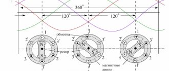
The only primary source of alternating electric current is a generator; a simplified diagram of such a device is shown in the figure.
Simplified illustration of generator design
Designations:
- 1 – direction of rotation;
- 2 – magnet with poles S and N;
- 3 – magnetic field;
- 4 – wire frame;
- 5 – EMF;
- 6 – ring contacts;
- 7 – current collectors.
Pinout of power supply connectors: which line is responsible for what | Computer power supplies | Blog
Connecting the power supply wires when assembling a PC is one of the most difficult tasks that novice users face.
Everyone has heard the phrase “electricity is nothing to joke with,” and you need to understand that if the wires are connected incorrectly, you can easily damage expensive components. To prevent this from happening, you need to know the pinout of the power supply connectors, the maximum load on each connector and the position of the keys that prevent you from connecting the wires incorrectly. In this article you will find all the information on this topic.
Standards for PC power supplies and their connectors have been evolving for almost 40 years, since the release of the first IBM PC . During this time, several AT and ATX standards have changed. It would seem that all possible connectors have already been invented and nothing new is required, but this fall the Nvidia GeForce RTX 3000 series video cards are expected to be released, which will bring with it a new 12-pin power connector. Manufacturers have already begun to add a 12-Pin Micro-Fit 3.0 connector to the cable sets of new power supplies. It wouldn't be surprising if this power connector complements the new ATX standards.
Before moving on to the description and pinout of all connectors in a modern power supply, I would like to remind you that the main voltages that we will encounter are +3. 3 V, +5 V and +12 V. Now the main voltage that is required by both the processor and the video card is +12 V. In turn, +5 V is needed by drives, and +3.3 V is used less and less.
And if you look at the plate that is on the side of each power supply, we will see the voltages, currents and power it produces for each of the channels.
Molex connector
Let's start with the most ancient connector, which has reached our times almost unchanged, having appeared on the first “personal devices”. This is the well-known 4-pin connector called Molex.
Today, the scope of application of this connector has narrowed to powering case fans, front panels of PC cases, splitters and power adapters for video cards and drives. For example, video card power adapters “Molex - PCI-E 6 pin”. Despite the fact that the connector produces up to 11 A per contact, which means it can give the video card, in theory, 132 watts of power, it should be used with extreme caution.
It must be taken into account that the thickness of the wires may not correspond to such power, and the contacts themselves may be loose, with a loose fit.
As a result, this is fraught with heating of wires, contacts and melting of insulation.
If you absolutely need such an adapter, choose a model with two Molex connectors.
Be sure to check the quality of the adapter contacts and insert it securely until it stops. To protect against incorrect connection, the connector has two bevels.
Attention! Despite the fact that the bevels do not allow you to insert the connector on the other side, with a certain force and loose sockets there is a possibility of inserting a connector turned 180 degrees, which will lead to equipment failure.
24-pin motherboard power connector
This connector appeared in the ATX12V 2.0 specifications in 2004 and replaced the legacy 20-pin connector. It can provide quite serious power to power the processor, video card and motherboard: 145.2 W via the +3.3 V line, 275 W via the +5 V line and 264 W via the +12 V line (using Molex Plus HCS contacts).
Note. Molex contacts are certified for 6 A. Molex HCS - up to 9 A. And Molex Plus HCS - up to 11 A.
CPU power connectors
The power consumption of processors has increased steadily over the past 20 years, necessitating the need for additional power connectors for them. And in the ATX12V specifications, an additional 4-pin +12 V processor power connector was introduced.
8-pin processor power connector
Although the 4-pin processor power connector is rated for a maximum power of up to 288 W (using Plus HCS pins), the EPS12V specification version 1.6 introduced in 2000 introduced an 8-pin processor power connector. Initially, this connector was used in servers with serious loads on the power system, but later migrated to ordinary PCs.
Today, even on budget motherboards we find this particular connector, which theoretically can supply up to 576 W of power to the processor.
The 4-pin and 8-pin connectors are compatible with each other. If your PSU only has a 4-pin power cable, it will fit into the 8-pin connector on the motherboard. And an 8-pin cable, accordingly, will fit into a 4-pin connector.
The transmitted power figures look fantastic, but you must understand that this is theoretical power. In practice, manufacturers of top overclocking-oriented motherboards install two 8-pin processor power connectors. For example, on MSI MEG Z490 ACE . Increasing the connector contacts and wire cross-section leads to a decrease in their heating and, as a result, to safe operation.
Attention! When connecting the 8-pin power connectors of the processor and video card, you need to take into account that despite the fact that they do not match in the bevels of the contacts, their plugs are very similar. With a certain amount of force, you can plug the processor power plug into the connector on the video card and vice versa. This will lead to a short circuit and equipment failure.
Power connector for 3.5″ drives
Another connector that is almost never found on new power supplies. Previously used to power 3.5″ drives and some expansion cards.
SATA power connector
Standard connector for powering HDD, DVD and 2.5″ SSD drives. A reliable and convenient connector, which cannot be inserted on the other side due to the location of special protrusions. The current consumed by HDDs and SSDs is quite small and there is no need to worry about heating of such connectors.
Additional power connectors for video cards
At the beginning of the 2000s, the power consumption of video cards increased sharply, which required special power connectors for them, adopted in the ATX12V 2.x specifications.
The PCI Express x16 Graphics 150W-ATX Specification 1.0 was adopted by the PCI-SIG working group in 2004. She introduced a 6-pin connector that can provide 75 W of power to the video card.
And another 75 W are taken from the PCI-E x16 slot. The resulting total of 150 watts is sufficient to power mid-level video cards, for example, GeForce GTX 1650 SUPER .
But these power options quickly became insufficient and soon the PCI Express 2.0 specification was adopted, which already provided an 8-pin power connector for video cards. The 8-pin power connector made it possible to transmit 150 W of power and, together with 75 W coming from the PCI-E x16 slot, the result was 225 W, which was already enough for high-performance video cards.
Video card manufacturers usually try to unload power on the PCI-E x16 slot and provide power reserves for overclocking, so video cards with a consumption of 120 watts and higher, for example, GeForce GTX 1660 SUPER , are increasingly equipped with an eight-pin power connector.
The design of the connectors allows the connection of a 6-pin power cable to an 8-pin connector. But, most likely, you will need a special adapter, because in this case the video card will recognize by the signal contacts which cable is connected to the power connector.
The 8-pin connector is usually made collapsible, which allows it to be connected to a 6-pin socket.
It is impossible to insert connectors of this type incorrectly: the bevels on the pins are located in a strictly defined order. But you need to connect the power all the way - until the safety tab snaps into place.
Im Programm: selbstverständlich Rock-Hymnen wie „TNT”, “Highway to Hell”, “Thunderstruck” or “Hells Bells”. Aber eben kein Klassiker-Gedrängel, all unplanned songs haben ihren festen Platz. Songs aus der Zeit vor 1980, mit den herrlich doppelbödigen Texten, bei denen jeder eingefleischte Fan leise in sein Bon-Scott-Gedenk-Shirt weint.
Musikalisch und optisch sind VOLTAGE dabei so nahe am Original, dass man meinen könnte, die Rock-Ikonen gäben sich höchstpersönlich die Ehre. Instruments and equipment from the 70s instruments for authentication AC / DC-Sound.Ein Schlichter Sound, der heute genauso satt klingt wie damals. Eine Rhythmusfraktion an Bass und Drums, die den rollenden AC / DC-Groove - den unvergleichlichen "Rock'n'Roll Train" - in Bewegung setzt, während der Rhythmusgitarrist die rohen Riffs erbarmungslos aus seiner Gretsch würgt. Ein Angus-Young-Klon in zu enger Schuluniform, mal hingebungsvoll im Blues, dann wieder giftig kreischend, der im Duckwalk wie unter Strom die Bühne kreuzt and beim obligatory striptease tatsächlich sein letztes Hemd gibt.Ein Sänger mit Brian-Johnson-Schiebermütze, der plärrt wie der Alte und presst wie der Neue. Der bei "The Jack" mit rostiger Kehle zum fiesesten Pokerspieler der Welt wird und bei "Rock or Bust" in Johnson-Manier die Wörter auf die Welt zu serveen scheint. Und das Beste: ohne an Authentizität einzubüßen, rockt die Band dermaßen entiastisch durch das Programm, dass sich das Publikum bereitwillig mitreißen lässt.
Diese Mischung aus optischer Ähnlichkeit, Sound-Brett und purer Leidenschaft, die von der Bühne stürmt und einem in die Knochen fährt, macht ein VOLTAGE-Konzert zum echten Live-Erlebnis und zu einem Muss DC für-jeden AC!
Do you want to see us do our thing? All you have to do is connect us to high... VOLTAGE!!
TENSION OF THE TRIP
————————————-
05/06/2017 – 82296 Schöngeising, 25 Jahre Landjugend Schöngeising – Rock im Stadl
05/27/2017 – Schlachthof, Zenettistr. 9, 80337 München, 19:00 Uhr Einlass — 20:00 Uhr Showtime
06/17/2017 - 34. Harley-Davidson Treffen “DAYS OF THUNDER”, am Unterberg in Kössen, Österreich
15.07 ODER 29.07.2017 Esconova Open Air, 86972 Altenstadt
Keine Veranstaltungen mehr.
VOLTAGE ON YOUTUBE
SONG TENSION
BOOKING INFORMATION