Electric meter designation on the diagram
Understanding electrical diagrams and drawings requires a certain level of knowledge. All elements of the electrical network have a conventional graphic designation that helps to clearly identify them. Knowing the meanings of symbols helps to read drawings of any complexity. The problem was the application of old standards, which were last updated a long time ago. Sometimes arbitrary designations of elements are used, but it is recommended to use icons from the standards to avoid double interpretations.
Low meter readings
Usually recording when there is a noticeable difference. It is better to compare the difference according to the readings in the magazine.
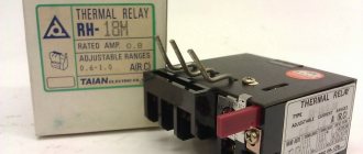
- Check that the current transformer is standard - TKLP-0.66. Another is allowed, but for correct calculation it must be with the parameter 300/5. Disconnect one wire, connect a resistance, for example 10 ohms, and a voltmeter to the current transmitter and check the voltage at the current transmitter at a certain load in the TED armature (see table below).
- Check the meter on the stand.
- If the type of current transformer is with 4 contacts, then connect it to the distantly located contacts. The closest ones are one plate.
| Current transformer parameters | |
| 0.66 kV | nom. voltage |
| 300/5 | 300 A - rated current in the power cable (primary winding) 5 A - rated current in the winding for the meter (secondary winding) This includes the transformation ratio, also indicated on the meter. |
| 10 VA | secondary winding power at rated current |
Normative base
There are a dozen types of electrical circuits, and the number of elements used is in the hundreds. Among this diversity, it is difficult for an untrained person to detect the meter designation, so compliance with uniform rules is important. The regulation of symbols in the electricity supply network is contained in the standards listed below:
- GOST 21.614 Symbolic graphic images of electrical equipment and wiring in the original;
- GOST 2.273-68, GOST 2.279-68, GOST 2-755-87 Conventional graphic designations in diagrams (each of these standards covers its own area, 279 is devoted to current measuring instruments, and 755 to switching equipment);
- GOST 2-702-2011 ESKD. Rules for executing electrical circuits.
The listed standards set out the basic rules for drawing up drawings. There are standards that add details to the information presented; their use is rare, but sometimes you cannot do without them. Studying regulatory documents requires a lot of time, so we will tell you how to find objects of interest in single-line, schematic and other diagrams.
A single-line diagram is a simplified version of a schematic diagram, which leads to the emergence of its own reading features.
Marking of electricity meters
Electrical meters according to the connection diagram, devices and functions are manufactured in various types and are conventionally designated by letters and numbers: C - meter (electricity meter), A - active energy, P - reactive energy, O - single-phase, 3, 4 - for three-wire or four-wire electrical circuits, U - universal, I - induction, the next three digits are the design of the electric meter.
Designation after the numbers: T - in tropical implementation, P - direct-flow (if switching occurs without current transformers), M - modernized. The accuracy class of the meters can be, for example, 2 and 2.5.
In a 220 V power network, where there will be long-term operation in the mode of uneven loads across phases, it is necessary to use three-element or four-wire electricity meters. In private houses and apartments, single-phase meters are used to account for consumed electricity, for example SO-5, SO-I449, SO-I446.
How to choose the right electric meter to buy
Currently, there is a wide variety of electricity meters in stores. According to the characteristics of electricity accounts, meters are divided into: electronic and induction. Today, induction meters are prohibited for installation, as they have a large measurement error. When buying a meter, you need to make sure that it meets the requirements of GOST.
When choosing an electric meter, you need to pay attention to:
- When purchasing a meter, you need to know what type of electric meter you need. This information can be found in the technical conditions of power supply for the apartment in which the meter will be installed. The technical specifications indicate the nomenclature of the electric meter. If these conditions are absent, then only a 1-phase electric meter can be installed. If a three-phase electric meter is needed, it is necessary to make specifications (technical conditions) at the local distribution zone.
- If the electric meter is installed in a room where the ambient temperature is below zero degrees, then study the data sheet for use. An electric meter with an operating temperature of -40 degrees and below is practical. Only electronic meters are suitable for these operating conditions.
- According to the PUE: “newly installed 1-phase meters must have state verification seals with a period of no more than two years. And on 3-phase meters - with a prescription of no more than one year.”
From this we see that the purchased electric meter must already be sealed with two seals (or one on an electronic electric meter). The customer is obliged to check the integrity of the seals. Seals are mounted mainly on screws. They are: external and internal. The seal that is inside looks like red or black mastic poured into a screw groove; there may be silver on top. External ones are made from lead, sometimes from plastic, which are crimped onto a wire thread that is pulled through a hole in a screw or threaded through an eye.
The fillings must have clear embossing and no damage of any kind. Careful attention must be paid to this. The state inspector most often places a copy of the embossing in the form of a stamp on the last page of the passport for the operation of the meter.
On the stamping of the seals the year of verification is indicated, or rather the last 2 digits of the year and information about the state inspector in small symbols between the numbers. On the outside seals, the quarter and year of verification are stamped on the back side, embossed with Roman numeral symbols. When purchasing, you need to look at the verification year, you need to make sure that it is not expired (for a 3-phase meter no more than 12 months, for a 1-phase meter no more than 2 years).
It happens that the meter is sealed with two seals. One has a seal stamped by a state inspector, the other has a seal stamped by the manufacturer’s quality control department and this is considered an acceptable norm. But if two seals have an OTC stamp or an illegible imprint, then you do not need to purchase this meter, because before installation, you must submit the meter to the department of metrological verification and standardization, but this procedure is paid. You will have to perform the same actions if you purchase a meter with an expired verification period.
- It is necessary to focus your attention on the MPI (inter-check interval) of the meter, which is indicated in its operating certificate. It is necessary to clarify how long it will take to send the device for a scheduled check. As a rule, state verification of a 1-phase induction device takes about 16 years, and of an electronic device 8-16 years. The shorter the period of state verification, the higher the quality of the meter. The verification period for a 3-phase meter is much shorter and is 6-8 years. But new 3-phase electronic meters can have an MPI of up to 16 years. The verification period expires based on the year stamped on the device seals.
- It is necessary to find out the accuracy class (CT) of the device, which can be seen on the front of the device. The accuracy class is indicated by a number in a circle. This number indicates the maximum possible inaccuracy of the meter, which is expressed as a percentage of the largest value that a given meter measures from a given range.
Previously, until the end of 1995, 1-phase devices were produced with CT up to 2.5. Since 1996, when the new GOST 6570-96 was approved, electric meters began to be produced with a high CT - 2.0.
Today, devices with KT 2.5 are no longer accepted for scheduled state verification, even though the period of operation of the device has not yet passed (the period of operation of the devices is at least 32 years). Today the state is transferring meters to KT-1.0. From this we can conclude that when purchasing a device with KT 2.0, the device will not be accepted for the next verification, which will be 16 years later.
- It is worth looking at the way the device is secured. The meters are produced with the possibility of being secured with three screws or a din rake. Devices with the method of mounting on a dinrail are made only by electronic meters. When choosing this fastening method, you must purchase a din rake or panel cabinet. But sometimes it is included with the device.
- It is advisable to purchase meters with a protective cap with electrical adhesive, as well as on the bottom of the device, as there have been no complaints from inspectors.
- Make sure that the electrical terminals contain all the necessary bolts, sometimes it happens that they are simply not there.
It is also necessary to check the presence of sealed bolts with a slot for attaching the protective cap.
- Until 1996, single-phase electric meters were produced with an accuracy class of up to 2.5. But after the release of GOST 6570-96, meters began to be produced with a higher accuracy class - 2.0.
- It is not necessary to look at the maximum peak current of a 1-phase device if you do not have a specification, because the modern meter is made very powerful.
From the information presented above, when choosing a meter, you can definitely say which one you need.
Which one should you choose: an induction meter or an electronic one?
The unequivocal answer is that it is electronic, because induction meters are currently prohibited for installation.
A very large assortment of electronic meters has now appeared on our market. All of them have various sets of functions that are mainly of interest only to specialists. The buyer is only interested in CT and tariffication.
CT (accuracy class) of the device
CT is the main general technical parameter of the device. It talks about the level of error of the meter. Until the beginning of 1995, all measuring instruments installed in apartments were with CT 2.5 (hence, the error in meter readings was 2.5%). Since the beginning of 1996, a new standardization of CT 2.0 has been approved. This moment became a turning point in replacing measuring instruments with KT 2.0.
Tariffication
Until the end of the 2000s, all measuring instruments that were installed in apartments had the same tariff. Modern metering devices can calculate electricity by time of day or by season of the year. Devices that have 2 tariffs or more allow you to pay for electricity significantly less (that is, at a certain time there is an automatic switch to the night tariff, which is 2 times lower than the day tariff). Devices with a 2-tariff system are designed for different tariffs: day 7:00 - 23:00, night respectively 23:00 - 7:00. Because the tariff from 23 to 7 is much cheaper, which helps reduce funds. New models of manufactured meters can be reprogrammed to accommodate various tariff changes. That is, for example: the state decided to give discounts on electricity on weekends, but only those meters that have more than 2 tariffs can use these discounts.
Why is a system with 2 tariffs more profitable?
A system with 2 metering tariffs satisfies the needs of the subscriber and the energy system. This is due to the fact that the load at substations is not the same throughout the day: in the mornings and evenings there is a peak in electricity consumption, but at night there is a significant decrease in electricity consumption, which is why it is necessary to reduce the generation of electrical energy. Due to the uneven generation of electrical energy, equipment can be seriously damaged. When peak hours arrive, the company needs to operate at full capacity.
The transition to 2-tariff metering of the population solves the problem of reducing production costs and, therefore, putting into the background the work on introducing additional electrical power capacity, due to the reduction in consumption during peak hours.
Today, all new buildings are equipped with automatic energy calculation systems. These systems help the population to keep a differential count of energy consumed depending on the time of day. These systems consist not only of 2 tariff measuring instruments, but also of additional components that allow you to program meters, as well as receive information from them remotely (at a distance). If your apartment does not have an automated system, then you can use all the advantages of 2-tariff metering by installing a 2-tariff meter with a built-in tariff meter.
What does reliability and MPI (inter-test interval) depend on?
Over time, the materials from which the meter is made age and wear out, so the CT may change. Because of this, the electric meter must be periodically checked for accuracy. The time interval from the first verification (production date) until the next verification is called the inter-verification interval (ICI). MPI is calculated in years, and is also indicated in the operating certificate. Electronic meters have much less MPI than induction meters. The question is why? The answer is simple, because upon careful analysis of the configuration that is used in most meters, it turned out that the parts used for production are not standardized and therefore can often fail or affect the accuracy of the device within the specified period of time.
MPI is closely related to the period of warranty service and operation of the meter. All information is indicated by the manufacturer and when purchasing a meter, you need to focus your attention on all this. It is extremely important that there is a warranty and post-warranty service center in your region.
What is needed to replace an electricity meter?
Anyone can install a new electricity meter at home. Still, if you have already decided to change the meter, you should definitely know that the purchased meter must be listed in the state register. This register consists of a list of domestic and imported electricity meters that have been certified and approved for use in Ukraine.
The next step, supplying it for registration, is carried out after installing the metering device or after its modernization. To register, you need to call an inspector from the electrical supply organization, he will inspect the correct connection of the device. If the device is connected correctly, it will be sealed and will issue permission for its use. After this, the meter will be put into operation and the first readings will be taken from the device. And only after all these operations have been completed, payment will be made according to the readings of the new meter.
Attention! You cannot connect a new electricity meter yourself; dismantling an old electricity meter without the presence of an inspector is a gross violation. A torn or damaged seal carries a different calculation procedure: the calculation will be made according to the power of electrical appliances located in the room.
Reliability of an electric meter depending on price
Previously, the meter had only one requirement: to count the consumed electricity. But today, a metering device helps the owner solve problems with expenses.
To control the error-free charging of electricity bills, you will not need to look for past payment receipts: the meter, according to its function, will demonstrate how much electricity was consumed, for which months and at what tariffs. There is no longer any need to calculate the difference in readings between months; it can do this automatically.
Today there is a very large range of electricity meters. They all have their own characteristics and various functions.
But not everyone needs such features and capabilities; some need an ordinary, accurate and trouble-free meter at a reasonable price. From this varied assortment, you can always choose the meter that satisfies you in terms of price and proper quality.
Finding the counter and other elements on the diagram
When examining the drawing, the specialist understands what is indicated by this or that sign. Uniform marking rules prevent misreading of the drawing, which is important when carrying out various works where contact with electrical energy is possible. Deciphering the diagrams seems difficult only at the beginning of studying the topic; if you have experience, finding an electric meter and other elements of interest will not be difficult. Some symbols are familiar to people from school physics lessons.
When considering the graphic designation of some elements, it is worth paying attention to the details. According to the number of rays in the socket, the number of inputs for plugs. The sockets themselves can be of several types, each of which has its own symbol:
- open-mounted socket;
- hidden socket (recessed into the wall);
- grounded socket;
- waterproof socket (for installation outdoors and in rooms with high humidity);
- three-phase socket.
A meter is present in every diagram; not a single facility that consumes electricity can operate without a meter. The designation of the electric meter on the diagram is not so difficult to find. It is presented in the shape of a rectangle with a vertical stripe separating the top third of the figure, and the Wh symbols are present in the bottom two thirds. Knowing the floor plan helps in locating an electric meter; the meter is installed in places where it is easiest to take readings.
Three phase meters
Three-phase devices for recording consumed electricity are divided into two groups - the old type, which operate from transformers, and electronic ones, which are connected directly. The easiest way to take readings is from an electronic meter. To do this, just press the button and wait for the required readings to appear on the display.
Taking readings from old-style three-phase meters that operate on transformers is not difficult, but you should be careful. Readings are recorded from each phase to which the transformer is connected. The obtained data is multiplied by the transformation coefficient. The result obtained is entered into the receipt as an actual expense. The transformation coefficient is established by GOST or by the controlling company, which, when signing an agreement with the consumer, must indicate this indicator in the document, as well as provide a calculation formula.
The process of taking readings from induction and electric type electricity meters is different. The calculation is carried out according to the same scheme - the reading for the previous month is subtracted from the new value. For three-phase meters, the transformation ratio is also taken into account.
vote
Article rating
The need to read the electrical network diagram
A specialist can quickly find the required element using the icon. Such knowledge is required in various situations, such as repairing an existing electrical network, laying a new one, or installing electrical equipment. To install a new electric meter, you need to find the old one and replace it. On large objects, drawings are confusing, and you need to understand them in a short time. Quickly studying drawings is important in emergency situations.
Knowledge of symbols and skills in reading circuit diagrams or simplified single-line variants may be required for every person. Even a simple replacement of electrical wiring will force you to face difficulties without an understanding of basic things. Reading the drawing helps ensure safety during electrical installation work. Replacing a meter is a common operation, which is why knowing the designation of the meter in the diagram is so important.
Types of single-line electrical diagrams
Depending on at what stage of the work on creating the electrical network of the facility a single-line diagram is drawn up, its type and direct purpose depend. At the stage of developing design documentation, a design single-line diagram is drawn up, which serves as the main document for calculating the parameters of the power supply system. It is this document that is necessary for subsequent approvals with the authorities issuing technical conditions for connecting the construction project to existing electrical networks, which are the electrical grid organizations at the location of the electrical energy consumer facility.
For your information! The procedure for obtaining technical conditions for connecting to electrical networks is regulated by a number of documents. Among them: Decree of the Government of the Russian Federation No. 861 of December 27, 2004 “On approval of the Rules for non-discriminatory access to services for the transmission of electrical energy and the provision of these,” “Rules for non-discriminatory access to the services of the administrator of the wholesale market trading system and the provision of these.” All regulatory documents must be taken into account when developing documentation.
Design diagram of an apartment panel of a country house
At the stage of operation of the facility, single-line executive diagrams are drawn up, which display all the changes made to the configuration of the electrical network during its use. This may be due to the modernization of the equipment used or its replacement, the addition of new capacities or changes in the configuration of trunk and group lines. At large facilities, where the power supply system is divided into several levels, single-line diagrams are drawn up for each group of consumers: “facility as a whole - workshop - section”, etc. Initially, a drawing is made showing the substations (SS) and the configuration of the networks connecting them, then a diagram of the TS or main switchboard (main distribution board) and then - each power or lighting panel available at the facility.
For your information! At facilities of various forms of ownership, the person responsible for the energy sector is responsible for maintaining technical documentation and its compliance with the requirements (PTEEP Chapter 1.2 “Responsibilities, responsibility of consumers for compliance with the rules”).
Executive diagram of a 2-transformer substation
Based on single-line diagrams, other electrical diagrams of the power supply system are developed: structural and functional, fundamental and installation.
Electricity meter designation on the diagram
Understanding electrical diagrams and drawings requires a certain level of knowledge. All elements of the electrical network have a conventional graphic designation that helps to clearly identify them. Knowing the meanings of symbols helps to read drawings of any complexity. The problem was the application of old standards, which were last updated a long time ago. Sometimes arbitrary designations of elements are used, but it is recommended to use icons from the standards to avoid double interpretations.
Normative base
There are a dozen types of electrical circuits, and the number of elements used is in the hundreds. Among this diversity, it is difficult for an untrained person to detect the meter designation, so compliance with uniform rules is important. The regulation of symbols in the electricity supply network is contained in the standards listed below:
- GOST 21.614 Symbolic graphic images of electrical equipment and wiring in the original
- GOST 2.273-68, GOST 2.279-68, GOST 2-755-87 Conventional graphic designations in diagrams (each of these standards covers its own area, 279 is devoted to current measuring instruments, and 755 to switching equipment)
- GOST 2-702-2011 ESKD. Rules for executing electrical circuits.
How to correctly take readings from electricity meters?
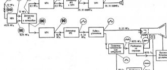
The electrical power of the meter is converted into an analog signal, which once again goes through the conversion process, but this time into a pulse signal. The main element of the electric meter is a microcontroller, which analyzes all signals and calculates the amount of energy consumed.
Also, with the help of this device, information is transmitted to output devices. As for induction meters, they consist of the following elements: an aluminum disk, a voltage coil, a calculation mechanism and a permanent magnet.
Induction
These devices are familiar to many of its users thanks to their glass window, behind which a special disk spins. The speed of its turnover depends on the amount of energy consumed. This type of electric meter is no longer relevant, as it is being forced out of the market by various modern analogues.
Due to its unprofitability, no one installs it now. Induction devices have more disadvantages than advantages, because their design does not allow automation of accounting and, under the influence of certain factors, can distort their readings.
Along with the use, the production of induction meters has also decreased. The reason for this is the preference for newer and more modern types of electricity meters.
Digital
These are newer devices that have become very popular today.
Compared to the previous type, digital electricity meters have many advantages:
- Reliability and accuracy of the system.
- Possibility of simultaneous testing of active and reactive power.
- Possibility of developing multi-tariff installations.
- Implementation of an external interface (change of tariffs, diagnostic and management capabilities).
- Implementation of statistical management.
- Storage of information of accumulated energy for a certain period of time;
With the help of such electricity meters, it is possible to automate energy metering and its distribution. Also, some systems are capable of providing for advance payment of electricity. Moreover, payment information is recorded on an electronic card, which is individual for each user.
Hybrid
These are the rarest species that almost no one uses now. Hybrid meters are not very convenient, since their measuring part is electrical, and their computing part is mechanical.
Procedure for taking readings
From induction meters
The total electricity consumption is calculated from the obtained numbers, which are shown on the meter display. Moreover, you need to take into account all the numbers up to the decimal point, after which the number indicates the amount of a tenth of a kilowatt. Often, the number after the decimal point is indicated in red.
To calculate electricity costs for a month, you need to record readings at the end of each past month, subtracting the readings of the previous month from them. The resulting difference is the amount of electricity consumed per month. This indicator should be measured in kW/hour.
The total amount to be paid is calculated by multiplying the received number of kilowatts by a certain cost of one kilowatt, according to the established tariff.
Thanks to the presence of a rotating disk, some additional indicators can be calculated. One wound up kilowatt of electricity is equal to a certain number of full revolutions of the disk (usually the number of full revolutions is 600-1200).
From digital multi-tariff
For single-tariff ones, first of all, you need to write off all the numbers (up to the decimal point) that are shown on the scoreboard. All these numbers must be included in the payment receipt. The next step is to calculate the amount of electricity used per month. To do this, the indicator for the previous month is subtracted and the resulting number is multiplied by a certain tariff.
The two-tariff type of digital electric meter is represented by a more modern device , which is somewhat different from inductive devices. Also, a two-tariff meter has a slightly different operating principle, which consists of different ways of metering electricity at certain times of the day. For example, electricity metering at night is calculated at a certain tariff, which is much cheaper than during the day.
When taking readings, the first three digits are recorded: the very first shows the amount of electricity used per day, the second digit indicates the electricity consumed per night, and the third shows the total amount of kW electricity consumed. The amount to be paid is calculated by multiplying the total amount of electricity by the established tariff per kilowatt.
To take readings from a three-tariff meter, you must initially press the “enter” button. As a result, the values of all three tariffs will be shown: T1, T2 and T3. All values will be displayed in order, with an interval of 30 seconds. To calculate T1, you need to subtract the current value from the previous reading of the daily tariff. Next, the resulting difference must be multiplied by the established tariff during rush hour. Rush hour is considered to be the morning period from 7 to 10, and the evening period from 17 to 21 hours.
Indicator T2 is a tariff that shows electricity consumption at night. Night hours in all regions are calculated from 11 pm to 7 am. T2 is calculated in the same way as the daily tariff indicator.
As for the third tariff (T3), it is generally considered to be a semi-peak hour, for which two time periods are established: from 10 to 17 hours and from 21 to 23 hours. T3 is calculated by calculating the difference between the current value and the indicator for the previous month.
How to calculate the currently connected power?
Power can be calculated in two ways: by the number of revolutions of the disk and by its rotation speed;
- According to the number of revolutions of the disk. First of all, you need to set the number of disk revolutions for a certain period. On average, the disk rotates about twenty times in five minutes. Therefore, to determine the current power, it is necessary to divide the actual number of revolutions by the average. For example, if in 5 minutes the counter made 30 revolutions, then this indicator must be divided by the average value: 30:20 = 1.5 kW.
- By disk rotation speed. Each meter contains information about how many revolutions it will take to reach 1 kW of electricity. Different types of devices have different speeds. As an example, we can consider an electric meter with a number of 240 revolutions with a consumption of 1 kW. On average, the disk makes 240 revolutions in 1 hour, or more precisely in 3600 seconds.
This means that it makes one revolution in 15 seconds (3600: 240 = 15). If the actual power is greater, then the rotation speed of the disk will also be high.
Let's say that the disk made one revolution in 5 seconds, which means that to calculate the power, you need to divide the average rate by the actual indicator:
Power calculations on digital devices occur in the same way. Only instead of a rotating disk, the main indicator will be a flashing light.
Finding the counter and other elements on the diagram
When examining the drawing, the specialist understands what is indicated by this or that sign. Uniform marking rules prevent misreading of the drawing, which is important when carrying out various works where contact with electrical energy is possible. Deciphering the diagrams seems difficult only at the beginning of studying the topic; if you have experience, finding an electric meter and other elements of interest will not be difficult. Some symbols are familiar to people from school physics lessons.
When considering the graphic designation of some elements, it is worth paying attention to the details. According to the number of rays in the socket, the number of inputs for plugs. The sockets themselves can be of several types, each of which has its own symbol:
- open-mounted socket
- hidden socket (recessed into the wall)
- grounded socket
- waterproof socket (for installation outdoors and in rooms with high humidity)
- three-phase socket.
A meter is present in every diagram; not a single facility that consumes electricity can operate without a meter. The designation of the electric meter on the diagram is not so difficult to find. It is presented in the shape of a rectangle with a vertical stripe separating the top third of the figure, and the Wh symbols are present in the bottom two thirds. Knowing the floor plan helps in locating an electric meter; the meter is installed in places where it is easiest to take readings.
A drawing with a large number of elements can drive an unprepared person into a stupor. Lamps and other lighting devices alone have 14 main designations. If replacement of lighting devices is required, the selection of equipment is carried out in accordance with the requirements of the drawing.
To quickly find the counter and other elements of interest, conventional graphic icons are learned by heart
In single-line and schematic diagrams, several groups that are most widespread can be distinguished:
- sockets
- switches
- lighting
- radioelements
- transformers
- electrical equipment.
Graphic icons are not the only way to represent elements; letter values are widely used. For the electricity meter, Pl is used; if there are several such elements in the network, a number is added (Pl1, Pl2, and so on). Devices are designated in Russian and Latin letters, so the presence of symbols from different alphabets in the drawing should not come as a surprise.
Markings on electricity meters
An electric meter is a rather complex product with a multifaceted internal mechanism of action. As with any other units of this kind, there are markings on the body.
If you know all the designations, you can easily obtain the necessary information about the device without using its passport or attached documentation.
So, let's look at the main elements of marking different types of meters.
Designations on electricity meters
On the outside of the case, in the upper left part, as a rule, there is a number. It means the accuracy class of the device.
Not so long ago, the most common option was considered class “2.5,” which meant a maximum calculation error of 2.5%. However, modern technologies and requirements have left such electricity meters on the margins of history.
Today's realities require devices to have a maximum error of two percent for induction meters and 1% for electronic ones.
Also on the front panel is the letter “C”, which indicates the type of device “Counter”. Next you can see the letters A and P.
They say that the device is capable of taking into account not only active energy, but also reactive energy, which arises as a result of some compensation in induction devices.
By the way, reactive energy can be taken into account separately to control the process of its release and improve the performance of the network.
We know that all meters are divided into single-phase and three-phase. If we are talking about the second option, then on the protective glass you will see the number 3 or 4, which will mean the maximum number of incoming phase wires. There is no such marking on single-phase analogues.
Advice
The mandatory designation is also the type of meter (induction or electronic), which is expressed in the letters I and E.
The need to read the electrical network diagram
A specialist can quickly find the required element using the icon. Such knowledge is required in various situations, such as repairing an existing electrical network, laying a new one, or installing electrical equipment. To install a new electric meter, you need to find the old one and replace it. On large objects, drawings are confusing, and you need to understand them in a short time. Quickly studying drawings is important in emergency situations.
Knowledge of symbols and skills in reading circuit diagrams or simplified single-line variants may be required for every person. Even a simple replacement of electrical wiring will force you to face difficulties without an understanding of basic things. Reading the drawing helps ensure safety during electrical installation work. Replacing a meter is a common operation, which is why knowing the designation of the meter in the diagram is so important.
How to take readings from an electric meter. Instructions for action
The dial of any electricity meter shows how many watts of electricity the subscriber has consumed. Since electricity is paid per kilowatt of energy, let’s find out how to determine it.
How to take electricity meter readings
- Take a sheet of paper and a pen;
- Go to the electric meter and make sure it is in good working order (the numbers are clearly visible, the electric dial does not blink, there is no external damage to the device, the seal is not broken);
- Copy onto paper all the digits of the meter up to the decimal point: for a regular single-tariff meter, one reading is taken;
- for two-tariff – two indicators. The first is responsible for the kilowatt/hours consumed during the day, the second - at night;
- for a three-tariff system – three indicators. The first two are the same as in a two-tariff meter, the third is kilowatt/hours, the consumption of which occurred during the half-peak period.
How many digits does the electricity meter read?
Electric meters based on the number of indicators are:
- three-digit (three digits before the decimal point, one after). The maximum value that the device shows is 1000 kW/hour;
- four-digit (the reading is the same as in the previous one, only there are four digits before the decimal point). The maximum value that the device shows is 10,000 kW/hour.
After reaching the maximum numbers, the counter is reset to zero.
When installing an electric meter in an apartment or private house, a utility representative is required to show the consumer how to take readings from the electric meter. The subscriber may not take electricity readings for the current period. This is done by the controllers of energy organizations. If the electric meter is located outside the consumer’s home, then a specialist takes a reading at any time during the billing period. In the case when the device is located in the subscriber’s home, the time for taking readings by the controller is discussed with the owner.
The technical passport of the electrical appliance indicates the date of its verification. If irregularities in the operation of the meter are detected (twisting, slow movement of the mechanism) at the expense of the consumer, he will bear administrative responsibility.