No instrument in the world is accurate. The value that it measures will always differ from the truth by the amount that is also called its error. This error will determine the accuracy class of the ammeter. The task of all manufacturers of measuring equipment is to ensure that this error is as low as possible and tends to zero.
The error of an ammeter is established as a result of verification and comparison of measurement readings of the same quantities with a reference or reference device that has a higher accuracy class. In this case, the value obtained on the reference device is considered valid.
What is an ammeter and what quantities does it measure?
An ammeter is a measuring device that is used to measure current [I] in electrical circuits. The SI unit of [I] is ampere [A]. Electric circuits can conduct current of different strengths, therefore the instrument scale of the ammeter is calibrated with different gradations from a microampere equal to 1 μA = 1 × 0-6 amperes to a kiloampere equal to: 1 kA = 1,000 amperes.
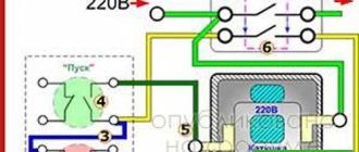
Important! The ammeter is connected in series to the electrical circuit, and to increase the measurement limit, special devices are used: transformers, shunts and magnetic amplifiers.
Since the current in the circuit directly depends on the resistance value [R] of the electrical circuit elements, the device’s own resistance [Ra] must be extremely low, tending to zero. This will reduce the influence of the device in the process of measuring current in the circuit, thereby increasing the accuracy of the measurement.
How to use and connect an ammeter to a circuit?
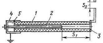
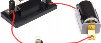
To measure the current in a simple electrical circuit, we must break the circuit anywhere and connect a device to this gap (see Figure 5). This connection is called serial. That is, for example, to measure the current in a conductor, an ammeter is connected in series with this conductor - in this case, the same current flows through the conductor and the ammeter.
Rice. 5. Method of connecting an ammeter in an electrical circuit
In a circuit consisting of a current source and a series of conductors connected so that the end of one conductor is connected to the beginning of another, the current strength in all sections is the same. This follows from the fact that the charge passing through any cross-section of the conductors of the circuit in 1 s is the same. When there is current in an electrical circuit, charge does not accumulate anywhere in the conductors of the circuit, just as water does not accumulate anywhere in individual parts of a pipe when it flows through a pipe. Therefore, when measuring current, the ammeter can be connected to any place in a circuit consisting of a number of series-connected conductors, since the current at all points of the circuit is the same. If you connect one ammeter to the electrical circuit before the lamp, and the other after it, then both of them will show the same current strength.
Attention! You cannot connect an ammeter to the source terminals without some kind of current receiver connected in series with the ammeter. You can ruin the ammeter!
For each ammeter there is an upper limit of measurement (maximum current), that is, the ammeter scale shows what maximum current it is designed for. Including an ammeter in an electrical circuit with a higher current strength is unacceptable, as it may fail.
When turning on the device, it is necessary to observe the polarity, i.e., the terminal of the device must be connected only to the wire coming from the terminal with the “+” sign of the current source. When the device is turned on correctly, the electric current through the ammeter should flow from the “+” terminal to the “-” terminal.
When connected to a circuit, the ammeter, like any measuring device, should not affect the measured value. Therefore, it is designed in such a way that when it is connected to a circuit, the current strength in it almost does not change. As we already know, any electrical measuring instruments have a certain electrical resistance. When an ammeter is connected in series to an electrical circuit, its electrical resistance is added to the total electrical resistance of the electrical circuit. This causes an undesirable reduction in current. To prevent this from happening, the resistance of the ammeter must be low. The ideal would be an ammeter without resistance (R = 0), but in practice this is impossible to achieve.
Types of ammeters
They can be electromechanical or analogue, digital or electronic. The basic set usually consists of a detector, a transmitter and an indicator, a recorder or a storage device.
Analog devices are the oldest instruments in use. Although they are reliable for static and stable measurements, they are not suitable for dynamic and transient conditions. In addition, they are quite bulky and have limitations due to the use of a dial indicator.
Electronic instruments respond faster and are able to instantly detect dynamic changes in current in the network. An example is a digital multimeter, which is capable of measuring dynamic or transient current values in seconds.
Types of ammeter errors
To understand the size of the measurement error, you need to compare the results obtained with the reference ones.
In metrology, several types of errors are used for all electrical meters, both ammeters and voltmeters: absolute, relative and reduced.
The absolute error of an ammeter is the difference Δ between the measurement result obtained on the instrument scale (Xi) and the actual value of the current in the circuit (Xd). The absolute error of an ammeter is described by a simple formula and is expressed in units of current A.
Δx = Xd−Xi, A
Where:
- Δx - delta X
- Xd is the actual reading of the current strength received by the reference device;
- Xi is the measured value on the instrument scale.
Relative error (δ) is the ratio of the absolute error of the ammeter Δx to the actual current reading taken from a standard device. It can be indicated as a percentage, then the quotient is multiplied by 100, or expressed in relative units.
δ = (Δx : Xd)×100, %
The reduced error is the value reduced to the measurement range of the ammeter, which is equal to its scale. It is obtained as a quotient of the absolute error Δх and the normalized value (Xн), in values corresponding to the absolute error Δх multiplied by 100%:
δpr = (Δх : Xн)×100, %
CONVENTIONAL GRAPHIC SYMBOLS ON THE DEVICE SCALE.
The scale of the device is used to read the measured value. In addition, the scale provides detailed technical characteristics of the device using symbols, which is necessary to know for the correct selection and use of the device.
On the scale of the device its name or symbol is written. On electrical diagrams, the device is designated by a circle or rectangle, in which the corresponding letter value is written.
The instrument scale indicates the type of current being measured (direct, alternating), the system of the measuring mechanism, and the accuracy class (numbers indicating the accuracy class are sometimes circled).
Each device is designed for certain operating conditions, which is also indicated on the scale. The degree of protection from external magnetic fields is indicated by Roman numerals I, II, III, IV.
The operating conditions of the device at the appropriate temperature and humidity are indicated on the scale by letters:
A - works normally at temperatures from +10 to +35°C and relative humidity up to 80%.
B - operates normally at temperatures from -20 to +50°C and relative humidity up to 80%.
B - operates normally at temperatures from -40 to +60°C and relative humidity up to 98%.
During operation, the device must be positioned as indicated on its scale.
The scale of the device indicates the voltage value at which the electrical strength of its insulation was tested, as well as the manufacturer's brand, serial number, year of manufacture and type of device.
| 1,5 __ ~ | Accuracy class Direct current Alternating (single-phase) current The device is installed vertically; horizontally; at an angle. The insulation of the device is tested at a voltage of 2 kV |
METHODS OF MEASUREMENT OF ELECTRICAL QUANTITIES.
Current measurement.
The current strength is measured using an ammeter, which is connected in series to the circuit. An ammeter has an electrical resistance that is significantly less than the resistance of the circuit in which it is connected. Therefore, the ammeter does not noticeably change the current in the circuit.
With the same ammeter of the magnetoelectric system, if a shunt
You can measure current within different limits. A shunt is a manganin conductor with little resistance. Shunts can be built inside the ammeter housing.
Such devices have a measurement limit switch. If the shunt is attached to the device, then it. connected to the ammeter terminals in parallel
Ammeters:
a - portable; b.—panel; c—scheme of connection to the circuit
Shunts to ammeters Diagram for connecting a shunt to an ammeter
In this case, you need to determine the scale division price based on the current value for which the shunt is designed
Voltage measurement.
The voltage is measured using a voltmeter, which is connected in parallel to the circuit.
A voltmeter has an electrical resistance that is significantly greater than the resistance of the circuit (section of the circuit) in which it is connected, and therefore it does not noticeably change the voltage in the circuit.
To expand the measurement limits of this voltmeter, additional resistors are used.
The additional resistor is a high-resistance magnanin conductor wound in the form of a coil. An additional resistor can be placed inside the device body. These voltmeters have a measurement limit switch. If an additional resistor is attached separately to the device, then it is connected to the voltmeter in series. In this case, it is necessary to determine the value of the scale division based on the voltage value for which the additional resistor is designed.
Voltmeter:
A -
panel;
b -
connection circuit for measuring the voltage of the current source;
c
- connection diagram for measuring voltage on a section of the circuit
Additional resistors for voltmeters
Diagram for connecting an additional resistor to a voltmeter
Power measurement.
Electric current power is measured using a wattmeter.
The connection diagrams for wattmeters are shown in the figure.
According to the diagram (Fig. a), one of the terminals of the current winding must be connected to one of the terminals of the voltage winding. These terminals are connected in the device to the terminals marked with an asterisk (Fig., b). Therefore, before connecting the wattmeter to the circuit, first connect the terminals marked with an asterisk using a short insulated wire.
Power in direct current circuits, as well as in alternating current circuits, if they do not contain capacitors and electrical receivers, can also be measured using an ammeter and voltmeter. Power is determined from instrument readings. P=I*U
Schemes for connecting wattmeters:
a - schematic diagram; b - circuit diagram for connecting wattmeters of various types when measuring the power of an electrical receiver R
Measurement of current work.
Current work (energy consumption) is measured using an electricity meter.
Accuracy class
This is the main characteristic of an ammeter, which, according to the still in force Soviet GOST 1845-59, determines the limits of possible errors.
For all electrical measuring instruments to which it belongs, the accuracy class (Cl) is indicated in numerical form by the value corresponding to the maximum permissible reduced error δpr, in%.
All electrical ammeters are divided according to accuracy into 8 classes, and then into groups, which is an important feature of their classification:
- Exemplary: 0.05–0.1–0.2;
- laboratory: 0.5–0.1;
- technical: 1.5–2.0–4.0.
Note! All devices with an error exceeding 4% are extracurricular.
Exemplary ones are used in electrical measuring processes to determine the accuracy class of technical and laboratory ammeters. Laboratory ones are used in scientific and technical processes during electrical engineering studies of control of operating modes, for example, in boiler houses, hydroelectric power plants, thermal power plants and nuclear power plants.
Important! On the ammeter panel, the accuracy class is indicated in circles, squares and asterisks. If it has an uneven measurement scale, Kl is indicated by a broken line.
Symbols of electrical measuring instruments
Block diagram and conversion equation
Electromechanical measuring mechanisms
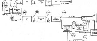
In the general case, electromechanical devices consist of a measuring circuit, a measuring mechanism, a reading device and are built according to the direct conversion block diagram shown in Fig. 4.4.
Rice. 4.4
The measuring circuit converts the measured quantity X into an electrical quantity X1, which directly affects the measuring mechanism.
The measuring mechanism (MM) consists of fixed and moving parts. In MI, electromagnetic energy is converted into mechanical energy of movement of the moving part. Under the influence of the measured value, a torque MVR is created in the measuring mechanism, which rotates the moving part of the MI. In the general case, the torque depends on the measured value X and the angle of rotation of the moving part a: MVR = f(X, a). For electromechanical devices, the torque is found as
MVR = dWe /da, (4.3)
where We is the electromagnetic field energy concentrated in the measuring mechanism.
In order for each value of the measured quantity to correspond to a certain value of the deflection angle a of the moving part, in the measuring mechanism, when the moving part is rotated, a counteracting moment MPR is created, directed towards the rotating one and depending on the angle of rotation. When mechanically creating a counteracting moment, MPR = Wa, where W is the specific counteracting moment. From the condition of steady equilibrium
MVR = MPR = dWe /da = Wa, (4.4)
we obtain that the angle of rotation of the moving part depends on the measured quantity, the parameters of the device and can be found as
a = F(X, A) = / W, (4.5)
where A are the parameters of the measuring mechanism.
Equation (4.5) is called the transformation equation of the measuring mechanism of an electromechanical device.
The counteracting moment in measuring mechanisms can be created not only mechanically (springs, stretch marks), but also by the measured quantity itself. Mechanisms in which a counteracting moment is created by a measured quantity are called ratiometers.
The reading device is used for visual reading of the values of the measured quantity and consists of a scale and a pointer.
According to their shape, scales are divided into: rectilinear, arc and circular
(arc angle greater than 1800); according to the ratio of the lengths of divisions within one scale, they are divided into: uniform and uneven, when the ratio of the length of the largest division to the smallest (scale unevenness coefficient) exceeds 1.3; by the number of scales: single-scale and multi-scale [6].
Scales and all inscriptions characterizing the device are applied to the base (dial) and are standardized by GOST 5365-83.
The following symbols are applied on the scales of electromechanical devices:
a) designation of the type of current (for example, "__" - direct current; "~ " - alternating current; " ~ -" - direct and alternating current;
b) designation of the unit of the measured quantity (for example, mA, B);
c) designation of the operating position of the device:
— for the horizontal position of the scale;
- use the device in a vertical position of the scale;
Ð a0 — for setting at an angle a0;
d) designation of the accuracy class (for example, 1.5; 2.5; 1.5);
e) designation of the test voltage of the insulation of the measuring circuit in relation to the housing, for example, 2 - test voltage, for example, 2 kV.
In addition, the scale shows a symbolic image of the principle of operation and the letter designation of the device. Table 4.1 shows the symbols of some types of devices.
Table 4.1
Pointer and light indicators are used to determine instrument readings based on scale marks..
When an electromechanical device operates in a dynamic mode, in addition to rotating and counteracting moments, moments arise due to inertia, environmental resistance, and eddy currents. When the moving part moves in the device, a dynamic moment arises that seeks to calm this movement and is called a calming moment. This moment determines the settling time of the device. To obtain the required settling time, a special structural element is made in the measuring mechanism - a damper. In electromechanical devices, air, liquid and magnetic induction dampers are used.
Depending on the principle of operation of the measuring mechanism, electromechanical devices are divided into the following groups: magnetoelectric, electromagnetic, electrodynamic, ferrodynamic, electrostatic, induction.
Block diagram and conversion equation
Electromechanical measuring mechanisms
In the general case, electromechanical devices consist of a measuring circuit, a measuring mechanism, a reading device and are built according to the direct conversion block diagram shown in Fig. 4.4.
Rice. 4.4
The measuring circuit converts the measured quantity X into an electrical quantity X1, which directly affects the measuring mechanism.
The measuring mechanism (MM) consists of fixed and moving parts. In MI, electromagnetic energy is converted into mechanical energy of movement of the moving part. Under the influence of the measured value, a torque MVR is created in the measuring mechanism, which rotates the moving part of the MI. In the general case, the torque depends on the measured value X and the angle of rotation of the moving part a: MVR = f(X, a). For electromechanical devices, the torque is found as
MVR = dWe /da, (4.3)
where We is the electromagnetic field energy concentrated in the measuring mechanism.
In order for each value of the measured quantity to correspond to a certain value of the deflection angle a of the moving part, in the measuring mechanism, when the moving part is rotated, a counteracting moment MPR is created, directed towards the rotating one and depending on the angle of rotation. When mechanically creating a counteracting moment, MPR = Wa, where W is the specific counteracting moment. From the condition of steady equilibrium
MVR = MPR = dWe /da = Wa, (4.4)
we obtain that the angle of rotation of the moving part depends on the measured quantity, the parameters of the device and can be found as
a = F(X, A) = / W, (4.5)
where A are the parameters of the measuring mechanism.
Equation (4.5) is called the transformation equation of the measuring mechanism of an electromechanical device.
The counteracting moment in measuring mechanisms can be created not only mechanically (springs, stretch marks), but also by the measured quantity itself. Mechanisms in which a counteracting moment is created by a measured quantity are called ratiometers.
The reading device is used for visual reading of the values of the measured quantity and consists of a scale and a pointer.
According to their shape, scales are divided into: rectilinear, arc and circular
(arc angle greater than 1800); according to the ratio of the lengths of divisions within one scale, they are divided into: uniform and uneven, when the ratio of the length of the largest division to the smallest (scale unevenness coefficient) exceeds 1.3; by the number of scales: single-scale and multi-scale [6].
Scales and all inscriptions characterizing the device are applied to the base (dial) and are standardized by GOST 5365-83.
The following symbols are applied on the scales of electromechanical devices:
a) designation of the type of current (for example, "__" - direct current; "~ " - alternating current; " ~ -" - direct and alternating current;
b) designation of the unit of the measured quantity (for example, mA, B);
c) designation of the operating position of the device:
— for the horizontal position of the scale;
- use the device in a vertical position of the scale;
Ð a0 — for setting at an angle a0;
d) designation of the accuracy class (for example, 1.5; 2.5; 1.5);
e) designation of the test voltage of the insulation of the measuring circuit in relation to the housing, for example, 2 - test voltage, for example, 2 kV.
In addition, the scale shows a symbolic image of the principle of operation and the letter designation of the device. Table 4.1 shows the symbols of some types of devices.
Table 4.1
Pointer and light indicators are used to determine instrument readings based on scale marks..
When an electromechanical device operates in a dynamic mode, in addition to rotating and counteracting moments, moments arise due to inertia, environmental resistance, and eddy currents. When the moving part moves in the device, a dynamic moment arises that seeks to calm this movement and is called a calming moment. This moment determines the settling time of the device. To obtain the required settling time, a special structural element is made in the measuring mechanism - a damper. In electromechanical devices, air, liquid and magnetic induction dampers are used.
Depending on the principle of operation of the measuring mechanism, electromechanical devices are divided into the following groups: magnetoelectric, electromagnetic, electrodynamic, ferrodynamic, electrostatic, induction.
How to determine the accuracy class
According to current state standards, ammeter manufacturers are required to guarantee its relative measurement error, obtained according to the accuracy class indicated on the measuring panel and in the device passport. In addition, all measuring instruments must undergo periodic verification at metrological centers to ensure compliance with the factory accuracy class. If it does not pass such certification, it cannot be used in measurement processes.
Knowing the absolute error and the current reading on the scale, you can simply obtain the real current acting in the circuit. In this case, the scale for applying the absolute error is considered uniform.
Important! When choosing a dial ammeter scale, it is necessary that the operating current value is approximately 2/3 of the scale range. If the needle is almost at 0 or at the maximum scale reading, then the relative error will be very high, that is, it is not recommended to trust such readings.
3. Symbols of devices on connection diagrams (external wiring).
The symbols of instrumentation and automation devices on connection diagrams (external wiring) do not differ from the symbols on circuit diagrams. Therefore, in this section we should consider the cable markings on external wiring. Description of the implementation of external wiring diagrams are carried out in accordance with GOST 2.702-2011 “RULES FOR EXECUTION OF ELECTRICAL DIAGRAMS”, part 5.4 “Rules for execution of connection diagrams”.
I will not cite various excerpts from this GOST. I just recommend viewing it for general understanding. According to clause 5.4.19 “On the diagram, using an alphanumeric designation, it is possible to determine the functional affiliation of a wire, harness or cable (stranded wire, electrical cord) to a specific complex, room or functional circuit. There are no other requirements for cable designation. And again in this case we will turn to generally accepted rules applied in international standards.
Single cables from instrumentation devices to junction boxes (local panels) must have the same identification number as the instrumentation device.
To distinguish a cable from a harness, the letter C - Cable - Cable.
To designate several cables suitable for one device, put the letters A, B, C .
P at the end of the tag number (postfix) .
Cable designation examples:
- C-1111-1-FT-3001-A - Installation 1111, Section 1, control cable between the FT-3001 flow meter and the junction box - the first cable.
- C-1111-1-FT-3001-B - Installation 1111, Section 1, control cable between the FT-3001 flow meter and the junction box - second cable
- C-1111-1-FT-3001-P - Installation 1111, Section 1, FT-3001 Flowmeter External Power Supply Cable and Junction Box
Trunk cables are designated, as well as the equipment to which the cable is connected - junction boxes, local panels. is also preceded by the letter C. If there are several cables connected to the equipment, the letter A, B, C .
C-1111-1-JB-001 -Unit 1111, Section 1, cable between junction box JB-001 and building-installed instrumentation equipment.
4. Symbols of devices on layout diagrams (route plans)
The alphanumeric designation of devices, on the layout diagrams of instrumentation and automation equipment (route plans) in the information presented above is sufficient. All that remains is to consider the designation of the cable trays. There are no requirements for marking cable trays either in GOST 2.702-2011 “RULES FOR EXECUTION OF ELECTRICAL DIAGRAMS” or in GOST 21.210-2014 “CONVENTIONAL GRAPHIC REPRESENTATIONS OF ELECTRICAL EQUIPMENT AND WIRINGS ON PLANS.” When developing a small project, such as a pumping station, compressor station, tank farm, etc. You can limit yourself to the numbering of cable trays - No. 1, 2, 3... This designation will be very difficult to apply when developing a project for a large installation, with long main cable trays and a large number of branches from the main trays in different sections of the routes.
Let's consider what designation of cable trays is used in international projects.
- IS - Intrinsically safe - Intrinsically safe signals - cable trays for intrinsically safe circuits. IS cable trays accommodate ESD, DCS, PLC and MMC cables.
- NIS - Not intrinsically safe - Non-intrinsically safe circuits - cable trays for non-intrinsically safe circuits. NIS Cable Trays are used to lay ESD and DCS cables, solenoid valve control cables, gas control systems, and 24V DC power cables.
- FF - Foundation Fieldbus - digital two-way data transmission system - cable trays for the FF digital communication system of the controller with bale devices.
- P - Public address / general alarm - Two-way communication system / general alarm - cable trays for two-way communication systems up to 110 V. Cable trays P contain cables for two-way intercom, public address system loudspeakers, as well as fire alarm and fire extinguishing system cables.
- PA - Public address/ general alarm - Two-way communication system / general alarm - cable trays for two-way communication systems above 110 V. Cables for two-way intercom, light and sound detector cables are laid in PA cable trays.
- IE - Instrument Electrical Interface - power supply for instrumentation devices - cable trays for power supply of instrumentation and communication equipment with voltage of ~220 V.
- S - System kommunikation - Communication system - cable trays for data transmission systems, including FOCL (fiber-optic communication line).
The complete designation of a cable tray consists of a letter designation and a digital designation. The digital designation consists of 3 digits. In the digital designation, the first digit indicates the floor of the cable gallery.
- 0-The lowest floor of the cable gallery
- 1-Second floor cable gallery
- 2-Third floor cable gallery
For example:
IS-001 – cable tray for intrinsically safe circuits, located on the lower floor of the cable gallery.
NIS-101-1 - cable tray for non-intrinsically safe circuits, located on the second floor of the cable gallery - a branch from cable tray No. 1.
5. Symbol of instrumentation and automation equipment on drawings of automation equipment installations
“CONVENTIONAL GRAPHIC REPRESENTATIONS OF ELECTRICAL EQUIPMENT AND WIRINGS ON PLANS” are carried out in accordance with GOST 21.210-2014. This GOST contains graphic images of the equipment. There are no letter designations for equipment that was not indicated on the functional and electrical diagrams.
There is a need to symbolize equipment not indicated in the above diagrams. Let's consider some options according to international standards. To understand the decoding of instrumentation and automation equipment, first consider the abbreviation of some designations of the automation system.
- PLC : Process Logic Controller - programmable logic controller - PLC
- DCS - Distributed Control System - distributed control system - DCS.
- ESD - Emergency shut-down - Emergency shutdown - emergency protection system -PAZ
- PIMS - Process Infrormation Management System - Process Information Management System
- ECS - Electrical Control System - Electrical Control System
- UPS - Uninterruptable Power Supply - Uninterruptible Power Supply - UPS
- OWS - Operator Workstation - operator's workplace
- EWS - Engineering Workstation - automated workplace of an engineer.
When designating equipment and control cabinets, symbols are used for identification, depending on their affiliation with the system. Below are examples:
- ESD- Emergency shut-down Cabinet – ESD system control cabinet
- ESM-ESD Marshaling Cabinet – cross cabinet of the PAZ system
- DCS- Distributed Control System Cabinet - Distributed control system cabinet (DCS)
- DCM- Distributed Control System Marshaling Cabinet – Cross cabinet of a distributed control system (DCS)
- CFA - Cabinet Fire Alarm System
- CFS - Cabinet Fire Extinguishing
- SRC - Server Cabinet
- FOC - Fiber Optic Patch Panels Cabinet
- IEI - Instrument Electrical Interface - Electrical connection cabinet for instrumentation (intermediate relays)
- IMC - Interconnecting Marshaling Cabinet
- MC - Maintenance Console/ Maintenance Console
- OC - Operating Console
- SC - Supervision Console/ Management Console.
The full symbol of the equipment consists of the installation number, the symbol of the equipment and the serial number of the equipment. For example 1111-DCM-01.
According to GOST 2.710-81 clause 1.1. Conventional alphanumeric designations (hereinafter referred to as designations) are intended:
- — for unambiguous recording in an abbreviated form of information about elements, devices and functional groups (hereinafter referred to as parts of the object) in the documentation for the object;
- — for links to the corresponding parts of an object in text documents;
- - for application directly to the object, if this is provided for in its design.
6. Tables of symbols ISO-14617-6-1 and GOST 21.208-2013
For further analysis of symbols in automation schemes of international projects, I propose the opportunity to consider the table of symbols ISO-14617-6-1. Translation of the table in the near future.
ISO-14617-6-1 symbol tables in Russian
Symbol tables GOST 21.208-2013
An example of finding an ammeter reading from the given error
For example, we consider an analog meter with a scale of up to 25 A.
The scale has a designation of accuracy class 2.5, there is no circle or square, so this error is given.
Y=Dх/Xп×100=+/- p
At Xp = 25A and p value = 2.5, the absolute error can be calculated:
Δх =25/100×2.5=0.625 A
If the user finds an accuracy class enclosed in a square on the panel, then the error will need to be determined as a percentage of the measured value.
With scale readings Ii = 10 A, the instrument error should not exceed
Δх =10×2.5/100=0.25
When reading on a scale Ii = 2 A, the error will be different:
Δх =2×2.5/100=0.05
When reading on a scale Ii = 25 A, the error will be maximum:
Δх =25×2.5/100=0.625
This is why it is important that an analog instrument operates at 2/3 of the operating scale.
An example of finding an ammeter reading by relative error
In order to find out the error for an ammeter with an accuracy class of 0.05/0.02, the measurement scale is 0...25 A. Δx is determined by the measured reading on a 10A scale.
Since the accuracy class is specified as c/d, the calculation will be performed according to the formula:
δ pr =+/-(с+d(xk/(x-1)))
Where:
- xk=25 A;
- x=10 A;
- c=0.05;
- d=0.02.
δ pr =100 Δx / xN
Standard value xN=xk=25 A,
δ pr =+/-(0.05+0.02(25/(10-1)))=0.105
Δх = δ pr×xN/100=0.105×25/100=0.026 A
Selecting an ammeter based on metrological characteristics
The most common source of error when measuring current is that the ammeter has a non-zero input resistance. The voltage generated across the meter causes the voltage across the device under test to decrease. If the reduction is significant, it will result in significantly less current flowing. In other words, the meter does not show the current that is actually flowing in the network.
In order to minimize this error as much as possible, two main types of measurement architecture are used: shunt ammeters and feedback ones.
The error caused by a shunt meter, expressed as the ammeter's partial voltage divided by the output resistance.
Ammeters with feedback are closer to “ideal”. It produces voltage in the feedback path of the high gain op amp. This voltage is also proportional to the measured current, but does not appear at the input of the device. As a result, sensitive closed-loop meters such as electrometers and picoammeters have a voltage load typically limited to 200 µV.
For industrial measurements, analog panel-type ammeters are most often used. When choosing them, you should consider the following points:
- Type selection. When measuring I DC, you should choose a DC meter, that is, with a magnetoelectric measuring mechanism. When measuring AC current, you need to pay attention to the waveform and frequency. If it is a sinusoid, then only the effective value is measured, followed by conversion to the maximum or average value.
- Accuracy class. The higher the accuracy class of the meter, the higher its price, the more difficult its repair and metrological certification. Therefore, to perform most engineering measurements, an accuracy class of 1.5 is sufficient; you should not use standard or laboratory instruments.
- Selecting a scale. To make full use of the ammeter's accuracy class capabilities, the measured value must be in the range of 1/2 ~ 2/3 of the maximum scale.
Important! Internal resistance is a determining value when choosing a meter. It should be taken according to the magnitude of the measured impedance, otherwise it will lead to large measurement errors. Since internal resistance reflects the power consumption of the meter itself, when measuring current, a device with internal resistance should be selected as low as possible.
GOST 2.729-68 ESKD. Conditional graphic designations in schemes. Electrical measuring instruments
STATE STANDARD OF THE USSR UNION
UNIFIED SYSTEM OF DESIGN DOCUMENTATION
CONDITIONAL GRAPHIC DESIGNATIONS IN SCHEMES
GOST 2.729-68
Moscow
STATE STANDARD OF THE USSR UNION
| Unified system of design documentation CONDITIONAL GRAPHIC DESIGNATIONS IN SCHEMES.
| GOST 2.729-68 |
Date of introduction 1971-01-01
This standard establishes symbolic graphic symbols of electrical measuring instruments on diagrams, performed manually or automatically, for products from all sectors of industry and construction.
(Introduced additionally, Amendment No. 1, 3).
Designations of electrical measuring instruments are given in the table.
| Name | Designation |
| 1a. Sensor of measured non-electrical quantity | |
| 1. Electrical measuring device | |
| a) showing | |
| b) registering | |
| c) integrating (for example, an electric energy meter) | |
| Notes: 1. If it is necessary to display non-standardized electrical measuring instruments, you should use combinations of the corresponding basic designations, for example, a combined indicating and recording device. 2. To indicate the purpose of an electrical measuring device, the conventional graphic symbols established in the ESKD standards are included in its designation. as well as letter designations of units of measurement or measured quantities, which are placed inside the graphic designation of an electrical measuring device | |
| a) ammeter | |
| b) voltmeter | |
| c) double voltmeter | |
| d) differential voltmeter | |
| d) voltammeter | |
| e) wattmeter | W |
| g) summing wattmeter | ∑ W |
| h) varmeter (active power meter) | var |
| i) microammeter | μ A |
| j) milliammeter | tA |
| l) millivoltmeter | mV |
| m) ohmmeter | Ω |
| n) megohmmeter | M Ω |
| o) frequency meter | Hz |
| n) wave meter | λ |
| p) phase meter: measuring phase shift | φ |
| power factor measuring | cos φ |
| c) ampere-hour meter | Ah |
| t) watt-hour meter | Wh |
| y) reactive volt-amp-hour meter | varh |
| f) thermometer, pyrometer | t ° ( Θо allowed |
| x) polarity indicator | + — |
| i) tachometer | n |
| h) pressure meter | Pa or P |
| r) liquid level meter | |
| w) signal level meter | dB |
| 3. It is allowed to enter the necessary data in the designations of electrical measuring instruments in accordance with the current standards for electrical measuring instruments. 4. If it is necessary to indicate the characteristics of the reading device of the device, then the following qualifying symbols are entered into its designation: a) a device, the moving part of which can deviate in one direction from the zero mark: | |
| right | |
| left | |
| b) a device whose moving part can deviate in both directions from the zero mark | |
| it is allowed to use the designation | |
| c) vibration system device | |
| d) a device with a digital readout | |
| e) device with continuous recording (recording) | |
| e) a device with point registration (recording) | |
| g) printing device with digital registration | |
| h) device with perforated registration | |
| For example: | |
| voltmeter with digital reading | |
| continuous recording voltmeter | |
| ammeter, the moving part of which deviates in both directions from the zero mark | |
| 2. Galvanometer | |
| 3. Synchronoscope | |
| 4. Oscilloscope | |
| 5. Oscilloscope | |
| 6. Oscillographic galvanometer: a) current or voltage | |
| b) instantaneous power | |
| 7. Pulse counter | |
| 8. Electrometer | |
| 9. Semiconductor bolometer | |
| 10. Temperature sensor | |
| 10a. Pressure meter | |
| Note: If it is necessary to indicate a specific quantity into which a non-electrical quantity is converted, the following designations can be used, for example, pressure sensor | |
| 11. Thermoelectric converter: a) with non-contact heating b) with contact heating | According to GOST 2.768-90 According to GOST 2.768-90 |
| Clause 12 according to GOST 2.728-74 | |
| 13. Secondary clock | |
| Note. To indicate hours, minutes and seconds, use the following notation | |
| 14. Primary hours | |
| 15. Clock with contact device | |
| 16. Synchronous clock, for example, at 50 Hz | |
| 17. Maximum active power indicator with feedback from the wattmeter | |
| 18. Differential voltmeter | |
| 19. Solenometer | |
| 20. Recording combined wattmeter and varmeter | |
| 21. Time counter | |
| 22. Watt-hour meter that measures energy transmitted in one direction | |
| 23. Watt-hour meter with registration of maximum active power | |
| 24. Distinctive symbol of the function of counting the number of events | |
| 25. Electrical impulse counter with manual setting to n (set to zero at | |
| 26. Electrical pulse counter with electrical zeroing | |
| 27. Electrical impulse counter with several contacts; contacts are closed respectively at each unit (10°), ten (101), hundred (102), thousand (103) events recorded by the counting device | |
| 28. A counting device controlled by a cam and controlling the closure of the contact every P events | |
| Notes to paragraphs 1-28 1. When depicting the windings of measuring instruments in a spaced manner, the following symbols are used: | |
| a) current winding | |
| b) voltage winding | |
| c) sectioning winding with taps: | |
| current | |
| voltage | |
| d) sectional winding switchable: current | |
| voltage | |
| 2. The winding in the diagrams of measuring instruments, reflecting their relative position in the measuring mechanism, is depicted as follows: | |
| a) current winding | |
| b) voltage winding | |
| c) current windings for addition or subtraction | |
| d) voltage windings for addition or subtraction | |
| For example, a measuring mechanism: | |
| single-winding ammeter | |
| single-winding voltmeter | |
| single-phase wattmeter | |
| three-phase single-element wattmeter with two current windings | |
| three-phase two-element wattmeter | |
| three-phase three-element wattmeter | |
| magnetoelectric logometer (for example, ohmmeter-logometer) | |
| ferrodynamic logometer (for example, frequency meter) | |
| electrodynamic logometer (for example, single-phase phase meter) | |
| three-winding logometer (for example, a three-phase phase meter with two current windings) | |
| four-winding logometer (for example, three-phase synchronoscope) | |
| four-winding logometer (for example, a three-phase phase meter with one current winding) | |
| 3. The output contacts of the windings may not be depicted if this does not lead to misunderstanding | |
| 4. The output contacts of the windings may not be blackened, for example, a single-winding voltmeter | |
(Changed edition, Rev., No. 1, 2, 3).
INFORMATION DATA
1 DEVELOPED AND INTRODUCED by the Committee of Standards, Measures and Measuring Instruments under the Council of Ministers of the USSR
2 APPROVED AND ENTERED INTO EFFECT by Resolution of the Committee of Standards, Measures and Measuring Instruments under the Council of Ministers of the USSR dated August 1, 1968 No. 1208
3 INSTEAD GOST 7624-62 regarding section. 6
4 REFERENCE REGULATIVE AND TECHNICAL DOCUMENTS
| Designation of the referenced technical document | Item number |
| GOST 2.721-74 | 12 |
5 REISSUE (January 1995) with Amendments No. 1, 2, 3, approved in October 1981, October 1990, October 1993 (IUS 11-81, 1-91, 5-94)