Electrical circuits
An electrical circuit is a collection of devices through which electric current flows.
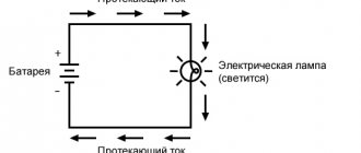
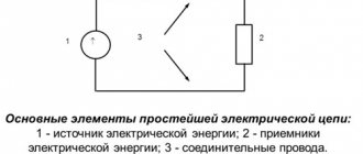
Let's consider the simplest electrical circuit. What does it consist of? It has a generator - a current source, a receiver (for example, a light bulb or an electric motor), and a transmission system (wires). For a circuit to become a circuit, and not a set of wires and batteries, its elements must be connected to each other by conductors. Current can only flow through a closed circuit. Let's give one more definition:
An electrical circuit is a current source, transmission lines and a receiver connected to each other.
Of course, source, receiver and wires are the simplest option for a basic electrical circuit. In reality, different circuits include many more elements and auxiliary equipment: resistors, capacitors, switches, ammeters, voltmeters, switches, contact connections, transformers, etc.
Electrical circuit
By the way, read about what a transformer is in a separate article on our blog.
By what fundamental characteristic can all electric current circuits be divided? Same as current! direct circuits , and there are alternating current circuits . In a direct current circuit, it does not change its direction; the polarity of the source is constant. Alternating current changes periodically over time, both in direction and in magnitude.
Nowadays alternating current is used everywhere. Read about what Nikola Tesla did for this in our article.
What is the current in the outlet - direct or alternating?
People who are more or less familiar with electrical engineering can easily answer the question of what current is in the outlet. Of course it's variable. This type of electricity is much easier to produce and transmit over long distances, and therefore the choice in favor of alternating current is obvious.
There are two types of current - direct and alternating. To understand the difference and determine whether the outlet has direct or alternating current, you should delve into some technical features. Alternating current has the property of changing in direction and magnitude. Direct current has stable qualities and direction of movement of charged particles.
Alternating current comes out of the power plant generators with a voltage of 220-440 thousand volts. When approaching an apartment building, the current is reduced to 12 thousand volts, and at the transformer station it is converted to 380 volts.
Advice
The voltage between phases is called linear. The low-voltage section of the step-down substation produces three phases and a zero (neutral) wire. Energy consumers are connected from one of the phases and the neutral wire.
Thus, single-phase alternating current with a voltage of 220 volts enters the building.
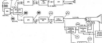
The distribution diagram of electricity between houses is presented below:
In the home, electricity is supplied to the meter, and then through automatic machines to the boxes of each room. The boxes contain wiring throughout the room for a couple of circuits - electrical outlets and lighting equipment.
The machines can be provided one for each room or one for each circuit.
Taking into account how many amperes the outlet is designed for, it can be included in a group or connected to a dedicated circuit breaker.
Alternating current accounts for approximately 90% of all electricity consumed. Such a high specific gravity is due to the peculiarities of this type of current - it can be transported over considerable distances by changing the voltage at substations to the required parameters.
Sources of direct current are most often batteries, galvanic cells, solar panels, thermocouples.
Direct current is widely used in local networks of automobile and air transport, in computer electrical circuits, automatic systems, radio and television equipment.
Direct current is used in contact networks of railway transport, as well as on ship installations.
The diagram below shows the fundamental differences between direct and alternating currents.
Home electrical network parameters
The main parameters of electricity are its voltage and frequency. The standard voltage for home electrical networks is 220 volts. The generally accepted frequency is 50 hertz. However, in the USA a different frequency value is used - 60 hertz. The frequency parameter is set by the generating equipment and is unchanged.
It will be interesting➡ What is a contactor, its features and connection diagrams
The voltage in the network of a particular house or apartment may be different from the nominal value (220 volts). This indicator is influenced by the technical condition of the equipment, network loads, and substation load. As a result, the voltage may deviate from the specified parameter in one direction or another by 20–25 volts.
Current load
All sockets have a certain marking, by which you can judge the permissible current load. For example, the designation "5A" indicates a maximum current of 5 amperes. Acceptable indicators must be observed, since otherwise the equipment may fail, including fire.
The markings on the sockets are shown in the figure below:
All legally sold electrical appliances are accompanied by a passport indicating the power consumption or current load rating.
The largest consumers of electricity are household appliances such as air conditioners, microwave ovens, washing machines, electric stoves and ovens.
For normal operation, such devices will need an outlet with a load of at least 16 amperes.
note
If the documentation for electrical household appliances does not contain information about the consumed amperes (current strength in the outlet), the required values are determined using the electric power formula:
The power indicator is in the passport, the network voltage is known. To determine electricity consumption, you need to divide the power indicator (indicated only in watts) by the voltage value.
Elements of electrical circuits
All elements of electrical circuits can be divided into active and passive. The active elements of the circuit are those elements that induce EMF. These include current sources, batteries, and electric motors. Passive elements – connecting wires and electrical receivers.
Receivers and current sources, from the point of view of circuit topology, are two-pole elements (double-terminal). To operate, they require two poles through which they transmit or receive electrical energy. Devices through which current flows from a source to a receiver are four-terminal. To transfer energy from one two-terminal network to another, they need at least 4 contacts, respectively for receiving and transmitting.
Resistors are elements of an electrical circuit that have resistance. In general, all elements of real circuits, down to the smallest connecting wire, have resistance. However, in most cases this can be neglected and the elements of the electrical circuit can be considered ideal when calculating.
There are symbols for depicting circuit elements in diagrams.
By the way, read more about current strength, voltage, resistance and Ohm’s law for elements of an electrical circuit in a separate article.
Current-voltage characteristic is a fundamental characteristic of circuit elements. This is the dependence of the voltage at the terminals of the element on the current that passes through it. If the current-voltage characteristic is a straight line, then the element is said to be linear. A circuit consisting of linear elements is a linear electrical circuit. A nonlinear electrical circuit is a circuit in which the resistance of sections depends on the values and direction of the currents.
What are the ways to connect elements of an electrical circuit? No matter how complex the circuit is, the elements in it are connected either in series or in parallel.
When solving problems and analyzing circuits, the following concepts are used:
- A branch is a section of a circuit along which the same current flows;
- Knot – connection of chain branches;
- A circuit is a sequence of branches that forms a closed path. In this case, one of the nodes is both the beginning and the end of the path, and the other nodes appear in the circuit only once.
To understand which is which, let's look at the picture:
By the way! For our readers there is now a 10% discount on any type of work
AC voltage
As we know from physics lessons, current is the movement of charged particles that occurs under the influence of an electromagnetic field, potential difference and tension. The main characteristic of any voltage is its dependence on time. Based on this, a distinction is made between constant and variable quantities. The value of a constant practically does not change over time, but the value of a variable changes.
It will be interesting➡ Work and current power
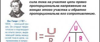
Ohm's law
In turn, a variable characteristic can be periodic or non-periodic. Periodic is a voltage whose values are repeated at regular intervals. The non-periodic is capable of changing at any period of time.
Scheme for describing the physical meaning
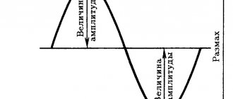
Voltage in an alternating circuit is a parameter that changes its value over time. To simplify explanations, sinusoidal harmonic alternating voltage will be considered in the following.
The minimum time during which a variable repeats is called a period. Absolutely any periodic quantity can be written as a dependence on any function. If time is t, then the dependence will be denoted by F(t). Thus, any period in time has the form: F(t+-T) = F(t), where T is the period.
The physical quantity that is the reciprocal of the period is called frequency. It is equal to 1/T. Its unit of measurement is the hertz, while the unit of measurement of the period is the second.
f = 1/T, 1 Hz = 1/s = s to the minus first power.
Oscillation formulas
Important! The most common functional dependence of a variable network is in the form of a sinusoid. That is why it was taken as the basis for this material.
It is known from mathematics that a sinusoid is the simplest periodic function, and with its help, any other periodic functions can be represented from several sinusoids with multiple frequencies.
Sinusoidal voltage in absolutely any period of time can be described by the instantaneous characteristic: u = U * sin(ωt + φ), where ω = 2πf = 2π/T, where U is the maximum voltage (amplitude), ω is the angular rate of change, φ is the initial phase, which is determined by the displacement of the function relative to the zero coordinate point.
Sine function
Part (ωt + φ) is a phase that characterizes the voltage value in a specific period of time. From this it turns out that amplitude, angular velocity and phase are the main characteristics of variable networks that determine their values in any time interval.
Important! When considering a sine function, the phase is often taken to be zero. In practice, they also often resort to some other parameters, including effective and average voltage, shape factor.
AC voltage regulator
Classification of electrical circuits
According to their purpose, electrical circuits are:
- Power electrical circuits;
- Electrical control circuits;
- Electrical measurement circuits;
Power circuits are designed to transmit and distribute electrical energy. It is the power circuits that conduct current to the consumer.
Circuits are also divided according to the current strength in them. For example, if the current in the circuit exceeds 5 amperes, then the circuit is power. When you click a kettle plugged into a socket, you close a power electrical circuit.
Electrical control circuits are not power and are designed to activate or change the operating parameters of electrical devices and equipment. An example of a control circuit is monitoring, control and signaling equipment.
Electrical measurement circuits are designed to record changes in the operating parameters of electrical equipment.
Voltage formula
There is a formula in physics, although it has no practical application. The official formula is written like this.
voltage formula
Where
A is the work done by the electric field to move a charge along a section of the circuit, Joules
q - charge, Coulomb
U—voltage on a section of the electrical circuit, Volts
In practice, the voltage across a section of a circuit is derived through Ohm's law.
It will be interesting➡ Features of using pass-through switches
voltage from Ohm's law
Where
I - current, Amperes
R - resistance, Ohms
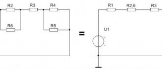
Calculation of electrical circuits
To calculate a circuit means to find all the currents in it. There are different methods for calculating electrical circuits: Kirchhoff's laws, the loop current method, the nodal potential method and others. Let's consider the application of the loop current method using the example of a specific circuit.
First, we select the contours and designate the current in them. The direction of the current can be chosen arbitrarily. In our case - clockwise. Then for each circuit we will compose equations according to Kirchhoff’s 2nd law. The equations are composed as follows: The circuit current is multiplied by the circuit resistance, and the products of the current of other circuits and the total resistance of these circuits are added to the resulting expression. For our scheme:
The resulting system is solved by substituting the initial data of the problem. We find the currents in the branches of the original circuit as the algebraic sum of the loop currents
Whatever circuit you need to calculate, our specialists will always help you cope with the tasks. We will find all currents using Kirchhoff's rule and solve any example of transient processes in electrical circuits. Enjoy your studies with us!