Switches are a broad class of switching devices capable of connecting, disconnecting and serving as conductors in electrical circuits under conditions of operating and emergency currents.
It is the ability to switch increased currents that arise when the operating conditions of electrical networks deviate from the normal mode that distinguishes switches from other switching devices, including:
- disconnectors designed for switching only no-load currents;
- load switches capable of breaking the rated operating current of an electrical installation.
Purpose
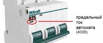
Thus, the technical properties possessed by circuit breakers (short designation VA) allow them to be used for the following purposes:
- switching electrical circuits;
- protection of electrical installations by automatically switching them off when an emergency current value occurs.
VAs are used in electrical networks and electrical installations of all voltage levels, however, the generally accepted term “circuit breakers” implies low-voltage devices operating in conditions up to 1000 volts.
Frequently encountered manufacturers: ABB, IEK, Schneider-Electric, Legrand.
Those machines that operate in higher voltage networks are not called “automatic” which, of course, is not entirely logical. The level of automation of high voltage equipment is usually higher than that of low voltage equipment. But the main thing is not to get confused in the terminology in order to understand what we are talking about.
Dimensions using ABB as an example (mm) depending on the number of poles. Dimensions may differ from other manufacturers, for example, heights are 80, 88, 90, 104 mm.
Design and principle of operation
One of the main components of the machine is its power contacts. The VA is usually turned on manually - by pressing the power button or raising the control handle up. In this case, the spring mechanism is charged, and the elements of the contact group are pressed against each other with a certain force. Maintaining the cocked state of the spring mechanism is ensured by a locking latch that holds the mechanical drive in the on position.
Sectional view, typical approximate view.
Switching off can be done either manually or automatically when the circuit breaker protection device is triggered. In the simplest case, the protective functions are performed by two components - electromagnetic and thermal releases.
Electromagnetic release
The ER is a current coil (solenoid) with a movable electromagnetic core - the striker. The current of the powered electrical installation constantly passes through the coil. The solenoid operates at a certain value of the current flowing through the contacts of the machine. Usually this is a current value several times, or even orders of magnitude, greater than the rated value. When a short circuit occurs in the protected circuit, under the influence of emergency values, the solenoid rod extends and presses on the latch of the mechanical drive of the release. As a result of its release, the switch drive breaks the contact under the action of the spring force.
Thermal release
The thermal release usually consists of a bimetallic strip through which current flows. In fact, the current can flow not through the plate itself, but through a high-resistance conductor wound on it, heated by the current and transferring heat to the plate. A bimetallic strip is
thin strips of two metal alloys welded together. Materials are selected in such a way that their coefficient of thermal expansion has a large difference. This is necessary so that when the bimetal is heated, the plate bends - after all, one of its layers expands much more actively.
Further, when a certain critical bend is reached, the plate acts on the latch lock, turning off the switch. StabExpert.ru reminds that the system parameters are selected in such a way that heating of the plate begins when a current flows through it exceeding the nominal value by about 20%. In this case, the higher the current value, the more active the heating occurs, therefore, the faster the critical bend is reached and the machine is switched off.
Release difference
Summarizing the description of the operation of these two mechanisms, it can be noted that the electromagnetic type release is a current protection without time delay, which is called current cutoff
. The current cutoff reacts to overcurrents that occur during short circuits in the protected network.
The thermal release makes it possible to realize the integral dependence of the protection response time on the current value. Thermal protection ensures equipment shutdown when it is overloaded, when the consumed current is 20% or more greater than the rated current. Under these conditions, the cutoff does not yet operate, but long-term operation of the equipment in this mode is unacceptable.
Protection of the machine under different overloads
The thermal release mechanism will not operate at small and short-lived currents above the rated current. If the current duration is greater than the rated one, the thermal release will operate. The time it takes to turn off the machine by thermal protection can reach up to an hour.
Circuit breaker mechanisms
The time delay allows you not to turn off the circuit breakers in case of significant starting currents of the engine and short-term surges of current. The time-current characteristic of thermal releases also depends on the ambient temperature. At elevated temperatures, thermal protection will work faster than in the cold.
An overload can be caused by turning on several household appliances - a kettle, washing machine, air conditioner, electric stove. When overloaded, the machine turns off, but it is impossible to turn it on immediately; you need to wait for the bimetallic plate to cool down.
Difference from other switching devices
The question may arise as to what is the difference between a circuit breaker and other switching devices that are not capable of switching significant currents. The fact is that switching current loads, namely their disconnection, is accompanied by the occurrence of an electric arc. Moreover, the greater the current value, the stronger the arc discharge when the contacts are disconnected. Arc combustion occurs in ionized air space, that is, the air becomes electrically conductive. Depending on the interrupted current and network voltage, the arc discharge in a gap of a certain magnitude may not go out at all after the contacts are disconnected.
An example is electric arc welding, where by setting the required gap between the electrode and the workpiece, the arc can be maintained continuously. In addition, the electric arc burning at the contact break ionizes the surrounding space and causes a phase-to-phase short circuit in the case of multi-pole switching devices.
But this only applies to disconnectors. The circuit breaker is equipped with special arc-extinguishing chambers, the typical design of which contains a number of parallel plates; they divide the arc into separate sections, where it is extinguished. There is also a path for the removal of gases generated during arc combustion. Each pole of the machine is equipped with a personal arc-extinguishing chamber, which prevents the spread of electromagnetic shock to the contacts of adjacent phases.
VA types (pole and four groups)
The types of circuit breakers can be classified according to several criteria; we will dwell on some of them.
Number of poles: 1p, 2p, 3p and 4p
This characteristic shows how many independent electrical circuits the machine can switch. According to this parameter, VAs are divided into single-pole (designation 1p), two-pole (2p), three-pole (3p) and four-pole (4p).
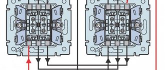
Each pole is a separate mechanical contact that has two terminals for connecting external electrical circuits. Sometimes the poles are called main circuits, i.e. These are circuits of contacts designed to switch currents of the protected load.
The number of poles (1p, 2p, 3p, 4p) of each switch can be easily determined.
The concept of main poles or circuits was introduced because Some types of machines have up to several auxiliary contacts. These contacts are not intended for switching power electrical loads and are not equipped with arc extinguishing devices. There are also auxiliary contacts (also called block contacts), they work in signaling and blocking circuits.
Time-current characteristic
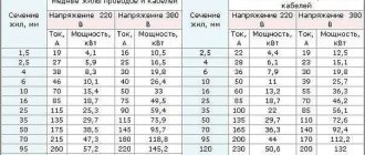
Depending on the characteristics of the electrical circuit, the circuit breaker must have appropriate protection properties. The value of short circuit currents is a characteristic of the supply network, and not of the connected load. A load of the same rated power and voltage can be connected to powerful substation busbars, or to a long power line, at a great distance from the power source. StabExpert.ru reminds that in the first case, the short circuit current will have a maximum value, in the second, due to the influence of the resistance of the power line, it can be significantly reduced. Thus, when choosing a suitable circuit breaker, it is not enough to take into account only the load characteristics; you need to have calculated values of short circuit currents at the intended installation location.
Division into groups A, B, C, D
To operate in various networks, circuit breakers are produced with different time-current characteristics. On this basis, in accordance with GOST R 50345-99
, all machines are divided into four groups - “A”, “B”, “C” and “D”. The devices of each of these groups have their own requirements in terms of protective characteristics. Let's take a closer look at them.
There is one requirement for circuit breakers with a type “A” characteristic: when currents flow that exceed the rated value by 5 times, it must be switched off in a time of less than 0.1 s.
For example, a switch is designed for a rated current of 25 amperes, that is, Inom = 25A. At a current of 5*Inom = 125A, the response time of the release should be less than 0.1 s.
As for machines with characteristics “B”, “C” and “D”, there are both common requirements for all three groups and individual requirements. They normalize the shutdown time at various levels of exceeding the rated current:
- at a current of 1.13 Inom, that is, exceeding the rated value by 13%, circuit breakers with a rating of up to 63 amperes must operate before shutting down for at least one hour, switches for a current over 63 amperes, respectively, for at least two hours;
- a current of 1.45 In should lead to the shutdown of circuit breakers with a rating of up to 63 amperes in less than one hour, and circuit breakers over 63 amperes in less than two hours;
- when the rated current is exceeded by 155% (2.55 In), circuit breakers up to 32 amperes are turned off within a time from 1 to 60 seconds, circuit breakers over 32 amperes - from 1 to 120 s.
The shutdown characteristics of each group are as follows:
- type “B” turns off in more than 0.1 second at three times the rated current and in less than 0.1 second. at tenfold;
- disconnection of type “C” switches – more than 0.1 sec. at 5*Inom, less than 0.1 sec. at 50 In;
- the “D” type automatic machine should not operate earlier than 0.1 sec. with a tenfold increase in rated current.
What is the effect of temperature on the machine?
To answer this question, let's look at the standard characteristics of the machine (for example, Acti9 iC60N) at different temperatures. The control temperature for household machines is 30 degrees Celsius. — the right graph in Fig. 1 corresponds to it.
Fig. 1 Characteristics of a modular machine at different temperatures (from the Acti 9 catalog, Schneider Electric)
Note the guaranteed non-trip (Int=1.13*In) and trip (It=1.45*In) thermal trip currents in the upper left of this graph. For a control time of 1 hour (3600 s), with a multiplicity of 1.13, the machine will definitely not work, but with a multiplicity of 1.45, it will definitely work and disconnect the connection. I think you are familiar with these quantities.
Now let's look at the left graph in Fig. 1. Here the same curves are plotted for a temperature of 50 degrees C. As you can see, the guaranteed currents have become smaller (1.05 and 1.3) and seem to have shifted to the left.
The same deviations, only to the right, occur as the temperature decreases. Conventionally, this can be shown in Fig. 2.
Fig. 1 Characteristics of a modular machine at different temperatures (from the catalog “System pro M compact”, ABB)
Thus, when the temperature increases, there is a risk of false disconnection of the machine from operating currents, or even its thermal damage, and when it decreases, there is a risk of failure of the cable overload protection if it is selected according to the control temperature.
Time delay switches
Automatic circuit breakers equipped with a mechanism for setting the operation time, regardless of the current value, are called selective. Accordingly, devices that do not have this quality are classified as non-selective. Let's look at what selectivity is and why it is needed.
Selectivity is
one of the main qualities that protection must have. Selectivity lies in the necessary and sufficient amount of protective shutdowns of the damaged section of the network. This means that in the event of equipment damage (for example, a short circuit), the protection must operate so that only the damaged circuit segment is disconnected. All other equipment should remain in operation whenever possible. Let us show with an example what the switch time delay has to do with this.
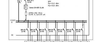
Let’s assume that switch “1” is installed at the power input of the 0.4 kV section. Several outgoing lines are fed from this section through line switches. Let switch “2” be installed on one of the outgoing lines.
Now suppose that there is a short circuit at the very beginning of this line. Which switch should be turned off by the protections in order to isolate only the damaged area? Of course, "2". But the short circuit current in this situation flows through two switches - “1” and “2” (the short circuit is fed from the source through the input switch “1”). How can we ensure that only switch “2” is turned off, since the value of the current flowing through these switches is almost the same? This is where the ability to set an artificial shutdown time delay on the input machine “1” comes to the rescue. In this case, the protection simply does not have time to operate, since the linear switch “2” will turn off the short circuit current without a time delay.
Checking the functionality of the release
Testing of releases of all three types is carried out using the influence of a primary current from an independent source, both when installing the machine and regularly throughout its entire service life. Switches are tested at the same time as other protective equipment.
The main parameter during testing is the compliance of the declared parameters of the mechanism with its technical indicators at the time of testing. The first thing that is checked when assessing performance is the time elapsed from the start of supplying the critical load to the machine until the circuit is released. The parameters of the normal time range are indicated by the manufacturer in the technical documents attached to the device. In case of non-compliance with the standards, the switches are replaced with new ones.
Such checks are necessary to ensure stable and safe operation of the device, and neglecting them can be fatal.